Avoiding Flow-Induced Sympathetic Vibration in Control Valves
Compressible fluid flow through control valves will inevitably cause some form of flow-induced vibration in the fluid system. Identifying the type and cause of the vibration requires detective work. Determining the design changes required in the valve and fluid system to prevent the vibration from occurring requires advanced analytical techniques.
There are very good reasons for power plant designers to specify reciprocating control valves oriented in the flow-to-open direction (flow tending to lift the plug) where compressible fluids are involved. One good reason is that this configuration allows the use of noise-abatement trims, such as drilled-hole cages and tortuous path stacks. Another application advantage is to protect a compressor from surges by allowing the flow to lift the plug and open the valve in the event of stem or actuator failure (Figure 1).
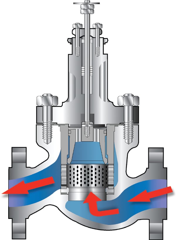 |
| 1. Flow-to-open cutaway. Control valves equipped with noise-abatement trim, such as a drilled-hole cage or a tortuous path stack, are typically oriented in the flow-to-open direction. This orientation maximizes noise attenuation by allowing the expanding gases to exit the valve trim and continue downstream without re-converging through the valve’s seat ring, as would happen if the flow direction were reversed. Source: GE Energy |
There can, however, be unintended, and unwelcome, consequences. Under certain conditions, low-pressure cells will detach from the valve body wall, creating eddies that are carried downstream with the flow until they dissipate. These eddies produce periodic pressure pulsations that can damage the valve trim and body, leading to unplanned and costly downtime for repairs.
Although there are many forms of vibration present in a typical power plant, this article focuses on the cause of flow-induced sympathetic vibration (see sidebar). In addition, it discusses the interaction of the fluid with the valve trim, using computational fluid dynamics (CFD) to analyze the fluid flow in the valve under real-world conditions. Strategies to help prevent vibration and resulting performance problems are also offered.
Flow-Induced Vortex Formation
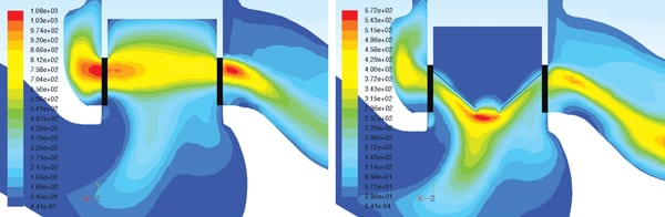
In applications incorporating an in-line globe valve oriented in the flow-to-open direction, the process fluid has to negotiate the turn as it approaches the valve trim. This produces a low-pressure region adjacent to the seat ring (Figure 2). The severity of the decrease in pressure depends on the valve geometry, fluid velocity, and fluid properties.
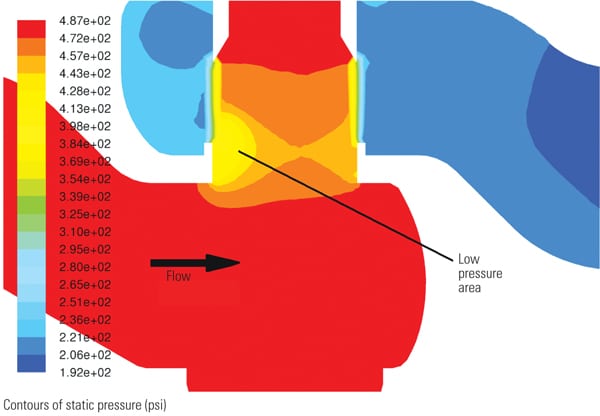 |
| 2. Undersized valve. A CFD pressure plot illustrates flow through an undersized valve oriented in the flow-to-open direction. Note the large low-pressure zone adjacent to the valve seat ring. Under certain conditions, this low-pressure region will detach from the valve body wall, enter the free stream, and form a free eddy. Source: GE Energy |
Under certain conditions—when the pressure becomes low enough and the velocity is high enough—the low-pressure region will detach from the valve body wall, enter the free stream, and form a free eddy. These eddies are continuously created, even under steady state flow conditions, and are similar to the von Kármán street vortices shed behind a bluff body in a free stream.
The CFD pressure plots shown in Figure 2 and Figure 3 illustrate how these low-pressure areas can be formed. Each shows natural gas flowing through a valve. Both valves have the same mass flow and a pressure drop ratio of approximately 2:1. The valve in Figure 2, however, is undersized, while the valve in Figure 3 is adequately sized. In the undersized valve, flow velocity increases in the valve inlet, creating a large low-pressure area where detached vortices could form.
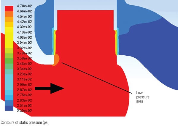 |
| 3. Adequately sized valve. A CFD pressure plot showing flow through an adequately sized valve oriented in the flow-to-open direction. Note the absence of low-pressure zones. Source: GE Energy |
Identifying a potential source of eddies is only half the battle, though; it says nothing about the possibility of detachment or the subsequent movement of the vortices. Fluent CFD, using the detached eddy simulation (DES) model illustrated in Figure 4, can complete the analysis and help predict transient eddy detachment.
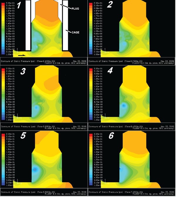 |
| 4. DES eddy. This series of images, captured during a detached eddy simulation (DES), shows a low-pressure eddy forming and detaching from the valve body wall. Source: GE Energy |
DES uses a transient (nonsteady) analysis in combination with viscous turbulence to predict the time-varying nature of the flow. This analysis requires selecting very small time steps in order for the CFD software to capture changes in the fluid flow over time and show the eddies forming and detaching. In this example, the images showing contours of constant pressure were taken at discrete time intervals roughly 0.4 milliseconds apart and show the low-pressure eddies forming and then breaking away.
It is also important to note the pressure pulsations that form inside the hollow cavity of the valve plug. Many cage-guided valves, such as compressor anti-surge valves and main steam valves, have hollow plugs to reduce weight and balance the pressure across the plug. The pressure pulsations create a similar periodic forcing function inside the hollow cavity of the valve plug.
Another unintended consequence of the low-pressure zone, shown in Figure 2, is that it effectively narrows the seat ring orifice, increasing the pressure drop across the seat and reducing the pressure drop across the valve cage, thereby diminishing controllability and reducing flow capacity. While acceptable results may be achieved through proper valve sizing and noise calculation, these unforeseen phenomena must be understood to avoid problems after installation.
In sum, the above analysis shows that vortex shedding is generated by high-velocity flows navigating sharp bends in valves, that vortex shedding is periodic in nature, and that the vortices interact with the valve trim. The next question that must be answered is: Can vortex shedding cause severe valve vibration?
Natural Frequency Resonance of the Plug-Stem System
Figure 5 shows an idealized view of a soft mass-spring system—a control valve plug at the end of a relatively slender valve stem. The lateral modes of this assembly are not allowed to develop, as the valve cage effectively restricts the side-to-side motion of the plug before any amplitude can build up. The torsional first natural mode, however, is unconstrained, as the plug rotates freely around about the stem axis like a tetherball oscillating around the pole.
The top of the stem is held steady by the actuator and is defined as the node of the system, where the amplitude is zero. The bottom of the system, at the plug, is defined as the anti-node, where the amplitude is greatest.
Real-world valves include damping in the form of valve stem packing friction, contact between the plug and the cage, and contact between the stem and a guide bushing. Natural frequency in a simple rod-mass system is inversely proportional to the polar moment of inertia (plug mass at a certain radius) and directly proportional to the square of the stem diameter.
Stem and plug systems in large control valves generally have lower torsional mode frequencies than do smaller valves and are, therefore, more likely to be excited by the valve flow. During excitation, very small displacements will build up if insufficient damping is present, and once the amplitude builds, it is very difficult to stop the motion.
It is important to note that although the forces imparted by the pressure pulses are very small, it is the sympathetic periodic beating over a period of time that creates the destructive vibration amplitude. Frictional damping, such as that produced by the control valve stem packing, can prevent the buildup of amplitude but is not very effective because the packing is close to the node of the system (the top of the stem), where the amplitude is at a minimum, and farthest away from the plug, where motion is greatest.
As discussed earlier, the plug-stem system can also be excited by other sources occurring upstream of the valve, such as vibration and pressure pulsations generated by compressors and pumps.
The primary abatement strategies to a natural frequency response are source modification and reducing structure sensitivity. Source modification involves reducing the cause of the vibration, such as fluid excitation. Reducing structure sensitivity involves changing the design of the valve trim in order to make it less sensitive to the fluid excitation.
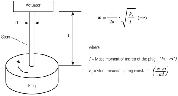 |
| 5. Mass spring system. A simplified torsional mass-spring system. Source: GE Energy |
Source Modification
As shown in Figures 2 and 3, lowering the inlet velocity and reducing the swirl through the valve body will lessen the severity of the low-pressure zones as the flow negotiates the turn into the seat ring. This lowers the turbulent energy in the stream, which in turn lessens the magnitude of the pressure pulsations produced by the detached eddies. At a certain inlet velocity, vortex production can even be eliminated. A properly sized control valve can accomplish this.
Reducing the swirl in the upstream piping will reduce the overall turbulent energy in the flow stream and is considered good design practice. ANSI B31.1 2007 Appendix II recommends that eight to 10 pipe diameters of straight pipe run upstream of a safety relief valve in order to prevent vibration caused by fluid-structure interaction. Concentric reducers with included angles of less than 15 degrees are also recommended to reduce the turbulence of the flow entering the valve.
Finally, protective plug caps can lessen the effect of pressure pulsations within a hollow plug (Figure 4) by preventing pressure pulsations from entering the plug cavity. These caps also have the added benefit of transferring the point of maximum turbulent energy from the plug-cage interface, where it could cause the most harm, to the tip of the plug cap (Figure 6).
 |
| 6. Plug cap reduces turbulence. This pair of images shows the effect of a plug cap on redistributing turbulent energy. In the valve on the right, a protective cap on the plug helps prevent pressure pulsations from entering the plug cavity and transfers the point of maximum turbulent energy from the plug-cage interface, where it could cause the most harm, to the tip of the plug cap, where the potential risk is less. Source: GE Energy |
Reducing Structure Sensitivity
Raising the natural frequency of the plug-stem system will make it less sensitive to flow-induced excitation by increasing the amount of energy required to produce vibration amplitude. There are two ways to change the natural frequency of the system: reduce mass moment of inertia and increase stiffness.
Reducing the inertia of the plug can be readily accomplished by decreasing the plug wall thickness, but considerations of plug strength and manufacturability limit the usefulness of this approach.
Increasing the stiffness of the torsional system can be achieved by increasing the stem diameter. However, though this can significantly increase natural frequency, it is usually quite difficult to implement in real-world applications because further changes may be required to bonnets, packing, and possibly pressure vessel bolting.
Finally, the system can be desensitized with damping. As with any free vibration system, the amplitude of the excitation does not need to be very large to be problematic; it only needs to be constant and occur close to the natural frequency of the system. The much-viewed footage of the Tacoma Narrows Bridge, where gentle pulsations led to the bridge’s destruction, is a prime example of this phenomenon. (The video can be viewed at http://tinyurl.com/24fg4l.) When the motion is just beginning, the amplitudes are very small and even a very small amount of system damping in the form of nonreversible energy drain can stop the motion. This can take the form of mechanical friction between parts or viscous damping.
Providing closer clearances between the plug and cage, or even a seal ring near the bottom of the plug, can provide the required damping. For example, in a recent compressor anti-surge valve application, the valve was fitted with a plug cap and lower plug piston ring. The stem diameter also was selected based on a strain energy evaluation. Together, these tactics reduced the valve vibration energy by more than 50%.
It is important to note that the velocity or kinetic energy of the process fluid in the cage or stack has no impact on flow-induced sympathetic vibration. In the flow-to-open direction, the pressure pulsations caused by detached eddies and turbulence from upstream equipment and piping all occur before the process fluid enters the valve cage or stack. For a specified mass flow rate, selecting a cage or multi-stage stack that further lowers acoustic noise or trim kinetic energy will have no effect on valve vibration.
The abatement strategies outlined here are meant to serve as guidelines and a starting point for use in control system design and valve specification. Every valve application is, of course, unique and should be reviewed by an experienced valve application engineer to determine the likelihood of sympathetic flow vibration and identify the appropriate remedies.
— Asher Glaun ([email protected]) is a senior principal engineer in the Valve Development department at GE Energy. This article is based on a presentation given at KCI Publishing’s Valve World 2010 Conference & Exhibition.