A coal ash-handling system that was first adopted in Eastern Europe could offer plants in the U.S. and elsewhere a way to comply with multiple new environmental regulations.
Environmental and climate protection does not stop at the stack of a power plant. Disposal of separated combustion residuals, for example, must also be environmentally friendly. More and more nations are enforcing increasingly strict regulations for ash disposal to ensure unpolluted groundwater and air. For example, the anticipated Environmental Protection Agency (EPA) regulation for coal combustion residuals (see sidebar), applies to operators and owners of plants in the U.S.
| Addressing Multiple New EPA RulesThe proposed U.S. Environmental Protection Agency (EPA) Coal Combustion Residuals (CCR) regulation targets the location, design, management, and closure of coal ash impoundments, with an emphasis on controlling fugitive dust and protecting groundwater. (See “Be Prepared for Coal Ash Regulations” in the March issue of POWER, available at powermag.com.) The proposed Effluent Limitation Guidelines (ELG) set numerical standards for wastewater discharges from power plants and prohibit discharge of coal ash transport water.
Coal-fired plants are affected by these two rules more than any other type of power plant. The 80 or so U.S. coal plants that currently operate traditional wet slurry ash management systems and that are not likely to be shut down will be required to change to alternative ash management systems to comply with the new rules. For most options presented in the ELG, “dry handling” is required for fly ash. All this really means is that transport water cannot be discharged. While dry handling conforms to the proposed rule, it tends to be expensive. In addition, water is likely to seep through dry-ash impoundments quite readily, which results in high leachate volume and increased risks to groundwater. As explained in this article, the Circumix Dense Slurry System (DSS) produces a dense and solid product and requires little to no discharge of transport water. The volumes of both leachates and excess water (if any) are orders of magnitude less than in existing wet ash disposal (lean slurry) applications, and properly engineered landfills are capable of collecting/capturing them all (in trenches around the landfill area) so that these leachates are all returned in a closed system to the power plant, where they can be reused. The process also inhibits water infiltration, eliminates the potential for future spills due to liquefaction, and exhibits superior leach performance. The EPA defines best available technology (BAT) as proven technology that is characterized by low complexity, low life-cycle cost, the ability to utilize existing infrastructure, energy efficiency, and conformity with effluent standards. Circumix meets these BAT standards and is an economic ash management alternative that is protective of the environment. For these reasons, NAES Corp. and GEA EGI entered into an agreement that names NAES as the exclusive source of Circumix technology in North America. NAES is initiating testing programs at multiple plants throughout the U.S. |
Given the number and variety of environmental regulations that require retrofits for compliance, adopted technologies must be economic as well as environmentally effective. Although no single system is likely to be the best choice for every situation, when a technology can address multiple environmental concerns, it is worth considering.
This article looks at how the Circumix Dense Slurry System (DSS) from GEA Heat Exchangers offers a cost-effective and environmentally friendly technology for the management and disposal of power plant coal ash. These systems are well known in Eastern Europe and function successfully in North America and on other continents. Existing ash-handling systems can be economically retrofitted with this technology, and new power plants also can benefit from the system.
How the DSS Works
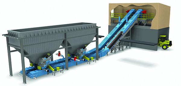
The Circumix DSS is a viable option for both new and existing disposal facilities. It processes combustion residuals from an extensive spectrum of coal qualities and from a wide variety of combustion systems. DSS can process various residuals—including bed ash, coarse ash, and fly ash—by mixing them with water to produce homogeneous slurry. This water can also originate as wastewater from the power plant. Other power plant byproducts, such as gypsum from the flue gas desulfurization (FGD) process, can be added to the slurry.
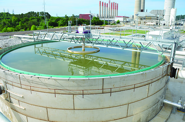
The core technology component is the Circumix mixer (Figure 1), which implements a hydrodynamic mixing principle. The mixer does not use mechanical agitation, such as paddles or stirrers, but uses the impulse of the flowing matter to transfer the mechanical energy needed for mixing. Pumps circulate the slurry with the proper velocity, and mixing is done in the pumps themselves and in the turbulently circulating fluid.
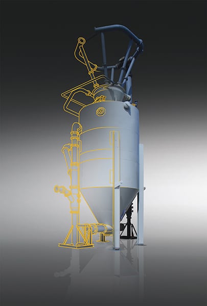 |
| 1. Hydrodynamic mixing. The core component of the Circumix Dense Slurry System is the mixer tank. It is employed to mix roughly 0.9 to 1.1 part of water with 1 part of ash (depending on the properties of the combustion residuals). Courtesy: GEA EGI |
The solid-to-water ratio in a lean slurry system is typically 1:10–20, whereas in dense slurry it is approximately 1:1. Hydrodynamic mixing produces a very homogenous mixture that maximizes the availability of reactive ions in ash products and results in near-stoichiometric use of the water contained in the slurry. This requires careful preliminary testing, as all ashes differ in chemical composition. Test results allow us to calculate the optimum setting.
Because the system features no mechanical agitation, power demand for the mixing process is low, and maintenance of the mixer is simple.
The number of mixers needed primarily depends on the number of units and plant availability requirements. Because the ash system is an auxiliary system, a failure of the mixers or any other ash-handling components would cause a trip of the power plant or one of its units, which could not be tolerated. Consequently, a high degree of reliability/availability usually is required. The standard solution is to provide a dedicated mixer to each unit and install an extra mixer for each two units as a common backup. It is not uncommon to provide 100% backup for each unit.
Safe operation is further increased by installing redundant capacities for the transport systems (backup transport pump trains and extra transport pipelines). Normally, the option of switching between mixers and pump trains and pipelines is provided so that each component can work with any other components.
A further consideration in defining the number of mixers and capacity of the transport system is a plant’s load pattern. Baseload plants are simpler, but a load-following plant may find it necessary to install a smaller-capacity system and a larger-capacity one. That is especially true for the transport pipelines, where the velocity of the flow must be kept within a relatively narrow range. Mixers typically can be controlled in a 30% to 110% range.
The solids-to-liquid ratio is determined by the physical and chemical properties of the solid particles and is automatically controlled to maintain optimum viscosity and low-energy transport. Defining this optimum ratio is the key to producing a mixture that contains just enough water for the chemical processes and mineral transformations. The process starts as a wet system (though with much less water than conventional slurry systems) but ends as a dry system, with the additional benefit of the favorable properties of the cured end-product: low hydraulic conductivity and nondusting nature.
The dense slurry is transported to the disposal facility via pipelines with relatively small diameters, in which erosion is minimized due to particles kept in suspension in the viscous slurry.
The landfill is divided into cells—at least three, but optimally four. Discharge is always to one cell at a time. When one cell is filled up, the discharge stops and starts at another cell while earthworks and elevation work is carried out at the cell that is full.
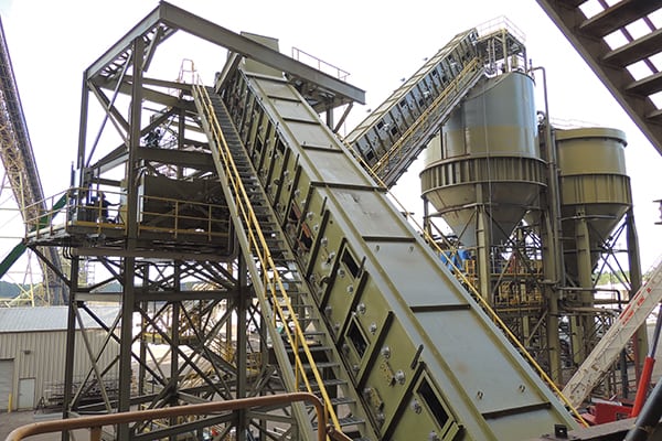
These cells are large areas with several discharge points, some 70 to 75 meters from each other, that are alternated on a roughly weekly basis. Shifting the discharge points also ensures that the impoundment is filled evenly. When discharged, the fresh slurry spreads in a thin layer over the solid deposit, which does not subject the dikes to hydraulic stress (Figure 2).
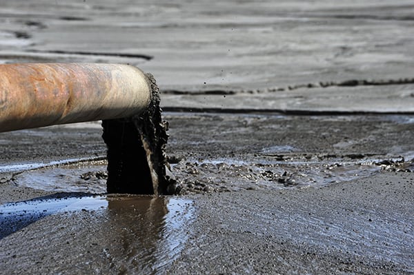 |
| 2. Slurry layers. After disposal, the slurry spreads in a thin layer and hardens within 24 to 72 hours. Courtesy: GEA EGI |
After disposal, the slurry solidifies—typically within 24 to 72 hours—and cures to form a solid, compact matrix in about 60 to 90 days. The solidification process is not disturbed by fresh slurry being discharged over the previous layer. In fact, the little excess water that may seep down from the fresh layer to the previous one may well feed the long-term (60- to 90-day or more) mineral transformations. The hardened slurry also significantly reduces the risk of releasing fugitive dust, compared with dry-handling systems.
There is very little free water, as most of the process water is either consumed in the hydration process or physically entrapped in the cured product. The little excess quickly evaporates. Because the hydraulic conductivity of the solidified slurry is low (measured values are 1 × 10⁻⁴ to 1 × 10⁻¹⁰ cm/sec), the risk of groundwater pollution is very slight.
Heavy metal dissolution is minimized owing to the enhanced metal sequestration properties of the material. Pollutants (metals) are not chemically bound in the end product; rather, the solid matrix structure retains the pollutants and prevents them from being dissolved by not allowing water (such as rainwater) to penetrate the deposited material.
Preparing a New Landfill Area
According to standard practice that complies with regulations in the European Union, natural geological isolation such as a clay layer is required under the disposal site. If such a geological structure is not available, an artificial substitute layer with similar mineral structure and leach performance must be installed.
In addition to this mineral layer, further artificial isolation is required, such as a geomembrane or HDPE sheet with lower hydraulic conductivity than the natural layer. This geomembrane is covered by a drainage system consisting of a gravel layer and perforated drain pipes. The gravel bed is protected by a geotextile cover that filters out fine particles to prevent the gravel from clogging.
The end product of the DSS system is very suitable for constructing such state-of-the-art landfills at reduced cost. Dikes enclosing the disposal area can be constructed from the cured disposed material itself, and because the material allows the construction of high, multi-tier landfills, the overall area required can be smaller.
Comparison of Ash Disposal Systems
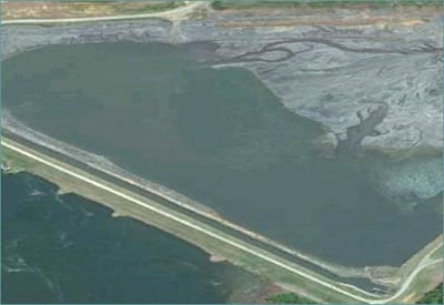
Traditional coal ash disposal systems are being phased out soon, owing primarily to disadvantages that include environmental hazards such as pollution of ground and surface waters, as well as fugitive dust commonly attributed to lean slurry ash handling.
Another major drawback is their unfavorable economy of operation. Lean slurry contains roughly 10 to 20 parts of water to 1 part of ash. The result is large quantities of wastewater that must be treated and discharged and large pumping power demand. Traditional slurry also poses risks to the environment if accidentally released, as has been seen most recently in the U.S. with the 2008 Kingston ash spill and this year’s Dan River ash release. Due to the very lean conventional mixture, no mineral transformation occurs. The end product is therefore a loose, sand-like material that easily carries with the wind and is easily penetrated by rainwater, which can dissolve various pollutants.
The GEA Circumix DSS typically uses 1 part of water to 1 part of ash. Most of the water is either consumed in the stabilization process or retained in the porous solidifying material. The capillary forces and low hydraulic conductivity of the cured slurry product significantly reduce leachate quantities, and the sequestration of metals reduces their concentration in the leachate.
DSS also offers several advantages in comparison to dry ash-handling systems. Dry ash handling is not in fact dry; such systems mix approximately 10% to 15% water in the ash to achieve a nondusting, transportable material. Sprinkler systems or other wetting methods are also often installed and used at disposal sites for dust suppression. This requires significant amounts of water but does not contribute to slurry stabilization.
Leachate water, if any, can be reused for the GEA DSS. High levels of operational safety mean no risk of spills, no dust hazard or groundwater pollution, no use of heavy machinery, easy landfill management, and low wear and tear on mixing equipment.
Cost Effectiveness
Due to the speed-controlled pumps employed for hydrodynamic mixing and transport in the system, the DSS operates efficiently under both part-load and full-load conditions of the power plant. Transport of ash to the landfill via pipelines is energy efficient, more environmentally safe, and less expensive than via conveyor belts or transport by trucks.
Operation of the DSS is fully automatic and can be supervised from a central control station. This means that fewer staff are required than for typical ash-handling systems. In addition, support services such as spreading/compaction by heavy equipment, lighting, manned security, and operators are not required at the disposal site.
A further benefit arises from the use of wastewater—typically plant wastewater such as blowdown of wet cooling towers or FGD wastewater—which can reduce costs for disposal or treatment of such water. Freshwater is not necessarily required.
Because the GEA DSS enables disposal facilities with relatively steep perimeter walls, the total space required for disposal can be reduced.
The DSS also can provide solutions for old lean-slurry ash pond closure requirements. The favorable properties of the solid final product (including compressional strength measured from approximately 13,000 to 166,000 lb/ft2) enable it to act as a capping layer for a drained lean slurry pond. Final closure of a disposal facility in this way can significantly reduce costs and long-term environmental risks.
Plant Experience
Power plant operators in several countries—including Hungary, Romania, India, and the U.S.—have chosen the Circumix DSS. By 2012, plants in these countries used the system to dispose of approximately 50 million cubic meters (m3) of dense slurry. Some reference projects in Hungary have employed the Circumix DSS since the 1990s. The most important benchmark reference there is the Mátra Power Plant.
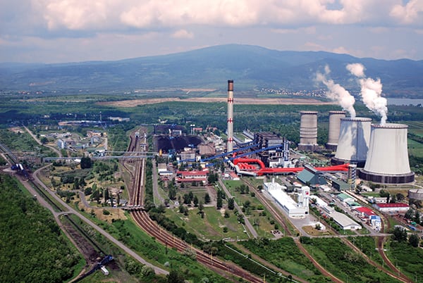
The five-unit, 884-MWe (gross) Mátra Power Plant’s coal units are primarily lignite-fired (Figure 3). The complex, located in Hungary, uses approximately 8 million tons of lignite per year, with a heating value of 7,000 kJ/kg on average. The plant operates a wet FGD system that produces gypsum and FGD water. The plant is subject to the following European Union requirements:
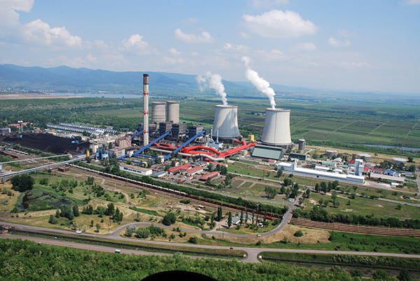 |
| 3. Hungarian early adopter. At Mátra Power Plant the Circumix dense slurry system has been in operation since 1998. After disposal of more than 22 million tons of fly ash, bottom ash, and gypsum, the operator invested in a second disposal area, sufficient for use until 2025. Courtesy: GEA EGI |
- Council Directive 1999/31/EC (European Commission) on the landfill of waste.
- Directive 2006/118/EC on protection of groundwater against pollution and deterioration.
- Commission Decision 2000/532/EC replacing Decision 94/3/EC, establishing a list of wastes.
The Circumix system has operated at this plant without difficulty since 1998, with two mixers in operation and two on standby. The residuals to be disposed of consist of fly ash, bottom ash, and—after a major upgrade in 2000—FGD gypsum.
The mixers receive 160 tons of dry solids hourly. Unlike some other systems, there is no concern regarding the temperature of the solids. The solids-to-water mixing ratio is roughly 1:1, the density of the slurry is kept at 1.35 t/m³. The transport flow rate is 240 m³/h, which is managed with two centrifugal-type slurry pumps per transport line, connected in series.
During its roughly 16 years of operation, the Mátra Circumix system has safely disposed of more than 33 million m3 of dense slurry. Over that time, a 1-square-kilometer area was filled, layer by layer, reaching a final height of 35 to 40 meters. The impoundment consists of 15 tiers with an average height of roughly 3 meters each.
The new operational landfill area is 60 acres in size. It complies with all European landfilling standards pertaining to bottom isolation, draining, and leachate collection, as described above. This more recent disposal area is designed to be sufficient until expected final closure of the power station, which is scheduled for 2025 (Figure 4). ■
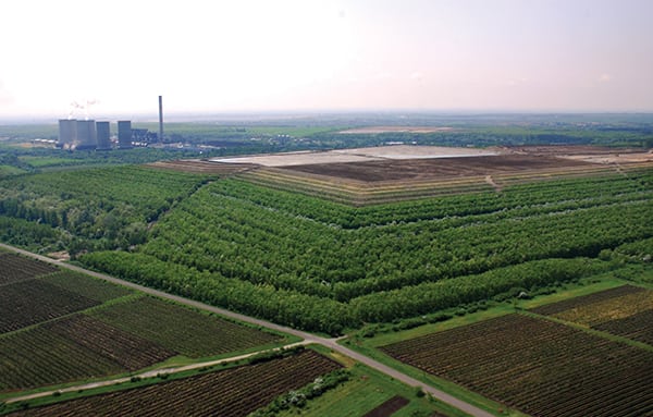 |
| 4. Tiered disposal. At the Mátra Power Plant landfill area, because DSS ash disposal is not endangering surface water or groundwater, cultivated farmland and vineyards are in immediate proximity to the landfill. The ash disposal facility is now approximately 35 to 40 meters high and contains almost 18 million cubic meters of solidified ash stone. Courtesy: GEA EGI |
— Lili Kranitz, MSc. (lili.kranitz@gea.com) is an environmental economist at GEA EGI Contracting/Engineering Co. Ltd.