In part because they are closed-loop systems, it can be easy to ignore power plant cooling water systems that support the reliable functioning of everything from stator bars in the generator to critical pump bearings for feed pumps and heat exchangers on air compressors. Proper monitoring and maintenance of these water systems can help you avoid more-costly repairs to the mechanical systems they cool.
There may be multiple closed-loop cooling systems at your power plant. Chances are good that they cool or control temperature on some very critical components. The two that are most likely to exist are the so-called bearing cooling water system (which takes care of more than just bearings) and the stator cooling system, for those plants that have a water-cooled stator. Closed-loop cooling systems can also be found in air coolers on the intakes of combustion turbines.
By its very nature, when a closed-loop system remains closed and operates properly for an extended period of time, it is often forgotten—or at least neglected. Small changes in the chemistry or the flow rates and differential pressures throughout the system may not be noticed. However, once corrosion processes get a foothold in these systems, it can be very difficult to correct them. In the meantime, critical data equipment may be damaged to the point where it affects the ability of the plant to operate.
We begin with some general principles and practices for closed-loop cooling water systems before looking at the stator cooling water system, which is a special case.
Understanding Closed-Loop Cooling Systems
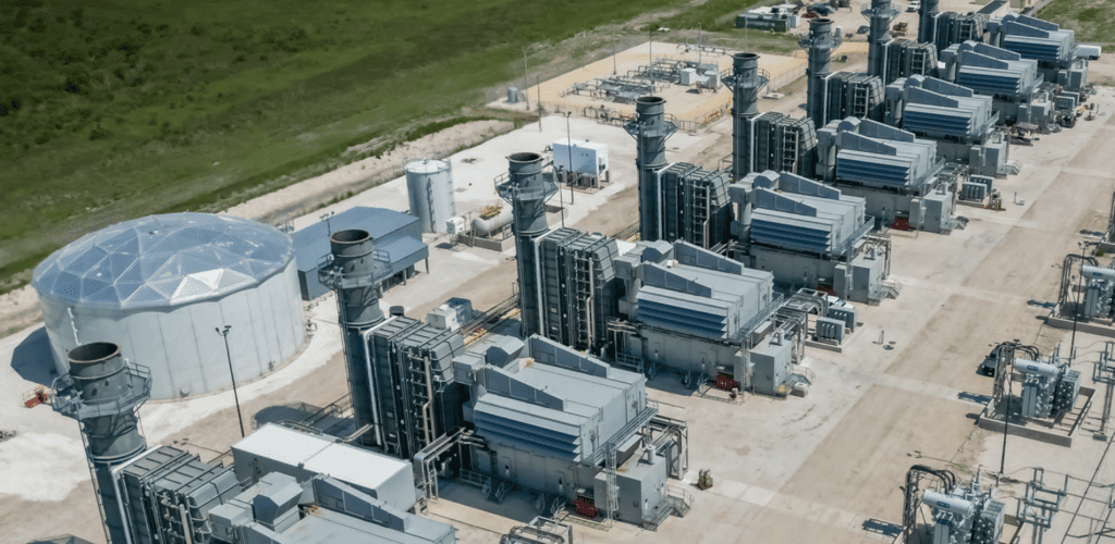
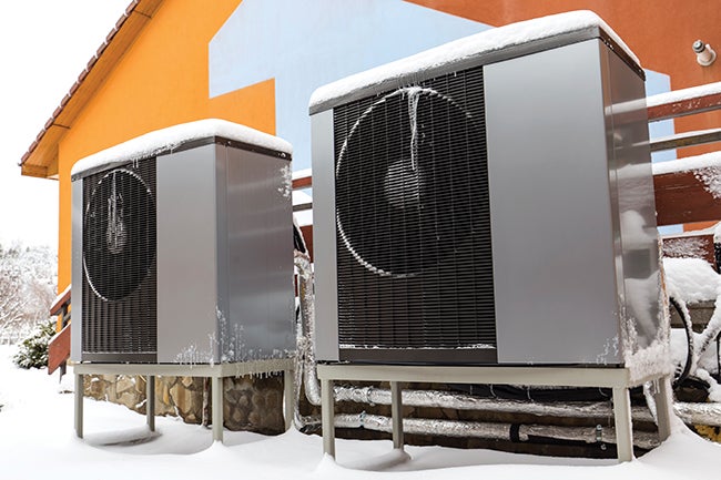
Most power plants using closed-loop water cooling for mechanical systems (rather than for the steam cycle) have several subsystems. The bearing cooling water system generally provides cooling for critical pump bearings and seals, hydrogen coolers for the generator, lube oil, and air compressor coolers. Other closed-loop cooling systems can include chilled water systems for air chillers used at the air inlet to the gas turbines at a combined cycle power plant and the chemistry sample panel.
A closed-loop cooling system can exchange heat with the main cooling water system in conventional tube and shell heat exchangers or plate and frame heat exchangers. Chilled water systems (air chillers) exchange heat with the compressor, which in turn uses a cooling tower to throw heat back into the environment.
Generally, demineralized water is used for closed-loop cooling water makeup, but chemical treatments are required to prevent corrosion and, in some systems, freezing. Most commonly, the piping in a closed-loop system is carbon steel. Heat exchange surfaces, such as air chiller assemblies, may be copper or even aluminum. Plate and frame heat exchangers are often made of stainless steel plates. Care and keeping of these systems requires that you pay attention to all the metals.
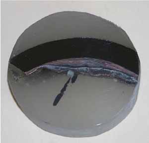
In a closed-loop system, oxygen pitting is the most common type of corrosion (Figure 1). Symptoms of oxygen pitting may be rusty water or recurring maintenance on bearings due to the abrasion caused by the corrosion products against the seal surfaces.
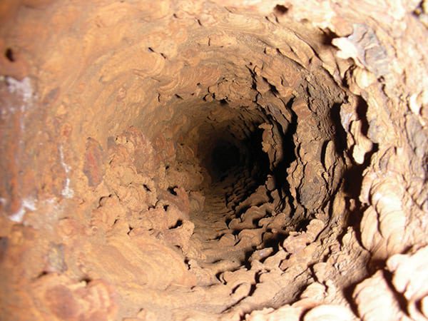 |
| 1. Oxygen pitting in a closed-loop cooling water system. Courtesy: M&M Engineering |
In order for oxygen pitting to occur, there must first be a deposit that covers a portion of the metal surface, creating a differential between the oxygen content underneath the deposit and the oxygen content in the bulk water. The oxygen-deficient area underneath the deposit becomes the anode, and the area around the deposit that is exposed to the bulk water becomes the cathode. This “big cathode, little anode” configuration causes concentrated and accelerated pitting in a confined area, producing pinhole leaks.
If bacteria are allowed to propagate inside the closed-loop system, they can create a “living” deposit. The byproducts of bacterial respiration are often acidic, and respiration also consumes oxygen, causing the base of the biofilm to be conducive to corrosion of the base metal. This further encourages some types of bacteria, as they use the oxidized metal in their metabolism.
Chemical Treatments for Closed-Loop Water Cooling
When a closed-loop cooling system is tight—experiencing no water loss—the chemical treatment that is applied can last for weeks or months before it needs to be refreshed. This can lead to complacency. On the other hand, closed-loop cooling systems that have leakage—and which have significant water loss—can be nearly impossible (and sometimes very expensive) to maintain at the proper treatment levels. Improper treatment levels will always lead to corrosion of these systems.
Below we list of few options that you can successfully use for treating closed-loop cooling systems such as the bearing cooling water system or closed-loop air chiller system. Generally, you find a treatment program that works well for the various metals in your system and system requirements (for example, determine if you need freeze protection) and then stick with it.
Regardless of which of the three chemical treatments you choose, they are likely to also contain pH buffers (caustic and sodium borate are common) to maintain an alkaline pH, which is conducive to minimizing corrosion in carbon steel. If there is copper in the closed-loop system, an azole may be added to the treatment to maintain a protective chemical layer on top of the exposed copper metal surfaces.
Sodium Nitrite. Sodium nitrite has been in use for many years to prevent corrosion in a wide variety of closed-loop systems. Nitrite is an oxidizer and essentially stops corrosion by “corroding” everything evenly. This seems counterintuitive, but when everything becomes the cathode and there is no anode, corrosion stops.
A constant supply of nitrite in the system ensures that any bare spots that are created quickly become passivated. However, if there is insufficient nitrite in the chilled water loop, an anode can form in the piping, and again we have the big cathode/little anode corrosion cell. The general guidelines for nitrite-based treatments are for a minimum of 700 ppm of nitrite.
Nitrites are utilized by some bacteria as an energy source. If the closed-loop system becomes contaminated with these bacteria, the nitrite level can decrease rapidly. The bacteria also generate biofilms, which create deposits producing areas that are anodes to the rest of the piping. Adding more nitrite only further accelerates the reproduction of the bacteria, making the problem worse. Systems using nitrite should be regularly tested for the presence of bacteria. In some systems, nonoxidizing biocides such as glutaraldehyde or isothiazoline are added to the treatment to prevent bacterial growth.
Sodium Molybdate. Sodium molybdate is generally classified as an anodic oxidizing inhibitor. Molybdate works with the dissolved oxygen in the water to form a protective ferricmolybdate complex on the steel.
Molybdate treatment levels can be anywhere between 200 ppm and 800 ppm as molybdate. Closed-loop systems that use demineralized water makeup would tend to be on the lower end of this range. Unfortunately, the world supply of molybdate metal tends to be concentrated in areas of historical political unrest, and over the years, molybdate prices have varied dramatically. That price variability can make molybdate treatment competitive with nitrite—or far more expensive.
Ironically, in closed-loop systems that are very tight, dissolved oxygen levels can drop, and thus minimize the effectiveness of a molybdate treatment (which requires dissolved oxygen to form a passive layer). Experts recommend a minimum of 1 ppm of dissolved oxygen in molybdate-treated systems.
Polymer Treatments. Polymer treatments have been used for many years to prevent scale and corrosion product accumulations in open cooling towers. Similar polymers are also now sold for use in closed-loop systems. It appears that the polymer acts as a dispersant for any corrosion products or scale that might form, so it prevents corrosion by keeping the surface clean and ensuring that any dissolved oxygen in the water attacks all surfaces evenly. This produces a general, but overall low level of corrosion.
One of the advantages of this treatment is that it is thought to be very environmentally benign, although as long as the closed-loop system remains closed, there should be no impact on the environment.
Monitoring Closed-Loop Cooling Water
Key to keeping your closed-loop system functioning properly is regular monitoring. Whatever the active agent is in your treatment (nitrite, molybdate, or polymer) the concentration must be regularly monitored. Generally, weekly testing is sufficient unless the levels of the treatment are dropping. (You won’t know that if you are not monitoring regularly.) Because the carbon steel and copper corrosion treatment are typically blended into one product, low levels of treatment may affect more than just the carbon steel piping.
The pH of the water should also be tested regularly. Considering the amount of pH buffering in chemical treatment, the pH of the water should be rock solid. Drops in pH may indicate bacterial contamination, particularly with the nitrite-based treatments. Another thing that can drop the pH is leaks in the system, which bring in fresh demineralized water makeup.
Be on the lookout for other signs of bacterial contamination, such as slimy growth in any sightglass or flow indicators, or septic smells when the sample is collected. Plate and frame heat exchangers have a very large surface and small spacing for heat exchange between the plates. Bacterial contamination can not only seriously affect heat transfer, but it also can cause pinhole leaks in the stainless steel plates. Depending on the pressure of the closed-loop versus open-loop system at this point, the bearing cooling water may leak out, or the open cooling water may leak in.
Remember that it is much easier to prevent bacterial contamination than it is to try to recover from a system that is severely contaminated.
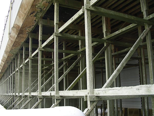
Stator Cooling Water Systems
The stator cooling water system is a very special closed loop for a couple of reasons. First, it protects one of the most critical pieces of equipment—the generator. There is only one metal of concern in this system: copper. And this system must remain very clean, even pristine. Small temperature increases in stator cooling bars can restrict load on or even shut down the generator. Therefore, this system requires special understanding, attention, and monitoring (Figure 2).
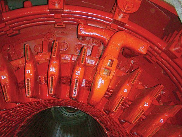 |
| 2. Critical cooling. Given the importance of the generator, its cooling water system deserves special attention. Courtesy: M&M Engineering |
Stator cooling water is contained in a closed-loop system that cools the copper stator bars in water-cooled generators. The copper coils contain hollow strands in the stator bar through which the cooling water travels (Figure 3). The ends of the stator bars are often bent to fit the generator configuration.
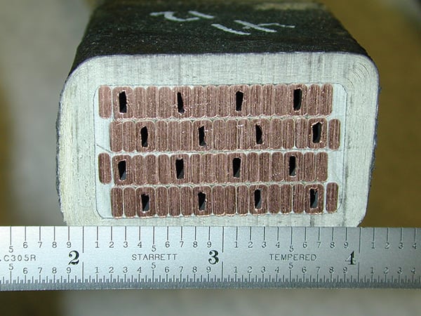 |
| 3 Narrow passage. Stator cooling water flows through the narrow channels of the stator bar. Courtesy: M&M Engineering |
Throughout the stator bars, the copper strands, including those that contain stator cooling water, change position in the bar itself. For example, hollow strands for cooling water flow may be in the top right-hand corner of a stator bar on one end and come out somewhere in the middle of the stator bar on the other end. These changes in position of the strands in a single bar are referred to as Roebel transposition and are done to reduce circulating electrical currents in the stator bars.
The narrow passages, bends, and twists in the hollow copper strands, including those caused by the Roebel transpositions, create many places for small amounts of mobile corrosion products to partially or completely block the cooling water’s path (Figure 4), causing the stator bar to overheat. Overheating of stator bars can result in reduced generating capacity or even catastrophic failure of the generator.
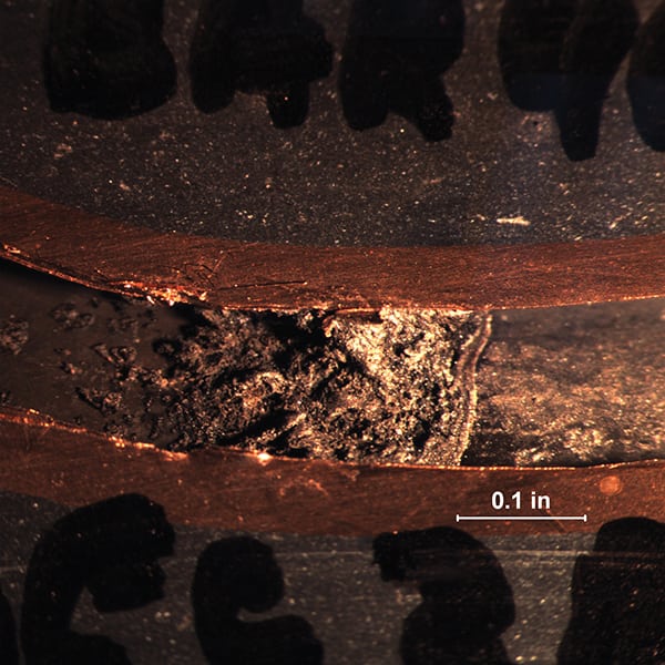 |
| 4. Plugged. Given the narrow path for water in stator cooling bars, it doesn’t take much corrosion material to plug them. Courtesy: M&M Engineering |
A stator cooling water system contains the following components:
■ A head tank containing the deionized water that provides suction to the pumps
■ Circulating pumps
■ Heat exchanger
■ Filters (cartridge filters, mesh strainers, or both)
■ Mixed-bed deionizer
■ Monitoring for flow, temperature, conductivity, dissolved oxygen, and, in some cases, pH
There are often two deionizer vessels and two sets of filters to allow one to be valved out to replace the filter cartridge or for replacement of the mixed-bed resins.
The cooling loop removes heat from the stator bars and conveys it away through heat exchangers. The water is continuously passed through a mixed-bed polisher that removes any soluble ionic contaminants that enter the water. These impurities are generally dissolved carbon dioxide and ionized (dissolved) copper corrosion products.
The ion exchange resins may also trap fine particles of copper oxides, though this is better done by the cartridge filters. The ion exchange resin can become exhausted over time (as indicated by increasing conductivity). But it is more common for differential pressure across the resin bed (caused by the collection of corrosion products in the resins) to require the resins to be replaced.
The Problem of Copper Corrosion in Stator Systems
The stator cooling water system’s heat transfer surfaces are generally pure copper. The chemistry of copper in oxidizing and reducing conditions has been the subject of a great deal of research, and we have a better understanding now of the conditions that cause corrosion, which is a common problem.
In the presence of high-purity water, under low–dissolved oxygen conditions (<20 ppb), copper forms a passive layer of cuprous oxide (Cu2O). Cupric oxide (CuO) can be formed when dissolved oxygen is high (>2 ppm). Either of these oxides can be stable and create a passive oxide layer on the channels in the stator bars. A slightly alkaline pH increases the stability of either oxide layer.
A significant change in the dissolved oxygen changes the electrochemical potential of the water. This can cause the copper oxide to be converted from one form (cupric) to the other (cuprous). During this conversion, the oxide layers become unstable and will be released into the water, where they move downstream and reattach to another area. Depending on the current condition of the water, as they reattach, the deposits may contain either of the two copper oxides mentioned above or copper metal. This reattachment may take a number of forms. Figure 5 shows copper oxides that have deposited out in a feather-like structure on the copper surface. Figure 6 shows the rough and random nature of deposits in the channel.
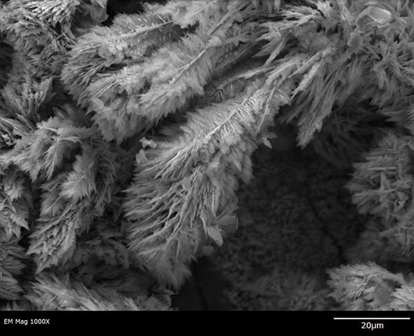 |
| 5. Copper oxides. Feather-like copper oxide structures are typical of low–dissolved oxygen, neutral pH conditions. Courtesy: M&M Engineering |
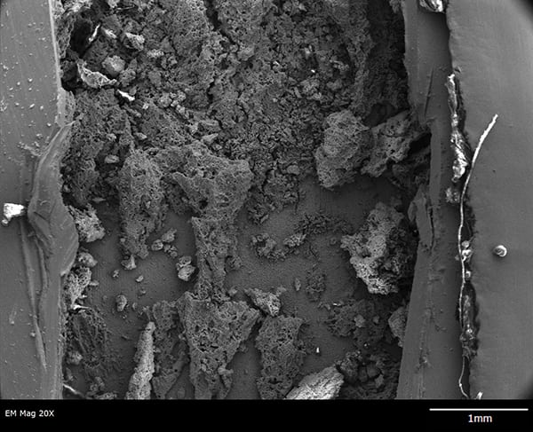 |
| 6. Random deposits. Deposits like these inhibit flow through the cooling strand in the stator bar. Courtesy: M&M Engineering |
It is important to understand that it is not necessarily the corrosion of the stator bar per se that creates the problems. With such pure water conditions, the pits created by any localized corrosion are very small. The problem is the release of the copper oxides from one area that collect in another. The copper “corrosion” rate can be very low, but conditions that accelerate the rate at which the copper oxide is released into the water can be very detrimental to the condition of the system. The release rate of the copper oxides may also be affected by pH and by temperature.
There is somewhat of a vicious cycle effect here. An increase in the stator cooling water temperature increases the release rate of copper oxides into the water. Deposits and partially plugged strands can reduce the water flow rate. The slower the water travels through the stator bar, the warmer it becomes. This cycle can cause a stator cooling problem to come out of nowhere.
The best way to avoid problems of copper corrosion and keep the stator bars flowing and cool is to know what treatment option you are going to use and to monitor the stator water-cooling system appropriately.
Monitoring Stator Water
Unimpeded flow through all stator bar openings is critical to operation of the generator and minimizing the transport of particles into places where they can cause blockage. That’s why stator cooling water should be continuously monitored for conductivity and dissolved oxygen. The conductivity is critical and generally is kept below 0.5µS/cm. (Your original equipment manufacturer may have different limits.)
Monitoring the health of stator water systems includes not only the chemical parameters like dissolved oxygen and conductivity. It also involves looking at a variety of related temperatures and pressures for trends that can predict an approaching problem.
Online (in-situ) monitoring for conductivity and dissolved oxygen is recommended in stator systems. Grab sampling is not usually done due to the amount of water required to flush out sample lines before one can be sure of getting an accurate sample, which then needs to be replaced. This can be a problem.
The pressure differential across the cartridge filters and the mixed-bed deionizer are also important. The frequency with which the filter needs to be changed, due to particulate plugging, is an indication of corrosive conditions in the system. Not changing the cartridge filters or replacing the demineralizer resins when the differential pressure calls for it will accelerate the plugging of the stator bars. The recommendation is to replace the demineralizer resins if the conductivity exceeds 0.5µS/cm or if the pressure differential across the deionizer exceeds 15 psid. As a precautionary measure, the resins should be changed every 18 months to two years.
Cartridge filters that are normally supplied are 5µm, and some plants have found that moving to a 1µm cartridge filter is helpful. Any particles that are trapped by the filters or by the deionization resins are particles that cannot reattach to the surface of the stator cooling channel.
Monitoring the makeup water usage in a stator cooling system is also important. If the system is operating under a low–dissolved oxygen regime, makeup water brings in the only dissolved oxygen but also carbon dioxide that will lower the pH of the stator cooling water and increase copper oxide release rate, which will accelerate temperature problems.
Similarly, if there is a significant pressure drop across the deionizer or across the cartridge filters, or there are issues with the stator cooling water pumps, these can all slow the flow of the stator cooling water through the system, accelerating the release of the copper oxide and increasing the potential for plugging.
Choose Your Treatment Option and Stick with It
In a previous article we discussed treatment options for stator cooling water in more detail (“Forgotten Water: Stator Cooling Water Chemistry” in the December 2007 issue of POWER). Of those power plants that have water-cooled stators, there is almost an even split of high- and low-oxygen regimes, with the slight numerical advantage to those operating in the high–dissolved oxygen regime.
High dissolved oxygen requires maintaining greater than 2 ppm of dissolved oxygen in the stator cooling water at all times. This forces the copper to the CuO form of the oxide and maintains the passivation layer with very little release of oxide into the cooling water. Any level below 1 ppm should generate immediate action to correct the problem. Often just leaving the head tank vented is sufficient to keep the stator cooling water oxygenated, but if hydrogen leaks into the cooling water, it can displace the oxygen and cause corrosion. The open head tank also allows in carbon dioxide, which can lower the pH of the stator water, increasing corrosion. Some plants put carbon dioxide absorbers on the head tank vent to remove it, before the air enters the tank.
Operating a low–dissolved oxygen regime requires that the stator cooling water always maintain less than 20 ppb of dissolved oxygen, and ideally as low as possible. This generates the Cu2O passive layer but over a longer period of time. The formation of the cuprous oxide is limited by the amount of dissolved oxygen in the water. Low dissolved oxygen can be maintained by keeping the system leak free to limit the amount of makeup water. Oxygen may also leak in through flanges, pumps, and seals. In some cases, oxygen leaks in through a loose connection or flange that creates a venturi effect, sucking air in. Some plants blanket the head tank with nitrogen, or even hydrogen, to preclude any air. The low-oxygen condition needs to be maintained during major outages, and that may take some planning.
Increasing the pH of the stator cooling water also has been shown to be very effective at reducing copper corrosion and release rates. However, fewer utilities have opted to go for the extra steps required to create and maintain an alkaline pH.
Alkaline pH treatment can improve either the low– or high–dissolved oxygen regime. The target pH for the water is generally considered between 8.5 and 9.0 and may be obtained by adding small amounts of caustic to the water or by substituting sodium exchange resin for the hydrogen form cation resin in one of the deionizer vessels and metering the water through this exchanger until the pH reaches the desired level. ■
—David Daniels (david_daniels@mmengineering.com) is a frequent contributor to POWER and senior principal scientist at M&M Engineering Associates Inc.