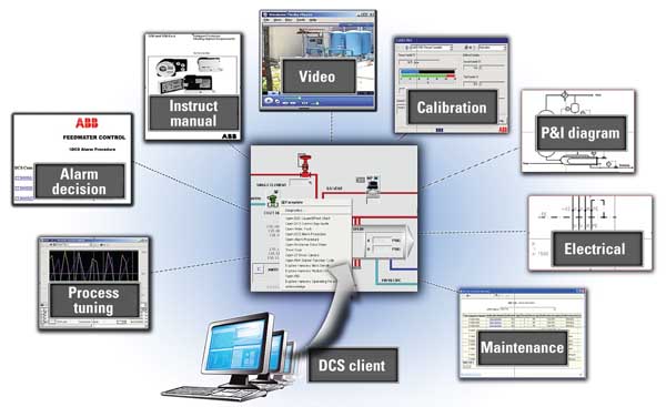
Modern distributed control system platforms can provide many tools to capture best operating practices and automate them. This case study shows the steps taken to automate a hypothetical simplified feedwater pump system for a combined-cycle power plant. It describes a combination of controls automation strategies and human-machine interface techniques designed to increase the overall level of automation while improving ease of use.
Modern distributed control system (DCS) platforms offer capabilities that were unavailable just a few years ago. Features such as integrated graphical engineering environments, simplified sequencing controls, and improved human-machine interfaces (HMI) make higher levels of automation more practical from the standpoints of implementation, maintenance, and ease of use. The timing of these advances couldn’t be better—critical operating personnel throughout the power industry are approaching retirement age, and there are insufficient numbers of skilled younger personnel to replace them. Leveraging the existing plant knowledge base to design automation that reduces the burden on plant operators will be essential to meeting tomorrow’s plant demands.
As an example, the following case study describes automating a simplified feedwater system for a combined-cycle power plant. The existing legacy DCS controls are proven and reliable; however, the sequence of operations and coordination of regulatory controls is not automated, therefore, it requires a high degree of knowledge and attention on the part of the operator. This case study describes a combination of controls automation strategies and HMI techniques designed to increase the overall level of automation while improving ease of use by operators and maintenance personnel. (Note: DCS examples were developed using the Siemens SPPA-T3000 DCS platform. A detailed description of this control system was included in “Upgraded Control System Adds to Merchant Plant’s Bottom Line,” January 2009, available at https://www.powermag.com.)
The “as-found” DCS graphics and controls strategy for this case study form the basis for comparison with newer strategies, so a brief discussion of the existing automation baseline is in order. The reference information used in this case study was provided by the Electrical Power Research Institute (EPRI) but also incorporates information taken from one or more operating plants.
The Hypothetical Plant’s Layout
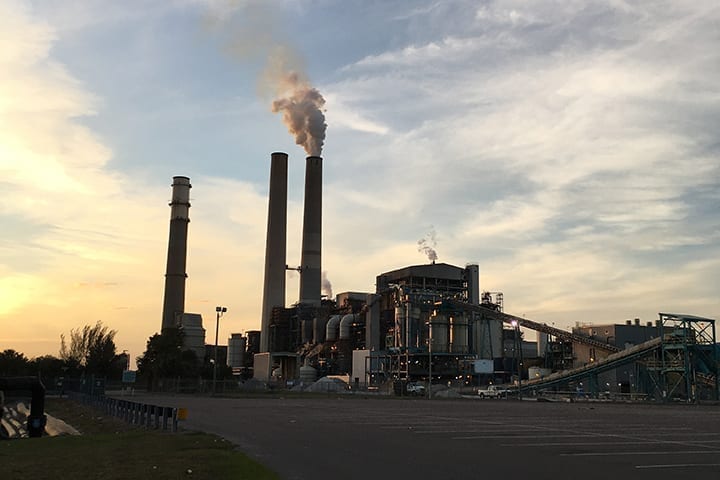
The hypothetical plant consists of two combined-cycle combustion turbines, each with a heat-recovery steam generator (HRSG). Both HRSG units are coupled to a single steam turbine with feedwater supplied from a common condenser and the hotwell, the receptacle for the hot water drawn from the condenser by the air pump.
Looking at a single HRSG, the feedwater train consists of a pair of 100% capacity feedwater pumps and a set of three drums for low-pressure (LP), intermediate-pressure (IP), and high-pressure (HP) steam headers. The feedwater pumps transfer feedwater from the LP drum to the IP and HP drums. Minimum flow through the pump is maintained by a recirculation line back to the LP drum with a modulating valve and a variable-flow setpoint calculated from the pump manufacturer’s operating curves. Both pumps share supply lines and valves to the IP and HP drums. Each pump is equipped with a variable frequency drive (VFD) for speed control and has a dedicated lube oil pump.
Existing Drum Level Control
Feedwater control to IP and HP drums consists of both single- and three-element drum level control. Single-element controls modulate the supply valve to each drum based on the level. Three-element control uses steam flow from the drum as a feedforward signal to a feedwater flow controller whose setpoint is modulated to maintain desired drum level. Pump speed is modulated to adjust IP and HP flows in coordination with the feedwater valves as follows:
- Control of VFD and feedwater valves applies regardless of single- or three-element level control.
- The VFD runs at minimum speed, modulating the IP valve to maintain IP drum level and the HP start-up valve to maintain HP drum level until the HP start-up valve is fully open.
- Once the HP start-up valve is fully open, the VFD will modulate to keep the IP valve within its control range (<85%).
- If the IP valve is <85% open, modulate the IP valve to maintain IP drum level and modulate the VFD to maintain HP drum level.
- If the IP valve is >85% open and the HP start-up valve is fully open, increase the VFD speed until the IP valve output is <85%. Modulate the HP main feedwater valve to maintain the HP drum level.
Existing Baseline HMI
The existing operator interface for each feedwater train consists of three full-screen graphics. The first is a partial schematic of the feedwater system, showing pumps and discharge lines, but not the drums. The second graphic is a collection of control faceplates for use in setting up discrete devices and regulatory controls. The last display is a tabular collection of relevant plant operating data, including feedwater pumps and drum conditions. Each feedwater pump has numerous process interlocks that are not immediately accessible from the HMI.
Case Study Assumptions
The assumptions for this case study are as follows:
- Only normal operation is considered (no power augmentation).
- Pump failure will start the standby device without cycling common discharge valves.
- Shutdown will stop all pumps and close all valves in the feedwater system.
- VFD and feedwater valve coordination as supplied on the piping and instrumentation diagram appears incorrect. The original operation as stated above is an interpretation.
Proposed Control Strategies
Operators and maintenance personnel can use a number of control strategies to improve the operation of their facilities’ feedwater pump systems.
Open-Loop Control. There are many possible methods of automating boiler feed pump systems. The method chosen minimizes the number of sequences so the operator can easily follow the actions of the automation system. This becomes more important as the whole power plant is automated. The sequence is used to place equipment in service and place closed-loop controls in the relevant modes, such as filling, start-up drum level, and normal drum level control. The protection logic is carried out directly at the device drive level. A basic principle is that the operator has the option to control at all times.
Any field equipment loss of status during start-up after being placed in service (such as the isolating valve open status being lost) should be handled as a status discrepancy on the device. The affected closed-loop controls utilize the process values (feedwater flow and isolating valve not closed) to maintain their operation. The plant protects itself through the process values (drum level trip).
On this basis, reversing sequences are not recommended as a best practice. Instead, the sequence design utilizes check-backs from the process (such as pressures and flows) and device check-backs as the sequence feedback for overrides and step criteria. If a sequence is restarted, fulfilled criteria or override check-backs bring the sequence back to point of action required immediately. As a result, status discrepancies can be used to stop the sequence and allow the operator to investigate the fault and restart the sequence without unnecessary actions on the sequence or process.
The main automation structure for the feedwater pumps is given in Figure 1.The sequence for a feedwater system is controlled by a single subgroup control (SGC) block. The two feedwater pumps are, in turn, managed by a single device configuration overlay (DCO) block. Each motor has a separate motor block, with appropriate logic for permissives, interlocks, and automatic operation.
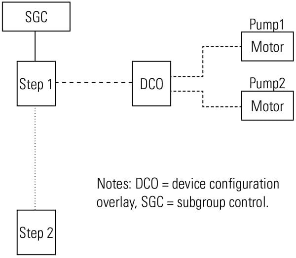 |
| 1. Automation hierarchy. This schematic shows the main automation structure for the feedwater pumps. The sequence for a feedwater system is controlled by a single subgroup control block. The two feedwater pumps are in turn managed by a single device configuration overlay block. Courtesy: Siemens Energy Inc. |
Sequential Logic. The sequence logic mirrors the steps and actions of the manual start-up sequence taken from a plant operating procedure. The complete sequence begins with no pumps running, first having the operator go through the required manual checks. Once the system is ready, the IP and HP drums are isolated, the recirculation path is opened, the lube oil pumps are started, and the selected pump is started. From this point forward, a pump failure will cause the DCO block to start the standby pump. In fact, the switchover logic will remain in effect even after the main sequence is complete. Steps match the written sequence for this example but could easily be consolidated for simplicity.
Shutdown. The shutdown sequence initiates the closure of the IP and HP feedwater and isolation valves as well as the feedwater and lube oil pumps.
Operator Prompts. As the sequence progresses, three single-line messages appear on the screen. The first line displays an operator prompt and acknowledgement button, if required. The second line is a description of the current step actions and conditions. The final line lists information related to the next step in the sequence. Figure 2 shows typical messages and an operator prompt.
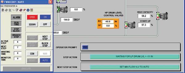 |
| 2. Friendly reminders. This figure shows typical messages and operator prompts. Courtesy: Siemens Energy Inc. |
HMI Concepts for Robustness
Several concepts built into the HMI have the goal of improving the operator interface: A single process graphic simplifies navigation as well as monitoring of the feedwater system; linked pop-up displays provide easy access to more detailed information; and a dedicated alarm summary displays a prefiltered set of alarms related to the feedwater system for faster reference.
Single Process Graphic. A single consolidated process graphic encompasses the major components of the feedwater system, including the LP, IP, and HP drums. Figure 3 shows typical messages and an operator prompt.
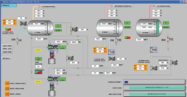 |
| 3. One-click convenience. A single consolidated process graphic encompasses the major components of the feedwater system, including the LP, IP, and HP drums. Courtesy: Siemens Energy Inc. |
Control is accessed by faceplates linked to each dynamic symbol. The sequence (SGC) and group (DCO) controls are linked here as well. A space on the page is reserved for operator messages and prompts during the sequence. Access to control settings, alarms, and the linked control diagram is given by the icons below the title bar. Linking to the online control diagram permits one-click checking of logic or permissive/interlock conditions.
Pop-up Displays. For major equipment such as a feedwater pump, it is sometimes useful to have a dedicated set of small pop-up displays, each linked to a button on the process display. Figure 4 shows several examples. The permissives listed in the EPRI case study have been assembled into a small pop-up overlay, along with a similar list of interlocks for each pump. Bearing temperatures and other pump/motor data are available from the data button.
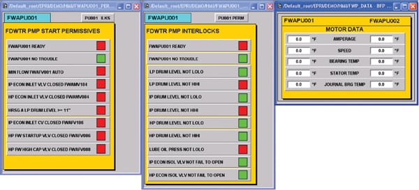 |
| 4. Pop-ups in a flash. For major equipment such as a feedwater pump, it is sometimes useful to have a dedicated set of small pop-up displays, each linked to a button on the process display. Courtesy: Siemens Energy Inc. |
Regulatory (Closed-Loop) Control
Single push-button start-up is not possible without stable regulatory controls. This stability is required not only during normal operation but also during start-up and throughout the full operating range of the unit. With this in mind, the coordination of the VFD and feedwater valves is revisited.
VFD Control Strategies
Provided stable operation is maintained, reducing pump load can result in significant energy savings. Assuming a plant electrical load of approximately 1.5 MW for the feed pump, a 10% reduction in pump load would save over 1,300 MWh annually.
The strategy as described for the case study uses the VFD in combination with the feedwater valves in an overlapping split range. The VFD starts at minimum speed (a 35% turndown from maximum). It increases as needed once the valves are at the upper end of their control range and only modulates while the IP valve is less than 85% open. One consequence of this strategy is a somewhat disjointed control response and an undesirable coupling of the IP and HP drum levels. For example, as the VFD speed increases, both the IP and HP valves throttle back in response to increased flow. Once the IP valve throttles below 85%, the VFD could remain above minimum speed indefinitely.
An alternative approach is to change the VFD strategy by introducing an override controller, as illustrated in Figure 5. For simplicity, a single output is used for the HP drum. This output could in turn be sent to each valve via a balancing control or simple split range. The IP drum level controls also are not shown in this scheme for simplicity but could also be added as an additional override.
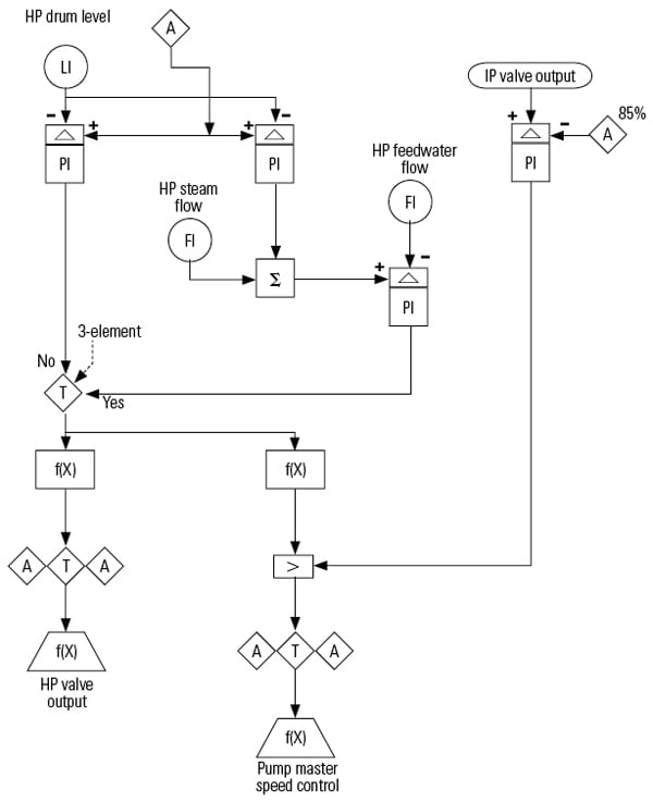 |
| 5. Easy overrider. Once the IP valve throttles below 85%, the variable-frequency drive (VFD) could remain above minimum speed indefinitely. An alternative approach is to change the VFD strategy by introducing an override controller. Courtesy: Siemens Energy Inc. |
The level control demand output for the HP drum, whether single- or three-element, is passed to both the HP valve and the pump VFD. As long as the IP valve stays below 85% open, this output is a simple split range, with the valve opening from 0% to 100%, then increasing the pump from minimum to maximum from 100% to 200%. A hidden direct-acting controller (error = process variable – setpoint) monitors the IP valve demand with a fixed setpoint. The output of this controller passes through the “high select” function to the VFD. As the valves respond to the increased flow by throttling, the override controller output returns to zero, which allows the HP valve to open completely and the VFD to modulate to maintain level. The master speed control drives the speed controls for both pumps.
This control scheme has the advantage of being simple yet efficient; however, it does retain some coupling between IP and HP drums. As a further modification, changing the override to a bias function and adding a decoupling function to this control strategy would minimize disturbances to HP drum level during override conditions. This modified strategy is illustrated in Figure 6. As in the previous diagram, the IP drum level is omitted for simplicity. To account for this, a second proportional integral controller would be added to the scheme with IP feedwater valve position as its controlled variable. The two positioning controllers would pass to the VFD via a high select, with decoupling biases to each valve.
 |
| 6. Curbing disturbances. Changing the override to a bias function and adding a decoupling function to this control strategy minimizes disturbances to HP drum levels during override conditions. Courtesy: Siemens Energy Inc. |
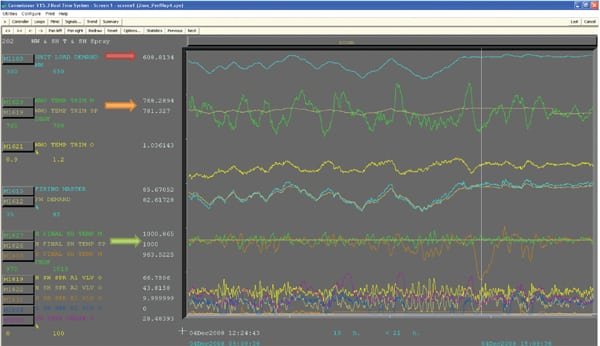
Process Aspects: Pressure Variations, Drum Swell, and Stability
During start-up, the drum level controls can be a challenge for any operator. The operator and controls have to contend with drum level shrink/swell; the drum level swings due to the interaction of the steam pressures and the drum levels. Providing stable drum levels is a key part of any full start-up automation.
Operators use different strategies to deal with the so-called “drum-level rodeo.” This sometimes entails continuous blowdown of the drums to ensure that the feedwater is continuously flowing, mitigating the effect of feedwater cycling and temperature differential between the water entering the drum and drum water/steam temperatures. However, this requires continuous attention by the operators.
Pressure variations also affect the drum level through the compressibility of the water-steam mix, and cause steam flow variation leaving the drum. This means any instabilities or cycling of the bypass systems are also reflected in the drum level. In addition, variations in the rate of pressure change affect the drum level. This effect is also utilized by operators when manually influencing the drum level.
Bypass strategies have been implemented that stabilize drum level controls, and pressure-raising strategies have been used to stabilize drum level for cold through hot starts. In addition, including the pressure dynamics in the drum level controls has proven to be a factor in stabilizing drum level controls during start-up. Proper tuning of the controls is also a must.
Because the boiler feed pumps usually supply water for attemperation of steam supply and bypass lines, changing the supply pressure may affect these temperature controls, requiring further coordination. One example might be a pressure control feedforward to the temperature controls; decreasing boiler feed pump discharge pressure increases spray water demand.
Simple, Yet Complex
Even a relatively simple start-up process can have many steps and delays for operator cross-checks. Automation can simplify the procedure for the operator while reducing start-up time. In addition, more sophisticated controls techniques may be applied to improve process stability, reduce energy usage, and increase operating flexibility.
This article was written based on case study guidelines provided by the Electric Power Research Institute. The control diagrams created for this case study are available in PDF format from the authors, via email request (george.thackston@siemens.com). Portions of this article were presented at the 2010 ISA POWID Symposium.
— Steven Leibbrandt (steven.leibbrandt@siemens.com), chief technology officer, and Bill Thackston (george.thackston@siemens.com), principal engineer, work for Siemens Energy Inc.