For more than a decade Babcock & Wilcox Power Generation Group Inc. and Air Liquide have been developing oxyfuel technology with the goal of using it to concentrate CO2 from pulverized coal-fired power plants and achieve up to 90% CO2 capture and storage. This technology was recently selected for demonstration as part of FutureGen 2.0.
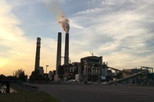
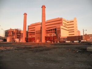
In late September 2010, the U.S. Department of Energy (DOE) signed cooperative agreements with Ameren Energy Resources, to construct FutureGen 2.0 using full-scale oxy-combustion technology on an existing coal-fired power plant, and with the FutureGen Alliance, for the design and construction of a CO2 pipeline and storage hub that will transfer and store the CO2 captured by the repowered plant. The project is set to “oxy-combust repower” a mothballed unit at Ameren’s Meredosia Power Plant located near Jacksonville, Illinois. Babcock & Wilcox Power Generation Group (B&W) and Air Liquide Process & Construction (AL) are among the partners in the development of FutureGen 2.0 (Figure 1). The new plant will be designed to produce 200 MW gross/140 MW net, capture 1.3 million tons/year of CO2 and emit near-zero NOx, SOx, mercury, particulates, and other hazardous air pollutants.
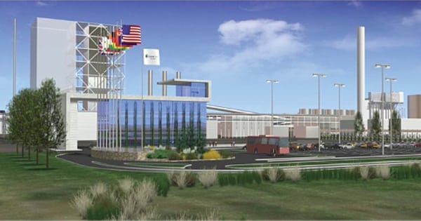 |
| 1. Future plans. This artist’s concept drawing of FutureGen 2.0 was presented by the FutureGen Alliance at an October 28, 2010, project briefing. Source: FutureGen Alliance |
B&W, AL, and the FutureGen Alliance are now working on completing Phase 1 of the project, which includes initial engineering and validation of the project’s scope, cost, schedule, and commercial viability. Phase 1 is expected to be completed in the third quarter of 2011.
Assuming that Phase 1 is found to be technically and commercially sound, Phase 2 will be authorized by the DOE for detailed design and collecting the numerous permits required to construct the project. Concurrently, Ameren will request that the Illinois utilities commission change current law to allow some form of cost recovery for the project. Phase 3 includes procurement of materials and construction of the plant, which will require the approval of the DOE and Ameren’s board of directors. DOE officials believe that Phase 3 could begin as early as mid-2012 and the plant could be in service and begin the 2.5-year test period in the first quarter of 2016.
Technology Development
There are currently three main options for capturing carbon from coal-fired systems: integrated gasification combined cycle (IGCC), post-combustion capture, and oxy-combustion. IGCC is a greenfield or repowering option that has long been favored for carbon capture and sequestration (CCS), but recent demonstration project costs have been much higher than anticipated, and performance estimates have fallen far short of expectations. Post-combustion systems using ammonia- or amine-based solvents hold promise for both new and retrofit applications, and several demonstrations are under way. Oxy-combustion—combustion of the fuel with a mixture of nearly pure oxygen and recycled flue gas rather than air—is predicted to have the highest overall efficiency and promises to be the low-cost option. Unlike post-combustion capture, oxy-combustion technology cannot be demonstrated on a slip stream from a larger plant (see sidebar).
Through participation in various consortia focused on this technology, B&W and AL have made major advancements in oxy-combustion and are currently two of the world leaders in this field. Together, B&W and AL performed pilot-scale oxy-coal combustion tests on a 1.5-MWth pulverized coal (PC)–fired boiler and completed several economic and performance studies of oxy-coal PC-fired power plants from retrofit to full-scale greenfield applications.
In late 2006, B&W modified its existing 30-MWth (100 MBtu/hr input) Clean Environment Development Facility (CEDF) for oxy-firing and in 2007 completed testing with bituminous, subbituminous, and lignite coals with the cold recycle process configuration. Further testing was completed in spring 2008 with the warm recycle process. Extensive study of several oxy-process configurations and heat integration options began in 2008.
Over the past two years, the team has completed the basic design of a 100-MW net demonstration plant and a 700-MW gross commercial reference plant using the oxy-combustion technology. In July 2009, B&W and AL, together with Black Hills Corp., proposed a near-zero-emission 100-MW net oxy-combustion demonstration plant to the DOE under its Clean Coal Power Initiative Round 3 solicitation. That project was not selected. However, given the positive results of the pilot-scale tests and the work completed on previous proposals submitted to the DOE for oxy-combustion testing, the oxy-combustion technology was selected by the DOE to become part of FutureGen 2.0.
As noted earlier, the FutureGen 2.0 Phase 1 design, cost estimating, and scheduling work is under way as of this writing, and we’ll report of the specifics of that design when that phase of the project is completed. In this article, we focus on the history and fundamentals of B&W’s oxy-combustion design.
Oxy-Combustion Is Ready for Demonstration
B&W first explored oxy-combustion technology in 1979 with hopes of using the CO2 stream for enhanced oil recovery, but low oil prices made it uneconomical. In the mid-1990s, as interest in CO2 emissions and their impact on climate change was increasing, B&W reconsidered the possibilities of the technology as a means of concentrating CO2 for storage or use. In 2001, B&W partnered with AL, which brought expertise in air separation, compression, and purification to the team. The team worked to improve the overall efficiency and economics of the entire oxy-combustion plant design. This collaboration led to several engineering studies and cost estimates for both retrofit and greenfield applications. That work included testing oxy-combustion at 1.5 MWth at the B&W R&D Center between 2001 and 2004 and large pilot-scale tests at the 30-MWth CEDF in 2007 and 2008.
What is Oxy-Combustion?
The oxy-combustion system consists of the familiar coal-fired power plant’s boiler and environmental cleanup equipment (in the case of FutureGen 2.0, supplied by Babcock & Wilcox). These components have been redesigned to burn coal with a mixture of nearly pure oxygen and recycled flue gas (which is primarily CO2) rather than air. An air separation unit (ASU) produces the oxygen used for combustion of the coal (Figure 2). The concentrated stream of CO2 that leaves the boiler is ready for cleaning and compression by the compression and purification unit (CPU). The CO2 is then transported in a pipeline to a permanent storage facility. For FutureGen 2.0, Air Liquide is supplying the ASU and the CPU.
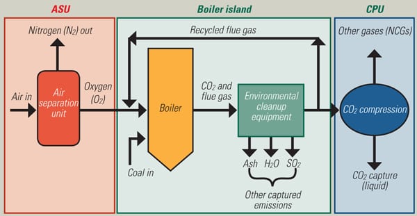 |
| 2. Three building blocks. The oxy-coal combustion power plant substitutes nearly pure oxygen mixed with recycled flue gas for air in the combustion of coal to produce a CO2 gas stream ready for cleaning and compression in the compression and purification unit (CPU). From the CPU the essentially pure CO2 is transported as a liquid via pipeline to the CO2 storage facility. Source: FutureGen Alliance |
The 30-MWth CEDF is a mini power plant that includes a specially designed boiler with a full complement of flue gas cleanup systems. The CEDF is “catch-and-release” system for CO2; although a high-purity stream of CO2 is produced by the oxy-combustion process, the CO2 from the pilot facility is not compressed and stored but is released to atmosphere. All of the other processes for flue gas cleaning were included as part of the system testing.
The CEDF was the first in the world to oxy-combust bituminous, subbituminous, and lignite coals at this scale. Two process configurations were tested:
- Cold recycle, in which all of the flue gas passes through the environmental clean-up equipment, is cooled to remove substantial moisture, and then is recycled to the boiler at approximately 150F.
- Warm recycle, in which the secondary flue gas is taken after the air heater with only particulates removed before being recycled to the boiler at approximately 350F.
The remainder of the flue gas passes through the environmental clean-up equipment and the flue gas cooler. Testing confirmed control philosophies for transitioning from air to oxy-combustion and flue gas recycle control. The tests showed 50% to 70% reduction in NOx and met expectations for removal of SO2, SO3, and particulates. In an oxy-combustion plant, the small amount of remaining pollutants from the power block are then removed in the compression and purification unit (CPU). Figure 3 shows the B&W/AL technology’s pathway to commercial deployment.
 |
| 3. The path to success. The B&W/AL oxy-combustion research and development pathway to commercial deployment has accelerated with the team’s recent selection as supplier of the oxy technology for FutureGen 2.0. Source: Babcock & Wilcox Power Generation Group and Air Liquide |
Beginning in 2008, the team focused on optimization and integration of the three blocks: the power block (including steam cycle and balance of plant), air separation unit (ASU), and CPU. This work led to selection of the warm recycle process for low-sulfur fuels. Based on this work, a 150-MW gross demonstration plant design was developed. Designs for commercial plants up to 700 MW gross are now in progress.
Unique System Design
The biggest impact on plant efficiency and project cost is the addition of the ASU and CPU. B&W and AL have made significant investments in improving system designs and component efficiency and have achieved impressive gains. Although air separation is a proven technology, oxy-combustion requires much different oxygen conditions than typical cryogenic air separation applications. In addition, opportunity exists to improve overall plant efficiency by integrating heat from the ASU and other sources within the process into the steam cycle (Figure 4).
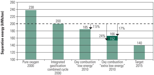 |
| 4. Reducing auxiliary loads. Compared with the state of the art in 2000, the energy needed for air separation has been progressively reduced. AL has improved the air separation unit (ASU) design to reduce its energy consumption. By optimizing the ASU for oxy-combustion conditions, this “low energy” ASU design produced a 7.5% reduction in power consumption: from the 200 kWh/ton baseline to185 kWh/ton. Further process and technology improvements (the “extra low energy” design) reduced separation energy a cumulative 17% from the baseline, to 166 kWh/ton. Adding heat integration into the plant steam cycle added another 7% improvement for a cumulative reduction of 24% below the baseline, to about 150 kWh/ton. AL is ready to demonstrate this design, and additional work is under way to achieve further reductions by 2015. In addition, the CPU is designed to achieve a low specific energy, on the order of 120 kWh/ton. Power reduction and the benefits of heat integration are major factors enabling the B&W/AL oxy-combustion design to achieve significant efficiency and cost advantages over other carbon capture technologies. Source: Babcock & Wilcox Power Generation Group and Air Liquide |
To maximize value, “peak-shaving” designs that employ liquid oxygen storage can be utilized. During peak load periods when the need for and price of electricity are high, the ASU can be shut down or run at low load, and liquid oxygen can be used to supplement operation of the plant. The ASU power would then be available for sale to the grid. In off-peak periods the ASU could run at full capacity, supplying oxygen to the combustion process while the remainder goes to storage.
Partial capture mode can be achieved by alternating between air and oxy-firing modes to obtain the desired CO2 capture rate.
Under oxy-firing conditions the CPU’s noncondensable vent is the only source of air emissions. As a result, the emissions from an oxy-combustion plant are stellar; there are essentially no particulate, mercury, heavy metal, HF, HCl, NOx or SOx emissions (see table). Only a small amount of NO, CO, and CO2 is emitted to the atmosphere.
 |
| Comparison of oxy-combustion air emissions to those from air firing and IGCC. Note that the oxy-combustion process will produce negligible emissions of common air pollutants. Source: Babcock & Wilcox Power Generation Group and Air Liquide |
B&W and AL have made significant advances in improving the efficiency and economics of oxy-combustion. Combining the advancements made by the two companies has resulted in improvements to plant efficiency and economics (Figures 5 and 6).
 |
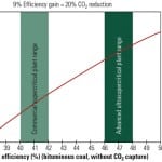
| 5. The best of many options. On an equivalent basis, oxy-combustion offers the best plant efficiency when compared with other CO2 capture options. For comparison, air-fired cases are the far left group, conventional carbon capture technologies are in the middle, and future carbon capture technology predictions are on the right. Data were taken from DOE/NETL 2007-1291 “Pulverized Coal Oxy-combustion Power Plants,” Rev. 2; DOE/NETL 2007-1281 “Cost and Baseline for Fossil Energy Plants,” Rev. 1; and B&W/AL Integration study using the warm recycle process with supercritical and ultra-supercritical steam conditions. Supercritical steam conditions are 3,500 psi, 1,110F/1,150F; ultrasupercritical conditions are 4,000 psi, 1,350F/1,400F. Source: Babcock & Wilcox Power Generation Group and Air Liquide |
 |
| 6. Attractive lifecycle economics. Note that the B&W/AL bars show the best improvements in the levelized cost of electricity when using oxy-combustion. All numbers are based on the same financial assumptions about burning the same bituminous coal and are estimated in 2007 dollars, not including owner’s costs. The notes in Figure 4 also apply to this figure. Source: Babcock & Wilcox Power Generation Group and Air Liquide |
In sum, the B&W/AL warm flue gas recycle design promises noticeably higher efficiency and improved economics compared with other carbon capture technologies when using DOE data. When ultrasupercritical boiler designs become available, the efficiency and economics of oxy-combustion will be comparable to those of today’s state-of-the-art air-fired supercritical power plants.
Oxy-Coal Demonstration Plant
Figure 7 illustrates all of the major components of the B&W/AL 150-MW gross (about 100 MWe net) oxy-coal demonstration plant design. The design uses the warm flue gas recycle process, in which the secondary recycled gas (shown with green flues) has only particulates removed, while the remainder of the flue gas (blue flues) has SOx, particulates, and moisture removed. The plant includes a regenerative air/gas heater with a special internal arrangement to eliminate oxygen loss and a unique direct contact cooler that removes and makes use of the water condensed from the flue gas. This top-level process diagram is similar to the one used for FutureGen 2.0, although the demonstration plant is smaller. Also, because FutureGen 2.0 burns a much higher sulfur coal, it uses wet flue gas desulfurization (FGD) instead of dry FGD, and the secondary recycle is taken after the scrubber (using the cool rather than the warm recycle process).
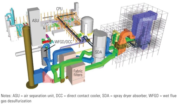 |
| 7. Unique plant arrangement. This design for a 150-MW gross demonstration plant illustrates similar components as will be used in the design of FutureGen 2.0. The major difference is that a wet FGD system will be used in lieu of the dry scrubber used for this demo plant. FutureGen 2.0 will also be slightly larger and will produce 200 MW gross. Source: Babcock & Wilcox Power Generation Group and Air Liquide |
Given that the demo plant was designed for only 150 MW gross, the steam cycle selected was subcritical at 2,400 psi and 1,050F main and reheat steam temperatures. Located in Wyoming, the plant employs dry condenser cooling that minimizes freshwater makeup. The plant was also designed for near-zero-liquid discharge.
Air emissions in the oxy mode come only from the CPU vent. NOx emissions are predicted at 13 tons/year or less (exclusive of start-ups). SOx, mercury, and particulates emissions in the oxy mode are projected to be below current power plant continuous monitoring accuracy. CO emissions without oxidation were projected to be about 780 tons/year. Approximately one million tons per year of CO2 would be captured and stored. About 105,445 tons/year would be released into the atmosphere, resulting in a capture rate of over 90%.
New Reference Plant Design
A reference plant design is useful to confirm the technical design basis and plant costs. Because the 150-MW gross plant just described was not selected by the DOE, the FutureGen 2.0 200-MWe gross plant will fulfill the need for a large-scale test facility.
The objective for FutureGen 2.0 is not only to apply the oxy-combustion technology at large scale but also to show that the plant can achieve 90%+ CO2 capture and confirm other emissions data. The project will also “confirm the cost basis for retrofitting/repowering existing coal-fired units,” and provide the information and experience that will reduce costs for future larger (500- to 800-MW-scale) units. For plant operators, FutureGen 2.0 will also “establish operating and maintenance experience for future commercial plants.”
FutureGen 2.0 is not the end game for the B&W/AL team. In fact, B&W, AL, and URS Washington Group in Denver have been working together to develop a utility-scale reference plant of 700 MW gross (about 515 MW net). The design is based on Powder River Basin coal using state-of-the-art supercritical boiler technology with turbine inlet conditions of 3,500 psi and 1,100F main and reheat steam temperatures. Originally sited at sea level in the Midwest, the plant was redesigned for a Kenosha, Wisconsin, location when the Electric Power Research Institute partnered with the project in mid-2010. Performance models and equipment sizing tasks are completed and estimates of plant costs are under development.
Preliminary results of the work predict that the net plant efficiency with carbon capture approaches the current coal-fired fleet average efficiency without CCS. Projections for air emissions in the oxy mode are very low: for NOx about 52 tons/year (not including start-ups); about the same CO as for a comparable air-fired plant (without oxidation); and SOx, Hg, and particulates below current power plant continuous monitoring accuracy. With 90% carbon capture, the plant would yield permanent storage of about 4.5 million tons of CO2 per year.
Two Oxy-Combustion Misconceptions
There are two significant misconceptions about oxy-combustion that should be laid to rest:
- The design of an oxy-combustion plant should use little or no flue gas recycling. Current full-recycle designs are immature, and future units will be able to operate with little or no flue gas recycling.
- Oxy-combustion is not a retrofit technology.
Low or No Recycle Is Impractical. Though a relatively small reduction in flue gas recycling may be practical for PC-fired boilers, the perception that low or no recycling is more advanced and that equipment sizes could be proportionately smaller and less expensive is not accurate.
To obtain similar gas mass flow in the furnace as with air firing, about 70% of the flue gas is recycled back to the boiler to control flame temperature, dilute corrosive constituents, and provide mass for convective heat transfer.
It has been proposed that with low or no recycling, a significant savings can be obtained. This misconception assumes that the cost of the equipment is closely related to the gas volume flow and that without recycling, oxy-combustion produces only 25% to 30% of the flow from an air-fired plant. First, reducing recycling has no impact on the cost of the ASU or the CPU. In addition, savings in the boiler island (boiler and downstream equipment) will be minimal or nonexistent, while performance and reliability risk will increase significantly.
Radiant and convective heat transfer in the boiler is balanced by the gas mass flow so steam temperatures can be achieved economically. Heat transfer to the water and steam contained in metal tubes is accomplished by radiation and convection. Furnace heat transfer is primarily by radiation from the flame. Beyond the flame, radiation begins to decrease, and as heat is absorbed into the tubes the gas temperature decays. The farther from the flame you get, the lower the radiation and the greater the convective heat transfer. The hotter the flame, the higher the heat fluxes in the furnace. To withstand these heat fluxes, water is used to cool the furnace tubes. Steam is about one-fifth as effective as water at cooling the tubes, so superheaters are generally located in the convection pass where heat fluxes are lower and practical, cost-effective materials can be used.
Furnace exit gas temperature control is also important for controlling slagging and fouling in the superheaters. Reducing recycle flow significantly increases flame temperature, burner zone heat release, and heat fluxes and also increases slagging concerns. With reduced recycling, furnace tube metal temperatures will be much higher, requiring higher alloys. Although higher gas temperature increases the log mean temperature difference, requiring less furnace heat transfer surface, the savings in material quantity is quickly overcome by the cost of higher alloy material, fabrication, and installation. Alloy material costs are often five or more times the cost of carbon steels. Even if furnace surface could be reduced by 50%, the material cost alone would almost triple, and the welding costs would be much higher due to pre- and post-weld heat treating requirements.
The lower gas flow has a similar impact on the convection surfaces, reducing the quantity but increasing the quality of the materials. Overall, reducing recycling even by 20% could reduce boiler weight by about that same amount while increasing material costs by as much as 30%.
Recent work has also shown that even using the latest materials, such as Inconel 740, it may be necessary to increase rather than decrease recycling to achieve supercritical steam temperatures of 1,300F or higher. Increasing recycling reduces furnace radiation and, more importantly, increases the flow available for convective heat transfer at more moderate heat fluxes.
For environmental equipment downstream of the boiler, cost savings are also lower than might be expected. These savings are not proportional to gas flow reduction for three reasons: the cost of these systems is not primarily in the vessels, flues, and casings; the performance and sizing of gas-cleaning systems is linked to the relationship between pollutant concentration and the gas volume flow, not the volume flow alone; and the perimeter is proportional to the square root of the volume reduction.
As recycling decreases, the same mass of pollutant is present, thus concentrations significantly increase. The increased concentrations challenge performance, and because the mass of pollutant is the same, most auxiliary systems—which represent most of the cost, such as ash removal and reagent preparation and handling—must have the same capacity and will cost about the same. Achieving performance goals becomes more difficult, ultimately limiting the practical size reduction of the equipment.
For example, in an electrostatic precipitator the same power is required for the same loading, sparking may tend to occur at a lower voltage, and the plate area is set by these factors, not by gas flow alone. In a fabric filter, higher loading (mass per volume of gas) requires a lower filtration velocity to maintain a practical back-pulsing frequency, which increases cost, and a practical gas-to-cloth ratio will set the volume of the filter.
When all factors are considered, any cost reduction in the equipment downstream of the boiler would likely be offset by increases in the boiler cost. In a typical oxy-combustion power plant, the boiler and downstream equipment represents about a third of the total plant cost. Design of an oxy-combustion pulverized coal plant with low or no recycling is questionably feasible using known materials, fabrication, and construction methods. Assuming that some small savings in the boiler island could be achieved, the net savings at the plant level would be diluted while significant performance and reliability risks would be introduced.
Oxy-Combustion Is a Retrofit Technology. Another criticism of oxy-combustion has been that it cannot be used as a retrofit technology. However, B&W/AL analysis finds that the added equipment needed for oxy-combustion requires about the same plant area and has about the same complexity of plant interfaces as post-combustion technologies. Oxy-combustion does not have the disadvantage of requiring major steam turbine modifications or the addition of an auxiliary boiler for energy supply to the post-combustion capture process.
Another advantage of oxy-combustion technology is that it can be installed to achieve partial CO2 capture now at a reduced capital cost, but it can be upgraded in the future for full capture with the addition of more ASU capacity.
A further advantage is that the oxy-combustion plant can be cycled; it can be operated in air-fired mode when electricity prices are high and in oxy-combustion mode when prices are low.
The B&W/AL analysis finds that oxy-combustion is just as practical to retrofit as post-combustion technology and appears to be more economical for 90% capture. The only advantage that a post-combustion process offers is the option to install a smaller plant to remove less CO2, but this has been shown to be more expensive per ton of CO2 removed than when installing a 90% capture system.
Final Thoughts
Oxy-combustion has come to the forefront of CCS options by projecting lower emissions and cost plus higher efficiency than other options. B&W and AL have invested significant effort in identifying and implementing improvements in components, systems, and process to achieve this potential. These efforts have produced the opportunity to build and test a commercial-scale 200-MWe gross plant with the DOE and Ameren through FutureGen 2.0. FutureGen 2.0 will be the largest scale CCS plant in the world and is expected to provide the basis for future CCS implementation.
While FutureGen 2.0 proceeds through Phase 1, B&W, AL, and URS are already working on the next step: a 700-MWe gross plant.
Oxy-combustion plants utilize proven commercial components promising high reliability. They operate very similarly to conventional PC-fired plants, making them more easily accepted by the utility industry. Operating schemes have also been developed to maximize revenue when power prices fluctuate drastically from day to night. Partial capture can be implemented if CO2 regulations start lower than 90% capture, and a plant can later be modified to achieve full capture as future emission limits are ratcheted downward.
— D.K. McDonald, PE (dkmcdonald@babcock.com) is technical fellow and Steve Moorman (samoorman@babcock.com) is business development manager, Advanced Technologies, for Babcock & Wilcox Power Generation Group Inc. Arthur Darde (arthur.darde@airliquide.com) is CO2 proposals manager and Sebastien de Limon (sebastien.delimon@airliquide.com) is deputy vice president of sales for Air Liquide Engineering & Construction Cryogenics Europe.