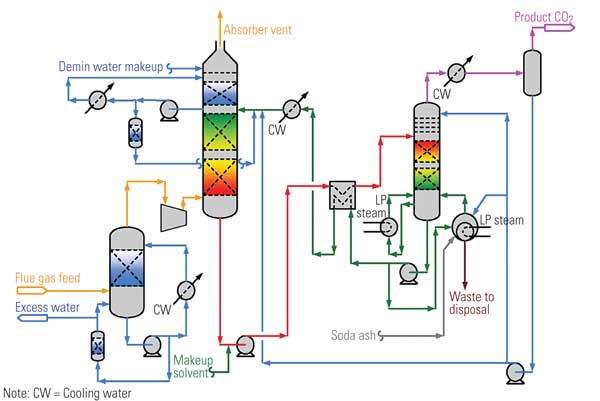
Clean Energy Systems Inc. (CES) has developed a zero-emissions power generation technology by integrating a component proven in the aerospace industry with conventional power plant equipment. Figure 1 is a simplified schematic of the CES process. Its most distinctive element (the third box from the left) is an oxy-combustor, similar to one used in rocket engines, that generates steam by burning a clean, gaseous fuel in the presence of gaseous oxygen and water. The clean fuel is prepared by processing a conventional fossil fuel such as coal-derived syngas, refinery residues, biomass or biodigester gas, or natural or landfill gas.
Combustion takes place at near-stoichiometric conditions to produce a mixture of steam and CO2 at high temperature and pressure. The steam conditions are suitable for driving a conventional or advanced steam turbine-generator, or a gas turbine modified to be driven by high-temperature steam or to do work as an expansion unit at intermediate pressures. After passing through the turbine(s), the steam/CO2 mixture is condensed, cooled, and separated into water and CO2. The CO2 can be sequestered and/or purified and sold for commercial use. Most of the water, which is purified separately, is recycled to the combustion chamber of the steam generator. Any excess can be sold.
Every component in the CES process, except for the oxy-fuel combustor, has been commercially proven in the power generation industry. Combustors similar to the one in Figure 1 have been a mainstay of rocket engines for decades. CES’s innovation has been to adapt them to power generation, in much the same way that aircraft jet engine prime movers were turned into aero-derivative gas turbine-generators.
1. Born from rockets, not jets. The core of the Clean Energy Systems zero-emissions technology process is an oxy-combustor (third box from left) that works much like the energy converter of a rocket engine. Source: Clean Energy Systems Inc.
Three rounds of initial funding
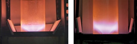
In 1999, the California Energy Commission (CEC) awarded CES an Energy Innovation Small Grant to help pay for the construction of a laboratory-scale oxy-combustor. With the money, CES built a test bench and a lab-scale combustor and operated the latter at temperatures up to 2,700F and pressures up to 300 psia. The combustor ran reliably and stably on O2, methane (CH4), and water for up to 48 minutes following more than 75 starts. The successful demonstrations provided the "proof of principle" for producing clean, high-energy drive gases suitable for generating electricity. The experimental work was completed in January 2001; for more details, see the final CEC program report at www.energy.ca.gov/pier/final_project_reports/CEC-500-2006-074.html.
In September 2000, the U.S. Department of Energy’s National Energy Technology Laboratory (NETL), under its Vision 21 program, began funding a CES effort to design, fabricate, and test a larger (20-MWt) combustor, fueled again by O2, CH4, and water. That unit (Figure 2) was tested during late 2002 and early 2003. The tests successfully demonstrated operation at temperatures ranging from as high as 3,000F to as low as 600F at pressures from 1,100 to 1,540 psia. The combustor operated successfully from 20% to 100% of its rated output during more than 95 tests.
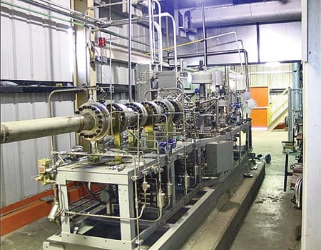
2. 20-MW marvel. The second oxy-combustor, funded by NETL, installed at the Kimberlina Power Plant. Courtesy: Clean Energy Systems Inc.
In early 2002, the CEC gave CES a much larger grant of $2 million to fabricate and demonstrate a natural gas–fired zero-emissions power plant based on CES’s oxy-combustor. The goals of this project were to evaluate the durability of the combustor and to identify desirable design refinements. In August 2003, CES acquired the idled, 5-MW Kimberlina biomass power plant near Bakersfield, Calif., from AES Corp. The CEC approved the use of this facility for the evaluation project in November 2003 and provided $2 million in supplemental funding in March 2004. After acquiring the Kimberlina plant, CES designed a complete control system for the 20-MWt combustor and integrated it into the unit.
Kimberlina is reborn
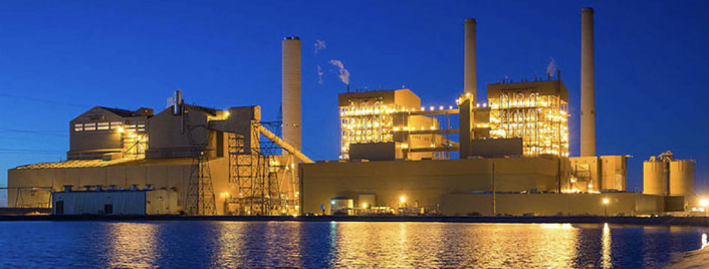
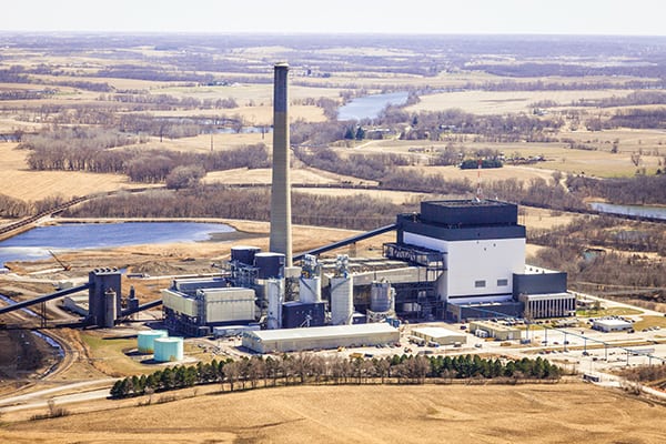
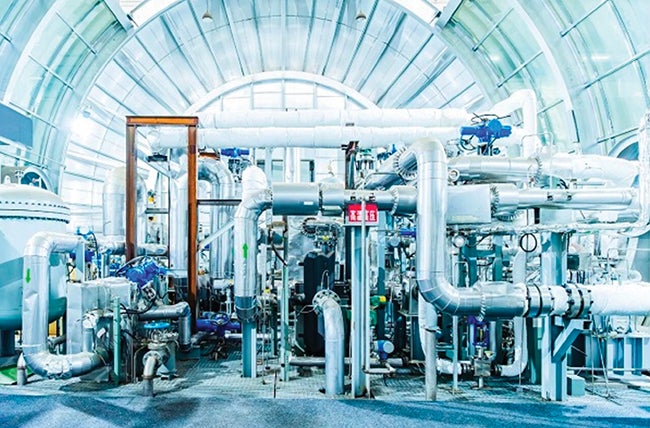
The Kimberlina facility (Figure 3) will provide the range of test and demonstration opportunities needed to facilitate commercialization of the CES technology and other oxy-fuel combustion systems. It is being developed in stages. Early on, Kimberlina served as a test facility for evaluating the durability and reliability of the oxy-combustor and to define the system design refinements called for by the CEC program (Figure 4). In the existing system, the turbine (Figure 5) is fed a mixture of 90% steam and 10% CO2. Its exhaust is routed to a geothermal-type condenser (Figure 6), which turns the steam to water and separates out the CO2.

3. Born again. CES purchased the idled Kimberlina biomass power plant and is using it to host an evaluation of its combustor’s durability. Courtesy: Clean Energy Systems Inc.
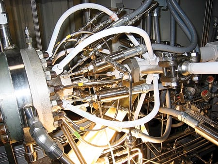
4. Maiden voyage. The combustor’s injection manifold is mounted on the 20-MW gas generator and fully connected to fuel, oxygen, and water piping on the test stand during the first operational run at Kimberlina. Courtesy: Clean Energy Systems Inc.
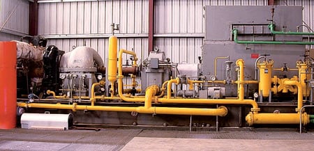
5. Alternatively fueled. The 5.7-MW gas generator/turbo-generator used at the Kimberlina test facility was built by Elliott Co. (www.elliott-turbo.com). The turbine is powered by a mixture of 90% steam and 10% CO2. Courtesy: Clean Energy Systems Inc.
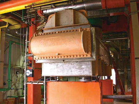
6. Binary by-product. The steam turbine exhaust goes into a condenser that separates it into water and CO2. Courtesy: Clean Energy Systems Inc.
The first equipment that CES installed at Kimberlina comprised an oxygen supply system, a natural gas compressor, a high-pressure feedwater pump, a new condenser, and a liquid-ring vacuum pump. To reduce program costs, the processes of recovering CO2 and purifying it to a level suitable for commercial use were excluded from the scope of the CEC project. However, future activities at Kimberlina may include pilot testing of CO2 sequestration via injection into saline aquifers and/or CO2 flooding of nearby oil fields to enhance oil or gas recovery from them.
In late 2004, validation testing and commissioning of the integrated combustor/control system and its associated feed systems were completed using natural gas as the fuel. In December 2004, engineers diverted some of the drive gas from the oxy-combustor to the 5.7-MWe turbo-generator, partially bypassed to the stack, and brought the turbo-generator to synchronous speed. In February 2005, Kimberlina was synchronized to the local grid for the first time. One month later, the plant was operated in pure "power island" mode, disconnected from the grid. Shortly thereafter, permission to connect to the grid was granted and power began flowing from the plant.
Excellent early results
Between March 2005 and March 2006, CES conducted the durability and performance tests that the CEC program mandated. During this period, the combustor was started more than 300 times and accumulated 1,500 hours of operation. Individual test runs ranged in duration from less than 1 minute to about 105 hours. The plant’s output was varied from 20% to 88% of its full rating. Power was exported to the grid at levels from 0.5 MW to 2.7 MW during 141 runs encompassing 1,243 hours of combustor operation. The combustor operated continuously for longer than 8 hours during 43 of these runs, and for longer than 24 hours during 11 runs. During the tests, the plant was fueled with natural gas, simulated syngas, and liquid fuels containing sulfur.
At 50% power, measured CO emissions ranged from 0.02 to 0.31 lb/mmBtu over a wide range of gas generator system operating conditions. (For comparison purposes, a typical gas turbine’s CO emissions range from 5 to 80 ppmv, corrected to 15% O2.) CO emissions tended to increase when the gas generator was operated at higher power levels. At 50% power, measured NOx emissions ranged from 0.003 to 0.019 lb/mmBtu, corrected to 15% O2.
These measured CO and NOx emissions levels are considerably lower than those of state-of-the-art combined-cycle power plants fueled by natural gas and using selective catalytic reduction for NOx control. CES has developed strategies for further lowering emissions of CO and NOx from the first-generation gas generator and will experimentally evaluate them in future testing efforts. Unburned hydrocarbon emissions for two different operating stoichiometries were 0.9 ppmv and 1.8 ppmv, corrected to 15% O2. These emissions are only of interest if the noncondensible gases are vented to the atmosphere, but in most commercial installations, these emissions would be sequestered with the carbon dioxide.
In March 2006, the CEC notified CES that the program objectives had been met and that no further testing was required by the project. Around this time, representatives of two major insurers of power plant equipment toured the Kimberlina plant and reviewed the combustor’s operating records (the number of starts, operating hours, shutdown circumstances, maintenance experience, and inspection findings). Following their inspection and review, the insurers declared that the combustor is insurable, and coverage is now in place. CES considers the insurability of the combustor essential to its commercial deployment.
With the conclusion of the CEC-sponsored durability evaluation, CES began configuring the Kimberlina facility for testing the performance and reliability of the oxy-combustor when burning lower-cost, lower-Btu fuels such as coal-derived syngas.
Evaluating fuel diversity
In September 2005, NETL awarded CES $4.5 million to evaluate and develop a coal-based oxy-syngas combustor suitable for a high-efficiency, zero-emissions power plant. Under the same DOE program, Siemens Power Generation received a $14.5 million award to develop high-temperature turbines compatible with the CES combustor. These turbines would be capable of operating at up to 3,200F when fueled by steam/CO2 drive gas.
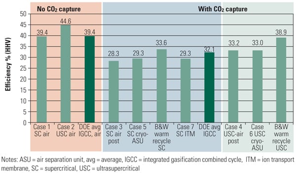
The three-year CES project will be executed in three phases. In Phase I, CES and Nexant Inc. conducted process modeling to evaluate CES power plant concepts that have the potential to produce power from coal at net cycle efficiencies of >40% (HHV), with CO2 capture by 2015. The models incorporate all major process components depicted in Figure 1, including the combustor, turbines, gasifier, the air separation plant, heat exchangers, and CO2 conditioning unit. The information required to model these components was solicited from Siemens, ConocoPhillips, Air Products and Chemicals Inc., G.C. Broach Co., and Kinder Morgan Inc. CES and its partners modeled and evaluated the potential benefits of integrating subsystems into the overall system to maximize overall plant efficiency and electricity production cost.
CES and Nexant will also investigate power/hydrogen co-production plants. At such plants, hydrogen will be separated from the coal-derived syngas and marketed as a by-product, leaving hydrogen-depleted syngas (HDS) as the fuel for the CES oxy-combustor. This option may be particularly attractive if the objective is to produce hydrogen for off-site use (such as to power fuel cells) while providing a fuel source other than high-value hydrogen for on-site power generation. Although further analysis is required and will be conducted under the aegis of the NETL project, the CES process appears eminently suitable for fueling by HDS.
In conjunction with the Phase I modeling effort, CES operated the existing Kimberlina combustor on simulated coal syngas and HDS. In these tests, a gas blending station was installed at Kimberlina and used to supply the combustor with both fuels. Specifically, the blending station delivered mixtures of CO, H2, CO2, N2, and CH4 to the combustor, which was modified to accommodate the lower-heating-value fuel. Although the tests were limited to firing rates of 5 MWt or less, they enabled CES to assess the performance and combustion/emissions characteristics of the oxy-combustor on coal-derived fuels. Following the tests, CES is exploring options for testing the Kimberlina combustor at a gasification facility, to demonstrate its compatibility with actual coal-derived syngas.
In Phase II of the project, which is currently under way, CES will use data from the 5-MWt tests to design a 50-MWt (nominal) combustor optimized for operation on coal syngas and HDS. In this effort, CES will use its experience and expertise to scale up Kimberlina’s existing, 20-MWt natural gas combustor. In Phase III, CES will fabricate the combustor and install and test it either at Kimberlina or at another location.
Commercialization: The final step
With the successful conclusion of the CEC program, sufficient experience and confidence has been gained to justify contracts for modest-sized (20 to 70 MWe) first-generation plants using present-day steam turbine technology. These projects fall into two categories: natural gas–fueled plants located where government incentives or CO2 credits are available, and coal or coke-fueled plants whose CO2 and (possibly) hydrogen outputs could be marketed separately or bundled with ultra-low-emissions power. Two existing projects in the first category are described below.
The SEQ-1 Project in the Netherlands will use a modified CES process. A CES combustor operating at modest pressure (~500 psia) and fueled by natural gas recovered from a "depleted" field will create steam in a compact heat-recovery steam generator (HRSG) that will drive conventional steam turbines. This 50-MWe (nominal) power plant will pump the captured and separated CO2 into the same field to enhance gas recovery.
Three unique factors favor the commercial viability of this project:
- The Dutch government has legislation in place that subsidizes climate-neutral electricity sources (including zero-emissions power plants) to the same extent as wind, solar, and biomass power.
- The geology of the gas field has been determined suitable for enhanced gas recovery.
- Dutch developers, working with CES, have brought together the necessary entities to evaluate the project and reach a consensus about its viability. A consortium to develop the project has been formed; among its members are ONS, a Dutch municipal utility, and a major European oil and gas company.
For more information on this project, visit www.seqnederland.nl.
The Zero Emissions Norwegian Gas (ZENG) Project is being jointly developed by Lyse Energi AS, Nebb Engineering AS, Procom Venture AS, and CO2-Norway. It is supported by Norway’s Oil and Energy Department, Lyse Energi, and the U.S. DOE. The goal of this program is to develop and demonstrate "near-commercial" technology for zero-emissions power generation using Norwegian natural gas to fuel CES’s oxy-combustor. Zero-emissions power plants are of particular interest in Norway because its government imposes high taxes on CO2 emissions.
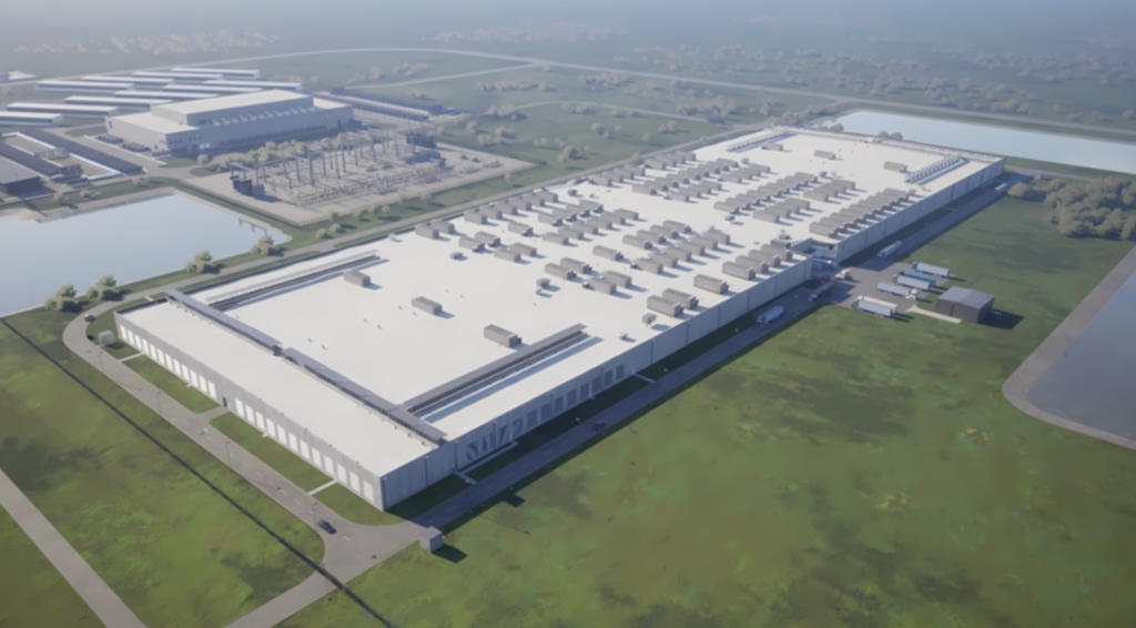
The ZENG project (Figure 7) is a multiphase effort. Phase 1, completed in July 2004, produced a concept and feasibility study. Phase 2, completed in late 2005, focused on preengineering and qualification. Subsequent phases will entail construction of a 50-MWe demonstration power plant near Stavanger, Norway, that could be commissioned as soon as 2009. Later, a high-efficiency, 200-MWe zero-emissions power plant would be built at a Norwegian location to be determined. For more information on this project, visit www.zeng.no.
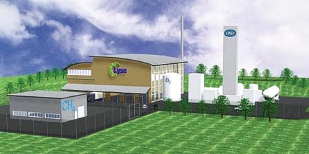
7. Carbon tax shelter. An artist’s rendering of the 50-MW zero-emissions demonstration plant to be built as part of Norway’s ZENG project. Source: Clean Energy Systems Inc.
CES will also work to make the oxy-combustor compatible with solid fuels. It expects the first generation of plants of this type to have a capacity of about 70 MWe. At their front end will be gasifiers able to turn low-cost coal or coke feedstock into syngas fuel for the CES combustor. These plants will use the indirect cycle proposed for the SEQ-1 project: the combustor’s output raises steam in a compact HRSG that is used to drive conventional steam turbines. Early plants will use several of the 50-MWt syngas combustors that were demonstrated successfully at the Kimberlina facility. Later plants will leverage lessons to be learned about the combustor and controlling it as part of the SEQ-1 project.
Ideally, a solid-fueled oxy-combustor plant would be sited where there is a local use for the CO2 by-product (enhanced oil or gas recovery, for example) and where air-quality rules are particularly stringent. An optional feature of the CES process involves separating hydrogen from the syngas stream and using the remaining HDS to fuel the combustor. In these cases, the separated (and very valuable) hydrogen by-product stream could be delivered to local users such as refineries or heavy-fuel upgraders, or injected into a hydrogen pipeline.
Watch out, IGCC
In January 2007, CES announced that it is seeking funding to build the nation’s first natural gas–fueled zero-emissions power plant, a 50-MW facility to be sited in California. So far, Southern California Gas Co. has committed to support development of the technology. CES is also seeking funding for the proposed plant from the U.S. DOE and the CEC.
This project, and the ones described earlier, will set the stage for second-generation plants that will use intermediate-pressure gas turbines and other technologies to enable higher-efficiency, low-cost power generation from coal—with CO2 capture. Near-term plants (available in about five years) would modify existing turbines and other components. Longer-term plants (available in about 10 years) would use advanced technologies such as the high-temperature turbines being developed by Siemens Power Generation with its September 2005 NETL grant.
The second-generation plants would exploit future advances in air separation as well as synergies among the air separation unit, the gasifier, and the power island. By virtue of their high cycle efficiencies and low electricity production costs, oxy-combustor plants look to be a serious cost competitor to other methods of converting coal to electricity with CO2 capture—most notably, integrated gasification combined-cycle (IGCC) plants.
—Keith Pronske is president & CEO of Clean Energy Systems Inc. He can be reached at klpronske@cleanenergysystems.com
.