Most plant staff members periodically take a CPR course as part of their ongoing qualification program. It’s a short and simple class that folks may take for granted after repeating it so many times. You may never use the skill, but when you do, your response must be nearly automatic. So here’s a pop quiz: What’s the first step in performing CPR? Know your ABCs: Check the airway and then breathing and circulation. The mnemonic is easy to remember and can save a life.
A similar simple but effective approach can be used to assess the performance of a coal-fired steam generator. Manage the airflow first and then the fuel flow to obtain the best combustion results possible given the constraints of the boiler design. Hopefully, the results will be similar to those achieved with CPR: a long and productive life.
Later in this article we present a case study for a typical 500-MW pulverized coal (PC) boiler and apply a set of best practices to measure, balance, and control furnace inputs to achieve higher combustion efficiencies and lower NOx emissions. When you see the results, you may decide that CPR stands for "coal plant revived."
Get the airflow right
Ideal pulverized coal combustion occurs when a coal particle is burned completely and all of the carbon is converted to CO2, all H2 is converted to H2O, and all sulfur is converted to SO2. Deviations from ideal combustion are indicated by higher-than-desired carbon in ash, secondary combustion at the superheater, and objectionable CO levels in the flue gas. Most large utility boilers were originally designed to operate with 15% to 20% excess air (Figure 1) to make up for air and fuel imbalances in the burner belt. Critical tolerances for the combustion airflow paths to the boiler are noted in Figure 2.

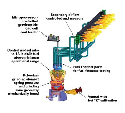
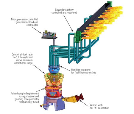
1. Different paths. Air commonly takes three different paths, but it all ends up in the furnace—whether you want it there or not. The key to achieving excellent combustion efficiency is properly managing the amount of air supply and plugging the leaks. Source: Storm Technologies
2. Short course. These are the key design and operating measures for combustion air, from the pulverizer to the furnace, for a typical 500-MW coal-fired plant. Source: Storm Technologies
Within most utility furnaces, the residence time for coal particles to completely burn out is only between 1 and 2 seconds (Figure 3). Boilers designed in the 1970s had pre-low-NOx burners, and the short furnace residence time was compensated for by intense and turbulent mixing, with a very high flame temperature. The intensity of burner belt combustion, with the resultant high NOx production, is unacceptable today. Today’s typical low-NOx burners have evolved into systems that inject combustion air into two, three, or four air zones at the burners (secondary air). For further reduction, most low-NOx firing systems utilize multiple levels of combustion airflow for staged combustion. A best practice is to ensure that combustion is completed in the furnace with a stoichiometry of 1.15 to 1.20 (excess air of 15% to 20%) before the products of combustion reach the superheater.

3. Burning desire. Best practices dictate staged combustion with multiple air zones in the furnace to manage NOx production. Many boilers have relatively short furnace boxes with residence times below the desired 1 to 2 seconds. Source: Storm Technologies
You may remember how automotive emissions were significantly reduced by adopting electronic fuel injection systems to precisely regulate the amount of air and fuel reaching each cylinder. Later, combustion chamber designs were altered to stage and slow down combustion. That reduced peak combustion temperatures and thereby lowered the rate of NOx formation. Consumers observed reduced emissions but also a significant improvement in automobile performance. Today, a computer can control individual piezoelectric injectors to create five or more injections per cycle in modern diesel engines to optimize performance and emissions under any conceivable operating condition. And it all started with applying combustion fundamentals to the internal combustion engine and leveraging IT advancements for more precise control and data collection.
The principle also holds with power plant combustion fundamentals. Today’s coal-fired boilers continue to make similar progress with parallel commercialization of low-NOx burner technology, control systems, smart closed-loop systems, and neural networks. Improvements in pulverized coal combustion with solid fuel injection systems are in our future; they closely parallel the product development trajectory that resulted in advanced performance and emission controls for automotive internal combustion engines.
The solid fuel injection system approach for a natural gas–like rapid response to load changes can be mimicked by improving airflow measurement and control.
Primary airflow in a PC-fired boiler is akin to the gas valve of a gas-fired boiler. Achieving rapid response of pulverized coal to the furnace requires accurate and responsive changes in the transport or primary airflow. In-furnace NOx reduction by staged combustion or "lean burn" is possible by using measured and controlled overfire airflows. This can be effective when pulverizers are optimized for the best fineness and distribution as a complement to the optimum proportioning of total air and fuel delivered to the furnace.
The question is, How do we get there from here?
Back to the fundamentals
Although most of the general principles used in the power industry today are correct, the fundamentals are rarely appreciated. A 1- to 2-second residence time in the furnace for the entire combustion process doesn’t leave much time for the air and fuel to migrate from fuel-rich and air-rich zones, mix to achieve optimum theoretical air and fuel ratios, and completely combust. Some furnaces are even equipped with water-cooled platens for enhanced heat transfer. But these may actually be counterproductive because they inhibit the left-to-right mixing of fuel-rich and air-rich products of combustion, even if there is sufficient residence time (Figure 4).

4. Time in stir. This chart shows how the typical coal particle spends its residence time in a coal-fired boiler. Smaller particles (better fineness) increase the amount of carbon changed to CO2 and decrease the amount remaining in flyash leaving the boiler. Source: Storm Technologies
Low-NOx burners purposely and deliberately stage combustion for a slower burn with a flame of reduced intensity. The reduced-intensity flame has a lower temperature, generates less NOx, and releases less fuel-bound nitrogen. Staged combustion may reduce flame intensity, but it causes increased flame lengths. Burners designed in the 1970s or earlier were developed for high-intensity and closely spaced burners with high heat release—typically between 150 and 200 mmBtu input. They produced a flame length of between 15 and 20 feet. A similar sized low-NOx burner with lower flame intensity and internally staged combustion may have a flame length of 50 to 60 feet (or more if operating below a stoichiometry of 1.0). The inevitable flame impingement on superheater and other radiant and convection tubes will drive up O&M costs as a result of tube replacement or will reduce plant availability when tube leaks are repaired.
Active combustion in the superheater also contributes to increased slagging, fouling, hot tube metal temperatures, high desuperheating spray water flows, and the production of "popcorn ash" cinders that contribute to selective catalytic reduction system and air preheater fouling. The resulting carryover of flames into the superheater usually results in one of two conditions:
- Flame quenching below the temperature at which carbon combusts, which results in higher carbon in ash than desired.
- Extremely high flue gas temperatures that result from secondary or continued combustion in the superheater.
Fuel balancing and the optimization of coal and air from the pulverizers are essential. The compartmentalized windbox on a utility boiler is superior to an open "plenum" windbox, as it can closely proportion the combustion airflow—and fuel flow—from each pulverizer, assuming the flow-measurement devices and control dampers are optimized. However, with longer diffused and less-intense flames that require longer residence time, fuel and air imbalances and secondary combustion results are exacerbated. The fuel-rich portions of the flames will extinguish themselves when the oxygen is depleted. And with fuel line imbalances, the burners and regions of high flame temperatures create very high NOx levels by the combination of nitrogen in air, thereby inducing greater thermal NOx.
Furthermore, the combustion process is complicated by fuel and air imbalances that often range up to and beyond 20%. For example, take a burner operating at +10% fuel and –10% secondary air. The stoichiometry with an average of 20% excess air would be 1.0. That is precisely the proper amount of oxygen to burn all carbon to CO2 and all H2 to H2O. The other burners might have low fuel and high air in the neighborhood of +40% excess air, which will result in a lean, hot burner zone that produces very high NOx. Often overlooked is the fact that boilers are designed for zero air in-leakage from the furnace to the economizer outlet flue gas. More on this in a moment.
Restore balance
The preferred approach to combustion optimization, in our experience, is to measure and control all of the furnace inputs of air and fuel to achieve the original design proportions of fuel and combustion air reaching the furnace. This means that getting the inputs right is the first step. Controlling NOx and SOx with postcombustion solutions is the second.
Complicating the operation of a solid fuel system are the furnace exit slagging and fouling considerations. Not only must combustion be optimized for minimum NOx, but combustion must also be completed before furnace exit gases enter the superheater.
Case in point
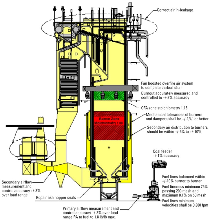
A case study on improving combustion efficiency and emissions on a typical 500-MW wall-fired boiler will clearly illustrate these points (Figure 5).
5. Learn from others. Air in-leakage into a typical balanced-draft 500-MW coal-fired boiler can seriously reduce plant thermal efficiency and negatively impact furnace O&M. This plant is operating at full load operating with 15% excess air with no air in-leakage. Source: Storm Technologies
There are many varieties of approaches to combustion airflow measurement and control. In our experience the most reliable and accurate methods use a venturi or flow nozzle to measure airflow. Many believe that these devices cannot be installed in the close-coupled ductwork of airflow entering a coal pulverizer or around the bends of ductwork in an overfire air system. Not true. We routinely use either a venturi, a flow nozzle, or both. However, they must be properly installed and field calibrated using hand velocity traverses. Because of the vastly different densities of cold air and operating temperature airflows, we strongly recommend the "Hot-K" calibration and measurement verification of airflows under actual operating conditions. Surface-measured static pressures at the high-pressure and low-pressure sensing taps are affected by the boundary airflow over the internal duct surfaces and are therefore influenced by surface discontinuities.
For example, placing a venturi immediately after a primary air fan has always been problematic. But we have successfully added the venturi many times using our calibration section of the venturi throat and using the "Hot-K" calibration method (Figure 6). Another difficult application is on an exhauster-equipped pulverizer such as deep bowl, Raymond bowl mills. The ductwork arrangement shown in Figure 7 is typical of our approach to primary airflow measurement on pulverizers operating under suction pressure.
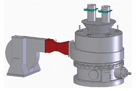
6. Squeeze job. A high-accuracy venturi can be placed between a close-coupled fan and a pulverizer. Source: Storm Technologies

7. Drawing a vacuum. A similar configuration with a venturi is possible on pulverizer ductwork that’s typically under negative pressure. Source: Storm Technologies
Commonly used averaging pitot tube arrays, with straightening vanes such as those shown in Figure 8, have functioned satisfactorily in clean air. However, when regenerative air heaters are used, as is common on large PC boilers, a certain amount of the flyash is recirculated as the air heater rotates, resulting in honeycomb pluggage (Figure 8). Plugging is another reason to conduct periodic inspections and to implement a program of periodic airflow calibrations using the "Hot-K" method.
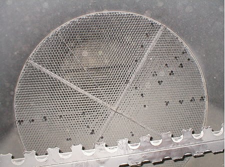
8. Straight and narrow. A "honeycomb" flow-straightener was partially plugged by flyash recirculated by the regenerative air heater. Courtesy: Storm Technologies
The obvious reasons to accurately measure airflows to the furnace are to ensure that inputs to the burner belt are correct and to establish those airflows as the baseline for future testing. Often we find there is simply insufficient furnace combustion airflow to complete combustion. Because the average large utility boiler is more than 30 years old, it should not be a surprise that many units not getting a good breath of air are of the balanced-draft design and have significant "tramp air" in-leakage. Air leaks not only contribute to a heat rate penalty, but they also contribute to poor furnace performance, slagging, fouling, and higher-than-optimum carbon-in-ash content.
Worse yet, air in-leakage goes undetected by normal plant instrumentation. That is, excess oxygen measured at the economizer outlet is "assumed" to have entered the furnace through the burners or overfire air ports. In fact, sometimes as much as 20% of the total air thought to have entered the furnace actually entered the boiler convection pass via what should be the postcombustion flow path of the products of combustion.
9. Air leaks reduce efficiency. Actual excess air as a function of casing leakage. The data points are based on a 3% O2 setpoint with 20% overfire air. Source: Storm Technologies
10. Inaccurate measurements. A correlation of "true" in-furnace oxygen versus the assumed oxygen levels measured at the O2 probes with varying levels of leakage upstream of the O2 probes. Source: Storm Technologies
Plugging air leaks
Now that we have gone through the calculations, let’s review why air in-leakage can really siphon points off a plant’s heat rate, performance, and unit reliability. As you can see in Figures 9 and 10, excess air entering the furnace or convection path has a large impact on "true" excess air. Data for these figures were taken upstream of the air heater and prior to the excess O2 probes.
A mere 7% air infiltration upstream of the excess O2 probes with accepted air and fuel imbalances correlates with a burner stoichiometry of about 0.85, or 15% excess air required to complete combustion (Figure 9). When fuel or airflow is imbalanced more than 10% and/or overfire air is deep staged to +20% for NOx control, stoichiometry will be even lower. Units retrofitting flue gas desulfurization systems and/or firing high-sulfur coals understand that sulfur and chlorine are harmful corrosion compounds and accelerate water wall corrosion in a reducing atmosphere.
Users should consider periodic water-cooled high-velocity thermocouple probe measurements of furnace exit flue gas excess oxygen. Total airflow measurements of primary airflow, secondary airflow, and overfire duct airflows should also be periodically verified for calibration. Calibrations should be completed to complement acceptable mill performance testing that ensures desirable air-fuel ratios and acceptable coal fineness.
Another problem: Today’s low-NOx burners with multiple stages of overfire air and flame-attachment burners are designed to create fuel-rich flame cores and result in less NOx production. Often, burners of scientifically proven good designs self-destruct due to overheating and metal deformation. Seldom is this destruction due to the burner design itself.
Our experience has been that burner reliability and NOx reduction performance are largely related to the fuel balance, combustion airflow balance, accuracy of flow indications, residence time (some furnaces have more time by design than others), air in-leakage, burner line pluggage, burner type, and primary airflow velocities—among a number of other factors.
Some original equipment manufacturers of burners utilize underfire air, curtain air, side wall air, and/or multiple overfire air injection ports throughout the boiler. Sometimes these ports are designed for good scientific reasons. However, most of the time they are used as a back-up source for NOx reduction to reduce the burner belt flame intensity and stoichiometry while delivering uncontrolled and unmeasured airflow. By introducing unmeasured, uncontrolled airflow, precision in measuring and control of the stoichiometry is lost.
We also routinely observe that imprecise measurement and control of combustion airflow, coupled with problematic pulverizers, is the root cause of localized reducing atmospheres in the burner belt zone. All too often the result is aggressive fireside tube wastage, especially with higher–iron content and higher-sulfur bituminous coals.
—R.F. (Dick) Storm (rfstormsea@aol.com) is president of Storm Technologies (www.stormeng.com). Stephen K. Storm (skstorm1@aol.com) is a vice president of the company and its manager of technical field services. Stephen G. Hall (stephen.hall@stormeng.com) is a field service engineer for Storm Technologies.