Turbophase enables combustion turbine owners and power grids to increase flexibility, power, and efficiency, which is critical at a time when dispatch of renewable energy is growing. Combustion turbines, particularly aero-derivatives, are increasingly required to be “renewable ready.”
Most visions of power generation in the future include the following: more renewables, more decentralization, and more combustion turbines (CTs) increasingly powered by natural gas. It’s projected that more than $1 trillion of new electric power generation will be built by 2035, and a large and growing share will come from natural gas power CTs and renewables.
Three key trends are driving the greener energy future: pressure on coal and nuclear driven by consumer demand and government regulation; accelerating renewable energy deployment driven by rapidly falling costs, particularly of solar panels; and synergies between renewables and CTs, specifically the intermittent nature of renewables coupled with the dispatchable, flexible nature of CTs.
Of all CTs, aero-derivatives are typically the most flexible and decentralized, making them uniquely suited for this new paradigm.
Turbophase Benefits on an Aero-derivative Combustion Turbine
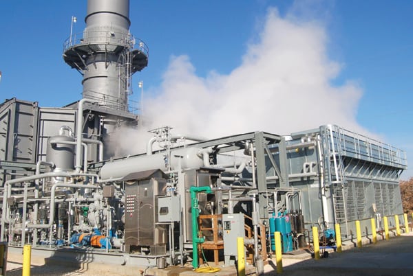
Turbophase (Figure 1) is a CT optimization system that utilizes a high-speed reciprocating engine to drive a multi-stage intercooled centrifugal compressor. It then uses the engine exhaust energy to heat the compressed air, resulting in dry, hot compressed air that is then injected into the CT.
 |
| 1. The Turbophase system. The Turbophase module, shown here in a rendering with its sound enclosure faded, uses a high-speed reciprocating engine to drive a multi-stage intercooled centrifugal compressor, then uses engine exhaust energy to heat the compressed air, resulting in dry, hot compressed air that is injected into the combustion turbine (CT). Courtesy: Powerphase |
Adding Turbophase to the CT enables the CT to generate optimal performance in both output and fuel efficiency in all ambient conditions regardless of ambient temperature, relative humidity, and altitude. By applying Turbophase to a simple cycle aero-derivative CT, the CT gets an additional 20% output when needed, delivered immediately when called, and the CT operates at 5% better fuel efficiency. In a world of high renewable penetration with a premium on green energy, this fast response, improved efficiency aero-derivative CT is very desirable.
It’s a commonly known fact that all CTs lose power as ambient temperatures rise, which is typically when power is needed most. The reason CTs lose power is that as ambient temperature or elevation increases, the density of the air decreases naturally, reducing the mass flow into the CT. The reduced mass flow results in decreased fuel flow to hold turbine inlet temperatures constant, with the ultimate result being less output.
Turbophase restores the mass flow that is naturally missing by injecting air into the compressor discharge. The CT control system reacts automatically and increases fuel to account for the increased air mass flow, resulting in constant turbine inlet temperature. The increased mass flow (Figure 2) through the turbine section increases the mechanical torque to the compressor and generator.
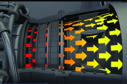 |
| 2. Increased mass flow. Turbophase restores mass flow that is naturally missing by injecting air into the compressor discharge. The CT control system reacts automatically and increases fuel to account for the increased air mass flow, and the higher flow through the turbine increases mechanical torque to the compressor and generator. Courtesy: Powerphase |
Aero-derivative CT: Technical Details
Powerphase recently signed a partnership agreement with Pratt & Whitney Power Systems (PWPS) to offer its Turbophase products to PWPS CT owners, specifically the Aeroderivative FT8. This will give FT8 owners the flexibility to increase CT power, efficiency, and/or durability based on site (Figure 3) and market requirements.
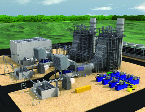 |
| 3. An installation of eight Turbophase modules. This is a 3-D rendering of a combined cycle gas turbine (CCGT) plant with eight Turbophase modules installed, thanks to abundant space at the site allowing the operator to add units to increase power and efficiency. Courtesy: Powerphase |
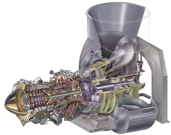
The Turbophase compressor is designed to support the higher-pressure ratio aero-derivative turbines with either a 4-stage compressor up to 270 psi CT compressor discharge pressure, or a 5-stage compressor with greater than 270 psi CT compressor discharge pressure (Figure 4).
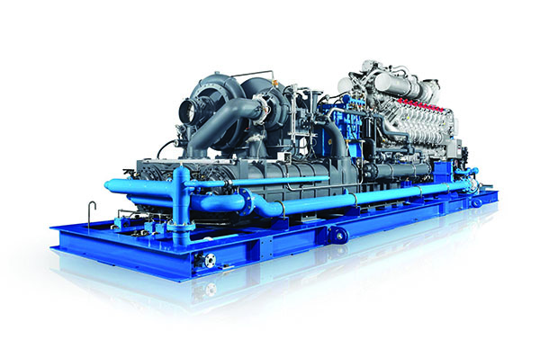 |
| 4. Turbophase module with multi-stage compressor. This Turbophase module has a multi-stage compressor and reciprocating engine. The unit is shown absent its sound enclosure. Courtesy: Powerphase |
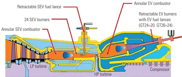
The FT8 CT is derived from a Pratt & Whitney JT8D engine. The high-pressure (HP) shaft connects the 7-stage HP compressor and a single-stage HP turbine, and the low-pressure (LP) shaft connects the 8-stage LP compressor (LPC) and 2-stage LP turbine. A 3-stage free power turbine drives the electric generator (or mechanical drive). The combustor chamber has nine cans arranged around the turbine circumference, terminating in an annular transition section leading to the HP turbine. The two-spool HP and LP turbine sections are also known as the “gas generator.”
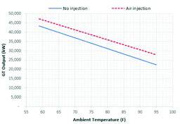
Figure 5 shows CT power as a function of temperature. Results have been obtained through cycle calculations carried out in GTPro/GTMaster and SOAPP software based on a “generic” FT8-3 CT in simple cycle. Air density is higher at lower temperatures, and as a consequence the mass flow through the turbine is higher, resulting in more power. CT performance was simulated with 5% air injection of the base case. Average incremental output is ~2.7 MW across the temperature range. Non-injection cases are shown as triangular blue markers in the figure. Injection cases are shown as circular red markers in the figure.
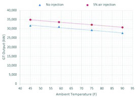 |
| 5. Output at varied ambient temperatures. This graphic shows how turbine power output changes at various ambient temperatures. Performance of an FT8-3 turbine was simulated with 5% air injection of the base case, and without 5% air injection. Average incremental output is ~2.7 MW across the temperature range. Non-injection cases are shown as triangular blue markers in the figure. Injection cases are shown as circular red markers in the figure. Courtesy: Powerphase |
Normally, FT8 CTs used in power generation are provided in a SWIFTPAC configuration where two CTs are connected to a single generator. Therefore, the actual power output for a SWIFTPAC is >60 MW at ISO conditions. In that application, the nominal Turbophase air injection flow for one module is equal to providing 5% air injection to each CT, resulting in more than 5.4 MW of incremental power per Turbophase module per SWIFTPAC.
The air injection manifold is connected to the 13th stage bleed port at the discharge of the HP compressor (Figure 6). Injection air is mixed with compressor discharge air, flows to the combustion cans, and then is expanded through the HP, LP, and power turbines.
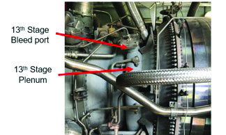 |
| 6. Location, location, location. The air injection manifold is connected to the 13th stage bleed port at the discharge of the high-pressure compressor. Injection air is mixed with compressor discharge air, flows to the combustion cans, and then is expanded through the high-pressure, low-pressure, and power turbines. Courtesy: Powerphase |
Turbophase on an LM6000
The LM6000 is a two-shaft CT derived from the CF6 engine. It has a nominal output of 42.5 MW and a heat rate of 8,350 Btu/kWh (LHV, lower heating value). The HP shaft connects the 14-stage HP compressor and 2-stage HP turbine, and the LP shaft connects the 5-stage LPC, 5-stage LP turbine, and electric generator. Engines use either a single annular combustor (SAC) or a dry low emissions (DLE) combustor.
The air injection manifold is connected to the compressor discharge customer bleed ports at the compressor rear frame. In SAC CTs, injection air is distributed via struts 2-4 to the internal diameter of the combustor section, downstream of the compressor discharge plenum. In CTs equipped with DLE combustors, injection air is distributed via struts 2-3. Injection air is evenly distributed with compressor discharge air, and then flows to the combustion chamber (either SAC or DLE), and then is expanded through the HP and LP turbines.
Figure 7 shows simulation results for CT power as a function of temperature for the LM6000 engine without spray intercooling (SPRINT), in which a fine mist of water is injected at the compressor reducing the temperature and acting as an intercooler. Incremental output for the same amount of air injection varies between 4 MW and 5.6 MW across the temperature range. At a higher ambient temperature, the mixing effect of the injection air and the compressor discharge air allows for a reduction in compressor discharge temperature (T3). Consequently, the HP-shaft speed can be increased and there is an added benefit of increased air flow due to the higher shaft speed. This explains why the incremental power with air injection is higher at higher ambient temperatures. Similarly, air injection can result in heat rate improvements above 7% at high ambient temperatures.
 |
| 7. LM6000 output at various ambient temperatures. This graphic shows how the power output of an LM6000 turbine without spray intercooling changes as ambient temperatures change, at levels both with and without 5% air injection. Courtesy: Powerphase |
Turbophase on an LM6000 in Tandem with SPRINT
Under nominal conditions, LM6000 engines are controlled by the HP turbine discharge temperature (T48) or the temperature at the inlet of the LP turbine. As ambient temperature increases, so does T3. When T3 reaches approximately 1,008F, it becomes the control parameter. Operation above this can result in increased life reduction of turbine components.
As a measure to overcome T3 limitations and increase the CT power output, LM6000 turbines use a SPRINT system. There are two SPRINT systems: an LP SPRINT at the front of the LPC, and an HP SPRINT that injects water mist at the discharge of the LPC.
Turbophase air injection can be used in conjunction with the SPRINT system. With SPRINT activated, the incremental power output of the turbine is lower at similar air injection levels, compared to operating with “SPRINT-off.”
Turbophase on an RB211
The RB211 CT is a multi-shaft axial flow turbine derived from the Rolls Royce RB211 engine. The HP shaft connects the 6-stage HP compressor and a single-stage HP turbine, and the intermediate-pressure (IP) shaft connects the 7-stage IP compressor and single-stage IP turbine.
A 2-stage (RT62 power turbine) or 3-stage (RT61) free power turbine drives the electric generator (or mechanical drive). The combustor chamber has an annular combustion system equipped with multiple fuel injectors.
The Turbophase air injection manifold is connected to the HP air-offtake port at the discharge of the HP compressor. Injection air is mixed with compressor discharge air that goes to the combustion cans, and then is expanded through the HP, IP, and power turbines.
Nominal injection rates for the RB211 are roughly 10 lb/second, which is about 5% of the CT mass flow. Although injection can be made at any ambient temperature, incremental output benefits are seen at temperatures above 59F. Below 59F the engine is close to the IP shaft power limit, and any air injection results in a modest power increase (<1.6% at 0F), and a reduction in fuel flow. As ambient temperatures increase, the benefit of the air injection is more evident. Average incremental output above 59F is ~4.1 MW.
Choose Power or Parts Life Improvement
Unlike industrial CTs where baseload operation is controlled with a relatively simple relation between the exhaust temperature and compressor discharge pressure, aero-derivative engines have several limiting factors used to protect the engine. During nominal operation, the parameter in control is T48 for LM6000 engines. For engines like the RB211, or the FT8, this control parameter is the power turbine inlet temperature.
As operating conditions change, other control parameters can be the limiting factors. For example, at cold ambient temperatures, the HP shaft speed is increased due to the higher mass flow to the HP turbine. If the HP speed reaches its limit, this becomes the operating limit, and the CT controller reduces the fuel input to reduce the HP-shaft speed, limiting output.
As previously discussed, for the LM6000 SPRINT application, when ambient temperatures increase so does T3. When T3 reaches about 1,008F, this becomes the control parameter. Operation above this parameter can result in increased life reduction of turbine components. Similarly, when Turbophase air is injected at the CT, the HP shaft speed is increased due to the higher mass flow to the turbine, resulting in higher compressor discharge pressure and temperature.
The previous discussion of Turbophase dry air injection in aero-derivative CTs has shown that under certain conditions Turbophase air injection results in a reduction in fuel flow (and thus firing temperature) while maintaining output. When this occurs, the thermal stresses on the turbine components are reduced, and the life intervals can be increased.
Conversely, operation above the temperature limits increases the thermal stresses on the turbine. The following section covers an assessment of the turbine components’ life with 5% air injection, adjusting the CT control to regulate the fuel flow and turbine inlet temperature in such a way that life intervals of the turbine components can be affected. The obtained results are based on FT8-3 turbine data, but can be applied to all aero-derivative machines.
The operators of aero-derivative CTs will have the ability to seamlessly transition the value proposition of Turbophase among three modes of operations. This flexibility allows the operators to maximize the value of a Turbophase-equipped system.
Life mode. The first mode of operation is called “life mode.” Under this condition, air injection results in a slight increase in T3 temperature, but the CT controller then reduces the fuel flow to the combustor, resulting in a minor decrease of the turbine inlet temperature. In life mode, the efficiency and CT output are nominally the same, while the turbine component life is significantly increased.
Power mode. The “power mode” provides the operator with the most incremental power and the best heat rate improvement. In this mode, the CT controller maintains the turbine inlet temperature constant, resulting in no effect on the durability or life of the turbine components.
Intermediate mode. This mode falls between life mode and power mode. The application of Turbophase results in increased output and heat rate improvement, though less than in the power mode. In addition to the power and fuel savings, the resultant lower turbine inlet temperatures result in a life improvement.
In a world of increasing use of renewables with a premium on flexibility and fuel efficiency, Turbophase combined with aero-derivative CTs delivers a desirable combination of benefits. Increasingly, the Turbophase system is being accepted as standard equipment both as an aftermarket retrofit and on new installs as a reliable and cost-effective method to improve output, efficiency, and durability of aero-derivative CTs. ■
—Bob Kraft is founder, president, and CEO of Powerphase, based in Jupiter, Florida. Peter Perri is a co-founder and manages marketing for Powerphase, and Sergio Arias Quintero is an engineer at Powerphase and has worked on development of the Turbophase system.