Despite being located on the beautiful Hawaiian island of Oahu, the Kalaeloa Cogeneration Plant had trouble in paradise: Large amounts of ash from #6 low-sulfur fuel oil coated the finned tubes of its heat-recovery steam generators (HRSGs). The fouling added an extra $5 million dollars a year to the plant’s fuel bill. By retrofitting the HRSG with new panels and improved fin design, the plant overcame the fouling problems, stopped tube leaks, and cut fuel costs.
The Kalaeloa facility on the island of Oahu is a 208-MW combined-cycle cogeneration plant that uses low-sulfur fuel oil (LSFO). It is owned by PSEG Global and Harbert Power Corp., operated by Kalaeloa Partners LP, and sells all of its electric energy to the island’s utility, Hawaiian Electric Co. (HECO), under a long-term power purchase agreement. HECO reimburses the facility for energy delivered, assuming predetermined fuel consumption at different loads. If the plant’s fuel efficiency is not as initially assumed, the plant owner is responsible for the added cost of the extra fuel.
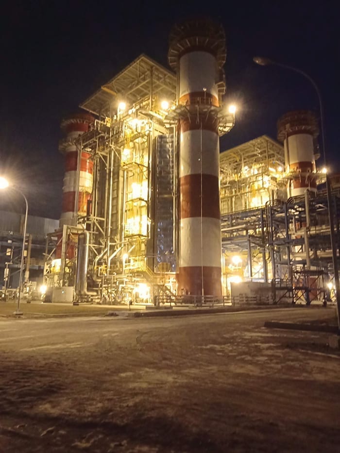
In addition, the plant supplies thermal energy in the form of steam to a local refinery, Tesoro Hawaii, one of only two refineries on the island. Kalaeloa provides 90% of the refinery’s thermal requirements and supplies approximately 20% to 25% of the entire island’s electrical generating capacity. The plant’s output is critical for meeting the energy needs of Oahu, the third-largest of the Hawaiian Islands (Figure 1).
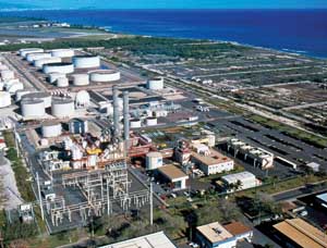
1. Ocean-front property. The Kalaeloa Cogeneration Plant is in the foreground, with the Tesoro refinery’s wastewater treatment facility and fuel tanks behind it. Diamond Head and Honolulu are in the far background. Courtesy: Gary Hofheimer
Plant Profile
The cogeneration facility provides a portion of the steam needs for Tesoro (previously Broken Hill Proprietary). An approximate total hourly production of 100,000 pounds of steam at three pressure levels (700 psi, 450 psi, and 235 psi) can be supplied. Tesoro’s steam requirements qualify Kalaeloa as a cogenerator under the Public Utility Regulatory Policies Act of 1978. The 208 MW of firm capacity net electrical power provided to HECO is provided at 138 kV to the HECO grid via the adjacent CEIP substation.
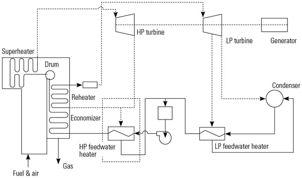
The plant comprises two ABB 85-MW (type 11NM) gas turbines, one ABB 51.5-MW extraction/ condensing steam turbine, two Deltak heat-recovery steam generators (HRSGs), and the balance-of-plant equipment that completes the combined cycle (Figure 2). The primary plant fuel is low-sulfur fuel oil. No. 2 diesel fuel is also used as short-time backup fuel and for start-up and shutdown of each gas turbine. Propane is used for the ignition of each gas turbine.

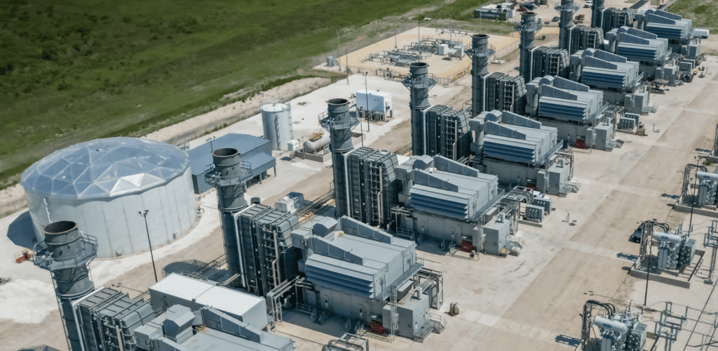
2. Powering Oahu. The Kalaeloa plant entrance with water demineralization plantand demineralization storage tank on the right; the steam turbine, control room, and administrative building on the left; and both stacks of the two combustion turbines in the background. Courtesy: Gary Hofheimer
Overview of Facility Operations
The turbine exhaust gas contains a significant amount of thermal energy that is passed through the HRSGs to produce steam. This steam is passed at two pressures to the high- and low-pressure (HP and LP) steam headers. From there, the steam can be sent in two directions:
-
Bypass around the steam turbine and go directly to the main condenser, go to any one steam line routed to Tesoro, or go to all three of the process steam lines routed to Tesoro; or
-
Go to the steam turbine through pressure-limiting control valves.
Steam entering the steam turbine is expanded to produce electricity in the generator and is then exhausted to the main condenser, where it is condensed by main cooling water.
The Plant’s Limitations
The hot gases from the two gas turbines (GTs) serve the two HRSGs without additional firing. Because no bypass is provided on the hot gas side, it is not possible to operate either of the gas turbines without the water-steam cycle also being in operation.
The plant is intended for baseload operation and doesn’t peak load the GTs. The maximum output is the same for diesel fuel as it is with LSFO.
To protect the steam turbine from excessive temperatures, the HP live steam temperature is limited to 905F by attemperators. The steam turbine bypass and/or the steam turbine inlet pressure controller will protect the plant against inadmissible high rates of change in pressure when disturbances or rapid load changes occur.
The maximum HP live steam pressure is limited by an overload control valve to 1,073 psia. The steam turbine, under normal operating conditions, always generates exactly that output, which is made available by GT waste heat. Therefore, in the combined-cycle plant, without additional firing, the output is only controlled by the amount of fuel supplied to the GTs.
At higher loads, the steam turbine operates in sliding pressure mode, where any excess steam is bypassed to keep the turbine inlet pressure within operating limits. At partial loads, the minimum pressures of 798 psia for HP steam (according to process steam requirements) and 58 psia for LP steam (according to the minimum pressure in the feedwater storage tank) are maintained by throttling the steam turbine control valves.
Four Modes of Operation
The combined-cycle plant can operate in four independent modes: extraction/condensing, straight condensing, mixed process operation of the steam turbine and process bypass, and process bypass.
Extraction/Condensing Operation. This is the normal mode of operation. The steam demands of the three process steam extractions to Tesoro are kept constant by means of a pressure control system for each individual process. For low condensing flows, the pressures are maintained by throttling the steam from a higher pressure extraction. For higher condensing flows, the roles are switched, and the valves in the extraction lines are throttling while the pegging steam control valves are closed. In every process extraction steam line, a water injection system holds the process steam temperature at the tie-in point to the required set value by spraying HP feedwater into the process steam line. The injection water control is of the split range type, with two injection control valves.
Straight Condensing Operation. This operating mode is very simple and is used when no process steam is being supplied to Tesoro. All steam produced in the HRSGs flows through the steam turbine to the condenser and to the feedwater preheaters (minus NOx steam that is extracted from the steam turbine). Due to Tesoro’s steam requirements, this mode is very rarely used; however, it makes available the maximum electrical power for delivery to HECO.
Mixed Process Operation of the Steam Turbine and Process Bypass. This mode of operation occurs at partial load running of the plant. It occurs when the extraction(s) of the steam turbine can no longer meet the process steam demand (pressure) and the electrical power output is therefore limited. The process steam pressure then is held by the HP process bypass line.
Process Bypass Operation. In the event of a sudden outage (trip) of the steam turbine, the process steam bypass will take over the supply of the process steam. Excess steam is redirected to the condenser via the HP and LP steam turbine bypasses. The turbine bypasses (HP and LP), as well as the condenser and cooling system, are designed to operate the two GTs at full load without providing process steam to Tesoro. Electrical power output is then supplied solely by the two GTs.
Problems Associated with Fuel Combustion
The Kalaeloa facility achieves non-corrected plant efficiencies from 44% to almost 45%. It is unique in the type of fuel it burns. In fact, it is the only plant in the entire U.S. that burns low-sulfur fuel oil (LSFO, a #6 bunker fuel) with GT technology. The refinery receives crude oil from which it harvests a number of different products, such as kerosene, diesel, and gasoline. Whatever is left (waste oil) is then typically burned in conventional power plants, such as in power boilers with steam turbines, or even used to make tar. However, in this case it is the fuel the plant burns in its GTs.
The LSFO is relatively high in vanadium (12 to 20 ppm), which has an ash-melting temperature of roughly 1,647F. Because the turbine inlet temperature is 1,854F, the hot temperature corrosion caused by the vanadium deposits damaged the blading and other GT parts. Therefore, the facility staff injected an additive (magnesium) to increase the vanadium ash-softening temperature from 1,647F to roughly 2,175F — well above the turbine inlet temperature — and thereby avoided hot temperature corrosion of the noble parts.
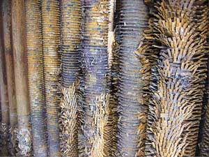
Unfortunately, this chemical process creates a considerable amount of ash. The additive falls out during the combustion process and not only coats the blading (as it should) but also coats the HRSG tubes (as it should not). In fact, not only does the additive coat the HRSG tubes, but it also completely plugs up the tightly finned tubes of an HRSG designed to be operated by GTs burning relatively clean fuels such as diesel (#2 fuel oil) or gas (Figures 3, 4, 5, and 6). The HRSGs are not equipped with adequate cleaning systems to handle the fouling effects of the plant’s fuel and additive.
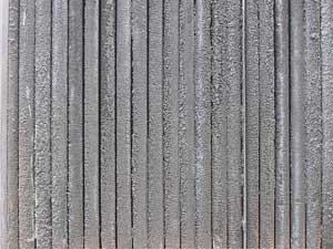
3. Trashed-out tubes. Heavily pluggedup finned tubes. Courtesy: Kalaeloa Partners LP
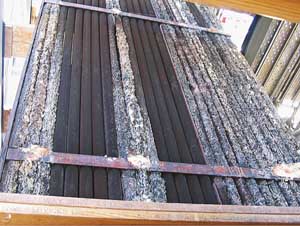
4. The good, the bad, and the ugly.Old panels with some relatively clean tubes and some heavily fouled ones. Courtesy: Kalaeloa Partners LP
5. Corrosion casualties. Tube corrosion due to water cleaning. Courtesy: Kalaeloa Partners LP
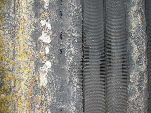
6. All plug and no play. Tubes are bridged and form a solid wall that makes it impossible for hot gases to penetrate. Courtesy: Kalaeloa Partners LP
HRSG fouling so drastically lowered the units’ efficiency that the plant staff was forced to find methods to clean them. In fact, turbine output was sometimes dropping between 2 MW and 4 MW over a one-week period due to ash buildup on the HRSG tubes. Because of this effect, the HRSGs had to be cleaned every weekend in order to regain capacity. The facility personnel experimented with all sorts of cleaning methods, such as high-pressure air, dry ice, grid blasting, CO 2 pellets, and even acoustic cleaning. Nothing worked because of the tightness of the HRSG and its vertical and finned tube design (Figures 7 and 8).
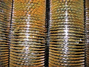
7. Role models. This is what the tubes shown in Figure 3 are supposed to look like: clean and without corrosion. Courtesy: Kalaeloa Partners LP
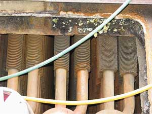
8. In with the new. This shot shows the new tube panels installed with new fin design sitting side-by-side with old tubes on the right. Note the larger space between tubes found in new tubes design vs. the two tubes with the old fin design. Courtesy:Kalaeloa Partners LP
The plant staff finally decided to water wash these "non-water-washable" units and came to the conclusion that water washing was fairly efficient, at least at the beginning. The early success can be illustrated by the following numbers: The plant was designed, new and clean, to produce a plant heat rate at full load (its most efficient mode) of 8,310 Btu/kWh with an HRSG stack temperature of 330F. An acceptable annual heat rate, considering that the plant often runs at part load, would be somewhere around 8,600 to 8,700 Btu/kWh. Compare those figures with the worst condition prior to implementing water washing of 9,100 Btu/kWh at a 410F stack temperature. This meant that approximately 5% more fuel was being used to generate the contractual plant output for which the plant owner could not recover the cost. This translated into approximately two million barrels (bbl) of fuel per year. At $50/bbl, that was costing the owner $5 million extra per year in additional fuel costs.
The first year after water washing was introduced, the plant’s heat rate dropped to 8,630 Btu/kWh, which indicated that plant staff had achieved their goal. However, very quickly the heat rate started to climb again, and only three years later the heat rate was well over 8,700 Btu/kWh and climbing. Not only did the heat rate climb at an alarming rate, but tube leaks also started to appear, and the number of leaks increased very quickly, reaching a total of four per month.
What facility personnel did not understand initially were the detrimental effects that could be caused by water washing, such as acid corrosion. There were many areas in the unit, which is composed of up to 16 tube-bundle-thick boiler sections that were merely moistened without actually washing the debris out of the tube fins and bundles. Consequently, water washing the units established ideal conditions for acid corrosion (because the fuel contains 0.5% sulfur).
During the process of repairing tube leaks, staff were able to see that large areas of the tube panels were not only solidly packed with ash but that the ash was now as hard as rock. Furthermore, when the HRSG went back in operation, the wet ash was placed onto the tubes, and that made heat transfer even worse.
Using a Bold Approach to Conquer Corrosion
The problems began to worsen after the implementation of water washing. The units degraded further, and frequent tube leaks, which at times were quite difficult to repair, started to occur — mostly in the back end of the HRSG, where the cooler sections were located. Facility personnel endured forced outages (often several days long) for tube leak repairs as often as every two weeks. They reached the point where the plant’s reliability was in such jeopardy that they had to come up with drastic measures.
Facility personnel decided that there was only one way to tackle the HRSG problems: Remove entire tube panels from the unit and replace them with new panels with improved fin design to allow for better access between the tubes for the purpose of cleaning (Figure 8). The sections were replaced, starting from the back end of the unit all the way through, including the HP economizer. This was a very difficult task because the plant staff only had four weeks to remove and reinstall more than 20 of these panels, along with a large amount of other unrelated work that had to be performed during the outage.
The plant’s staff had to consider many things in order to remove and replace the old panels, such as removing all drain piping and valves at the bottom of the panels as well as vent piping and valves at the top of the tube panels and the steam drum. Additionally, they had to remove the HRSG roof in order to lift the top-supported panels out of the casing and replace them with new ones.
Another challenge involved the new replacement panels, which arrived at the site placed horizontally on flatbed trucks. The staff needed to construct a special frame in order to position the new panels vertically in order to carry out the operation. This all would take a large amount of time, which they did not have during the outage.
In order expedite the upgrade operation and minimize plant down time, facility personnel performed a large amount of prep work prior to the outage. For example, they built a steel rack and staged all panels vertically and in proper order in this rack (Figure 9). Furthermore, all drain and vent piping with associated valves was prefabricated, as was the roof with the many riser penetrations.

9. Ready to go. The tube panels staged in a rack. Courtesy:Kalaeloa Partners LP
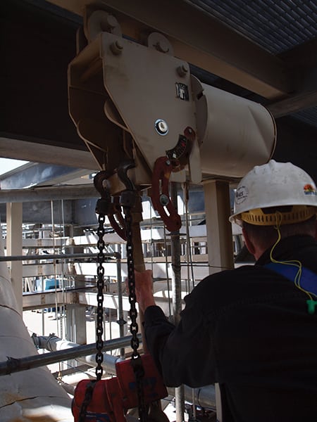
This prep work saved the staff many hours during the outage, when the existing piping and roof were then cut at random in order to be quickly removed. After removing the old piping and roof, the new panels could easily be swung into the HRSG without support frames, because they already were staged in vertical position (Figure 10). The plant outage was scheduled to last a maximum of 35 days, and the staff managed to successfully complete the entire outage in 30 days.
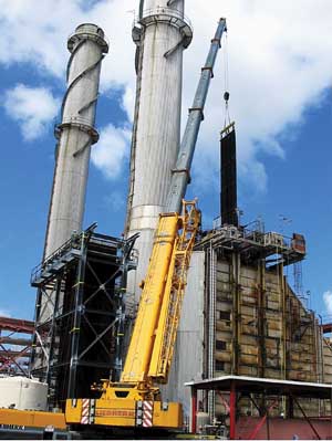
10. An uplifting experience. The old tube panel being removed from the HRSG. The rack with the staged new tube panel is on the left of the yellow crane. Courtesy: Kalaeloa Partners LP
In order to complete all work on both HRSGs, facility personnel had to work during three different outages (one per year) at a total cost of $9 million for labor and materials.
HRSG #2 was tackled first, during the annual outage in 2007. The LP economizer section was replaced with new panels and improved fin design; the HP economizer section was removed and cleaned, and its tube panels were repaired and reinstalled. However, this work did not yield the desired performance improvement. It was therefore decided that during the 2008 annual major overhaul that HRSG #1 should not only receive a new and improved LP economizer but also a new and improved HP economizer and LP evaporator (boiler) section in order to improve performance. Luckily, expectations were met by that change-out.
In order to improve the performance of HRSG #2, the plant staff decided that the HP economizer and LP evaporator would be replaced (as had been done with HRSG #1 in 2008) during the 2009 annual major overhaul in order to improve performance. Again, the anticipated performance improvement was achieved.
The Kalaeloa plant has not had any tube leaks since new replacement panels were installed, and the plant heat rate is now approximately 8,400 Btu/kWh. Using the calculations provided earlier in this article, the reduction in fuel costs for 2007 and 2008 adds up to approximately $6 million. It is anticipated that the $9 million investment will have a payback period of less than three years.
—Hans R. Tobler (hanstobler@aol.com) is the general manager of the Kalaeloa Cogeneration Plant in Kaplei, Hawaii.