The increased use of intermittent renewable energy sources and the shift to gas-fired combustion turbines places new burdens on the dispatch of many coal-fired units. Steam units must now operate at very low minimum load while maintaining the ability to ramp up and down quickly. High-pressure feedwater heater energy control can improve the system response of such coal-fired units.
The regenerative steam cycle with reheat that is used in most fossil fuel–fired steam power plants distributes energy throughout the cycle to improve overall unit efficiency. Reducing certain emissions, such as NOx, is often an added benefit.
A typical subcritical drum-style boiler steam cycle with regeneration and reheat coupled to a high-pressure (HP) and low-pressure (LP) steam turbine with feedwater heaters (FWHs) is illustrated in Figure 1. For this discussion an intermediate-pressure turbine is located between the HP and LP turbines and grouped with the LP turbine. Although only one HP FWH is shown, two or three FWHs following the boiler feed pump are typical, each with a steam supply from an HP turbine extraction port (or HP turbine exhaust, as shown here) or from an LP turbine extraction port. Although only one LP feedwater heater is shown, two or three are typical, each with steam supplied by LP turbine extraction. The deaerator, providing preheated water to the boiler feed pump, also takes steam from LP turbine extraction, linked with an auxiliary steam supply to maintain minimum steam pressure.
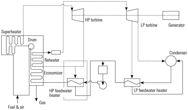 |
| 1. Regenerative steam cycle with reheat. The feedwater heaters use steam extracted from the steam turbine to heat the feedwater. The overall effect is an increase in unit efficiency. Source: Invensys Operations Management |
The use of extraction steam to preheat the feedwater to the boiler reduces the quantity of fuel required to boil the feedwater and generate high-temperature superheated steam, although at the expense of reduced turbine power generation. The boiler reheater next heats a large fraction of the steam exiting the HP turbine to a high temperature prior to entering the LP turbine, producing power more efficiently. A higher reheat temperature improves the efficiency of the LP turbine by minimizing the moisture content in the final stage of the turbine, because moisture degrades the turbine’s mechanical efficiency and the integrity of the blades.
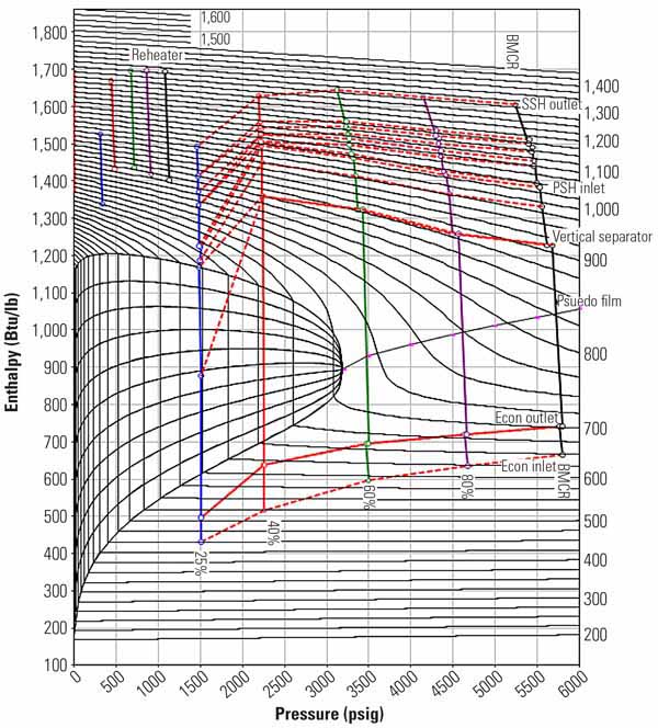
The temperature-entropy (T-S) diagram (Figure 2) illustrates a regenerative steam cycle with reheat operating at 2,400 psig 1,000F main steam entering the HP turbine and 525 psig, 1,000F steam entering the LP turbine (green). The final high-pressure FWH raises the water temperature entering the boiler to 479F. The boiler and feedwater heat inputs and turbine work output, are also illustrated.
 |
| 2. Steam cycle diagram. The typical regenerative steam cycle with reheat is shown on a T-S diagram (green line). Q represents fuel burned to raise the water temperature to make steam and to superheat and reheat the steam. W represents the work produced by the expansion of steam in the various steam turbine stages. The red line illustrates suboptimal cycle operating temperatures. Source: Invensys Operations Management |
Boiler Energy Distribution
During plant design, the entire steam cycle is analyzed; information from the turbine, boiler, and subsystems is combined to specify the design of the boiler, turbine, feedwater heaters, and pumps. The design objective for the boiler is to generate the design superheated steam flow at the design pressure and temperature from the supplied feedwater and the design reheated steam flow at the design pressure and temperature. Drum-style boilers have components with fixed surface areas for each function of the steam process: economizer for water preheating, evaporator for steam generation, superheater for superheating steam, and reheater for reheating steam. These surface areas are selected based on design assumptions for fuel, furnace fouling, and final feedwater temperature. The selection of the number and location of turbine extraction ports for the FWHs also influence the turbine design. The cycle design is based on efficiency considerations balanced by plant equipment capital costs. The design process establishes an energy distribution and temperature profile for the boiler components.
The overall steam cycle is designed for peak efficiency at a single full-load operation point, but the boiler and turbine controls are usually sufficiently flexible that the plant can maintain near-peak efficiency over a range of operating regimes. Arguably the most important control parameters are the boiler steam temperature control systems, which usually include:
- Superheat sprays and reheat sprays cooling steam to an operator-selected setpoint.
- Gas path dampers or gas recirculation to distribute gases to specific sections of the boiler.
- Burner tilt angle, which directs the location of combustion within the furnace, thereby influencing the energy distribution.
- The number of burners in service at any time, which affects the location of combustion heat release.
However, these typical systems may be inadequate to reach and maintain design superheat steam temperatures at all operating points due to other overriding factors, such as fuel quality or flow, boiler design changes, emissions limitations, boiler cleaning practices, and the effects of cycling on furnace heat release.
Fuel Quality Changes or Coal Mills Out of Service Change Fuel Flow. Fuel quality changes or coal mills out of service can result in a shift of the energy distribution within the furnace. For example, an increase in fuel heating value or lower coal mill out of service may raise the combustion zone temperature and NOx, causing greater heat release in the waterwall (evaporator) section of the boiler. The combination of higher steam generation rate and lower gas energy per unit of heat input to the superheater may lower the attainable superheat and reheat steam temperatures to well below design.
Boiler Modifications Change Heat Release. Over the course of the life of the boiler, major modifications to boiler sections may affect the boiler’s ability to achieve design steam temperatures. One example is the replacement of the economizer with a more effective heat exchanger that increases the outlet water temperature that is then sent to the steam drum. This replacement reduces the evaporator energy requirement to generate steam, increasing steam production per unit of fuel. Higher steam flow through the superheater per unit of fuel, with no increase in gas energy to the superheater, adversely affects the ability to attain design steam temperatures.
Emissions May Limit Boiler Operation. The amount of emissions allowed may limit the range of in-furnace temperature controls. In-furnace steam temperature controls, such as burner tilt angle, shift the energy distribution between sections of the boiler. However, burner tilt angles may have adverse consequences on the combustion process, air/fuel mixing, and CO and NOx emissions.
Sootblowers Are Not Effective. The daily operating profile for traditional coal-fired power plants has shifted substantially in recent years due to the availability and low cost of natural gas and increased utilization of renewable power generators. Nightly load shedding to minimum load and unit shutdowns have a major impact on the cleanliness of the furnace and energy distribution. For example, the waterwall section may completely shed its normal fouling, resulting in excessive steam production per unit of heat input on the following startup or load ramp.
Boiler Cycling Changes Furnace Fouling. Frequent load shedding or shutdowns may change the pattern of furnace fouling, changing the energy distribution within the furnace and limiting steam temperatures. Multivariable steam temperature control systems have been commissioned that maximize the integrated performance of the available steam temperature control systems and provide the platform for adding additional control elements in the future to further enhance unit performance.
HP FWH Energy Control
For the purposes of illustrating the usefulness of FWH energy control, comparative operating scenarios are presented. From the design point systems described in Figure 2, assume steam temperatures below design, which introduces a loss of cycle efficiency. If steam temperatures were 970F, for example, then the cycle diagram is as presented in red on Figure 2. Lower steam temperatures reduce the work produced by each turbine, indicated by the enthalpy difference. Also, the LP turbine exhaust is shifted toward higher moisture, which is in practice a less-efficient operating range for the last stage of a steam turbine. The net impact is a loss of thermal efficiency and power generation capability when compared with design.
For drum boilers, boiler feedwater temperature directly affects superheater steam temperature. Cooler feedwater reduces the steam generation per unit of energy supplied to the evaporator. Lower steam generation allows the superheater to increase the outlet steam temperature per unit of energy supplied to the superheater. Calculations and actual test results indicate approximately a 1:1 relationship, that is, a 1 degree Fahrenheit superheat increase for each 1 degree F cooler feedwater. Therefore, feedwater temperature control can be applied to augment the regulation of superheat steam temperature. Because the energy provided to the HP FWH establishes the final feedwater temperature (the temperature of the water entering the boiler), regulation of the energy to the HP FWH is a possible component of multivariable boiler/turbine control.
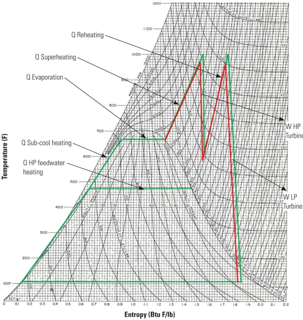
The T-S diagram in Figure 3 illustrates the lowering of the feedwater inlet temperature from design and the subsequent increase in superheat and reheat steam temperatures to the design point (shown in blue). The FWH outlet temperature is reduced from the design value of 479F to 449F and the HP FWH temperature rise is lowered to 60% of design. The superheat and reheat steam temperatures are increased from 970F (shown in red) to the design 1,000F. Because less-cold reheat steam is used by the HP FWH, more steam flows through the reheater, resulting in more LP turbine work per unit of superheat steam. Both internal calculations and test results indicate a net increase in efficiency in conjunction with higher load generation per unit of superheat steam production.
 |
| 3. Revised steam cycle. The typical regenerative steam cycle with reheat operating suboptimally is illustrated on a T-S diagram (red line). The blue line illustrates the effect of lowering the feedwater inlet temperature, which increases the superheat and reheat temperatures back to design, producing more incremental work by the LP steam turbine. Source: Invensys Operations Management |
In the commonly experienced situation where steam temperatures are lower than design at full load, the HP FWH energy control serves to adjust the cycle to achieve its design steam temperatures. The efficiency gains from higher steam temperatures more than offset the efficiency loss from cooler feedwater temperature. The system raises peak load generation capability, both short-term and long-term grid dispatch, through increased load generation per unit of superheat steam from higher LP turbine steam flow.
The application of the HP FWH energy control provides an additional means of increasing steam temperatures. Other steam temperature controls that may have adverse consequences on combustion emissions, for example, burner tilts, can be modulated to more favorable positions for reduced CO and NOx emissions. Also, in-furnace controls may sacrifice boiler efficiency by diverting energy from the evaporator to the downstream surfaces, thereby resulting in a higher exit gas temperature. By applying HP FWH energy control, the in-furnace controls can be adjusted for higher boiler efficiency and lower emissions.
Energy Control Test Results
To confirm the calculated performance results, a test was conducted of a coal-fired unit at full load. Figure 4 illustrates the results of a test of the HP FWH energy control applying partial closure of both parallel high-pressure feedwater heater extraction isolation valves. Specifically, the HP FWH energy control system pinched back the extraction valves one at a time to produce a 50 psi drop across each steam extraction line. The objectives of the test were to confirm the:
- Expected drop in feedwater outlet temperature.
- Predicted increase in superheater steam temperature.
- Predicted increase in reheat steam flow.
- Predicted reduction in superheated steam flow and associated turbine throttle valve position while maintaining the same load generation.
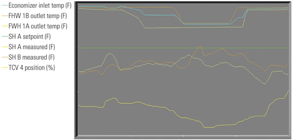 |
| 4. Test 1 results. The first test was based on a HP FWH energy control system modulating the extraction steam supply. The unit responded with improved steam temperatures, as expected. Source: Invensys Operations Management |
The trend lines illustrate the positive response of the 1A and 1B feedwater heater (parallel heater trains) outlet water temperature, the economizer water inlet temperature, the A/B superheater steam temperatures (two superheater sections) and the Unit 4 turbine valve position demand signal. Test results confirmed the program predictions.
A second test was conducted with full isolation of the HP feedwater heaters (1B and 2B). Figure 5 illustrates the trend results for 1A and 1B feedwater heater outlet water temperature, economizer water inlet temperature, A/B burner tilt positions, percentage of NOx, A/B superheater steam temperatures, Unit 3 and Unit 4 turbine valve position demands, reheat spray flow, and A/B air heater gas outlet temperature. In this test the burner tilts were adjusted downward to maintain superheat steam temperatures in the prior range. The test encompassed four hours to allow sufficient settling time for the process. Sootblowing and other normal controls were maintained throughout the test (Figure 6).
The test results illustrate the key variables before and after isolation of HP feedwater heater 1B:
- Confirmed the predicted drop in economizer inlet temperature, 46F.
- Lowered the burner tilts required to maintain superheat steam temperatures by 12F.
- Lowered NOx emissions by 12%.
- Lowered the furnace exit gas temperatures by 14F.
- Increased the reheat steam flow.
- Lowered the reheat spray flow by 25,000 lb/hr.
- Reduced the superheat steam flow and corresponding turbine throttle valve position.
- Increased the load generation margin as related to turbine throttle valve position.
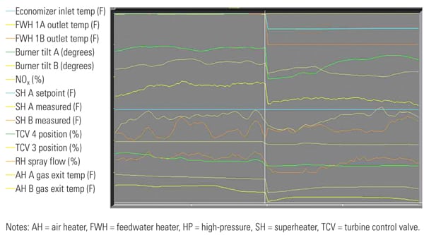 |
| 5. Test 2 results. The second test fully isolated the first and second HP FWHs. Source: Invensys Operations Management |
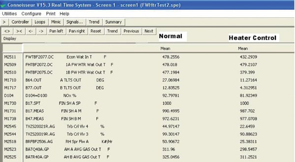 |
| 6. Good operating data. A screen grab of the plant control system shows the plant performance with and without the HP FWH 1B in service. Note that superheat temperatures are up, NOx is down, and desuperheater spray water is down—all indications of more efficient unit operation. Source: Invensys Operations Management |
HP FWH energy control can compensate for the adverse impact of higher-Btu coal, using less-than-ideal coal mills due to equipment outages, boiler component replacement, load cycling, and other conditions averse to attaining design steam temperatures. Tests also confirm that peak load generation capability can be significantly increased through HP FWH energy control with little, if any, consequence on the unit heat rate. The estimated potential increase in load generation is up to 7%, depending on cycle design and equipment limitations.
For units that do not have a steam temperature deficiency, including once-through units, the efficiency impact of cooler feedwater is mitigated by the increased boiler efficiency and reheat steam flow through the LP turbine.
HP FWH energy control can be a vital component of a multivariable boiler, load generation, emissions, and steam temperature control system. With the additional advantage of increased sustainable power generation and reduced furnace NOx emissions, the potential benefits are substantial.
— Donald Labbe, PE (donald.labbe@invensys.com) is a consulting control engineer for Invensys Operations Management, based in Foxboro, Mass. He is an ISA Fellow and director for ISA POWID. This article is derived from a technical paper presented at the 2012 ISA POWID Conference.