ASME’s latest revision of its Recommended Practices for the Prevention of Water Damage to Steam Turbines Used for Electric Power Generation: Fossil-Fuel Plants, ASME TDP-1-2006, contains much important design and operating advice that is proven to protect steam turbines. However, many in the industry are not as familiar with the update as they should be. This article provides a concise overview of this critical design standard.
ASME TDP-1, Recommended Practices for the Prevention of Water Damage to Steam Turbines Used for Electric Power Generation: Fossil-Fuel Plants, was initially developed in response to a rash of water induction incidents in the 1960s as power plant ratings were scaled up above 150 MW. TDP-1 was originally published in 1972; revisions were made in 1979, 1985, 1998, and 2006. The latest revision to TDP-1 includes conventional steam (Rankine) cycle and combined-cycle power plants. (Nuclear power plants are covered under TDP-2.)
TDP-1 is a recommended practice and therefore not a mandatory code; if you want the features described in TDP-1 to be included in your plant design specifications, it must be specifically called out in your contract. Merely writing into your plant specifications the requirement to "comply with all ASME standards" will not automatically include this recommended practice.
Sources of Water Induction
Water can be inducted into a steam turbine from several sources, including these:
-
Motive steam systems
-
Steam attemperation systems
-
Turbine extraction/admission systems
-
Feedwater heaters
-
Turbine drain systems
-
Turbine steam seal systems
-
Start-up systems
-
Condenser steam and water dumps (steam bypass)
-
Steam generator sources
Figure 1 shows the percentage of water induction incidents attributed to the most common sources of water in conventional steam cycles. Although water induction into high-pressure (HP) and intermediate-pressure (IP) turbines has historically been recognized as the most damaging, experience has shown that water induction into low-pressure (LP) turbines can also cause significant damage and should be taken seriously.
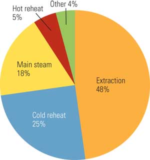
1. Sources of water induction. Source: Serge P. Barton et al., “A Water Induction Monitor for Steam Turbines” (ASME)
Water induction can happen at any time; however, it is most common during transients such as those that occur during start-up, shutdown, and load changes. Figure 2 illustrates the percentage of times various events contribute to water induction for a conventional steam cycle. It is interesting that only 18% of water induction incidents occur when the unit is at load.
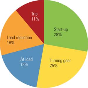
2. When water induction occurs. Source: Serge P. Barton et al., “A Water Induction Monitor for Steam Turbines” (ASME)
When water induction does occur, it can damage steam turbines in several ways. The damage is usually caused by the impact of large slugs of water or by the quenching effect of cold water on hot metal. The severity of water damage can vary from minor seal rubs all the way to catastrophic damage to the turbine. Generally, water damage falls into the following categories:
-
Thrust bearing failure
-
Damaged blades/buckets
-
Thermal cracking
-
Rub damage
-
Permanent warping distortion
-
Secondary effects, including seal packing ring damage, pipe hangar and support damage, and damage to instrumentation and controls
TDP-1 Basic Concepts
TDP-1 offers guidance on how to identify systems that have a potential to allow water to enter the turbine and to design, control, maintain, test, and operate these systems in a manner that prevents any significant accumulation of water — the first line of defense in preventing turbine water damage. However, malfunctions do occur, so TDP-1 offers recommendations for preventing turbine damage that include:
-
Detection of the presence of water either in the turbine or, preferably, external to the turbine before the water has caused damage.
-
Isolation of the water by manual or, preferably, automatic means after it has been detected.
-
Disposal of the water by either manual or, preferably, automatic means after it has been detected.
The philosophy of TDP-1 has been and will continue to be that "no single failure of equipment, device, signal, or loss of electrical power should result in water or cold steam entering the turbine."
The latest revision of TDP-1 includes several new items that address recent industry experience, including combined-cycle units and the application of modern control systems and technology to turbine water damage protection. The new guideline addresses:
-
Combined-cycle configurations such as HP, IP, and LP drums on heat-recovery steam generators (HRSGs).
-
Cascading and direct turbine bypass systems.
-
Recommendations for process steam lines associated with cogeneration configurations.
-
Recommendations on superheat attemperation at the outlet of the final superheater of an HRSG.
-
Additional clarification of system drain requirements, including the use of drain flash tanks and pumped condensate drain tanks.
-
Recommendations for draining side and axial turbine exhaust orientations into the condenser.
-
The use of integrated control systems (ICS), such as distributed control systems (DCS), in closed and open feedwater heater level instrumentation and controls. It also expands on the control and automation criteria for turbine water induction protection systems.
To facilitate the discussion of combined-cycle configurations, TDP-1-2006 introduces the concept of "motive steam." Motive steam systems supply steam to a steam turbine for the primary purpose of power production or to an auxiliary turbine such as a boiler feed pump drive turbine. The committee introduced the concept of motive steam to incorporate combined-cycle configurations (HP, IP, and LP drums) along with the existing conventional steam (Rankine) cycle configurations.
Motive steam systems include:
-
Main steam
-
Hot and cold reheat steam
-
HP, IP, and LP steam
-
Admission steam
Motive steam systems do not include:
-
Extraction steam
-
Gland steam seal line
Recommendations for Combined-Cycle Configurations
In this document, a combined cycle is defined as a hybrid of the gas turbine (Brayton) and steam (Rankine) cycles. Waste heat contained in the gas turbine exhaust is fed through an HRSG that produces steam that is expanded through a condensing steam turbine to produce power.
Heat-Recovery Systems. HRSG system configurations typically include as many as three steam drums, each with boiler water level controlled by feedwater valve modulation and condensate or feed pump recirculation or a similar method of controlling inflows. The same plant design requirements that apply to other steam generators apply to HRSGs.
The use of attemperators external to the steam generator, downstream of the last superheating (or reheating) element, is discouraged; however, it is recognized that under some conditions it cannot be avoided. When this type of attemperator is required in the motive steam line to control the temperature of the steam entering a steam turbine, several additional features are recommended to provide adequate protection.
When the gas turbine cooling steam or power augmentation steam pipe is connected to a motive steam line, this pipe should not be connected at or near the low point of the motive steam pipe. If routing of this pipe creates a low point, a drain should be provided from the pipe.
Turbine Bypass Systems. Turbine bypass systems should be provided with the same level of protection as motive steam piping. These should include drains and drain pots (if applicable) with power-operated drain valves. Attemperators in bypass systems that discharge to the cold reheat system (or any other line connected back to the steam turbine) should be designed consistent with all the requirements on attemperators. Non-return valves should be provided in the cold reheat system to prevent the reverse flow of bypass steam into the steam turbine. Designers should carefully consider the location, design, and orientation of large steam dumps (such as turbine bypasses) into the condenser.
Process (Cogeneration) Steam. Process steam lines that are supplied from motive and extraction steam lines are a potential source of water induction. Motive and extraction steam lines should be protected from process steam lines with the following features:
-
Two power-operated block valves should be provided to isolate the motive steam or extraction steam line from the process steam line. Any two of the following are acceptable: a pressure-reducing valve (control valve) with fail-closed capability against the maximum reverse differential pressure; a power-assisted non-return valve; and a standard power-operated block valve.
-
The designer should consider steam supply and process system upsets that may result in cold steam admission to the motive/extraction steam line.
-
If an attemperator is required, it should be located downstream of the second power-operated block valve.
Recommendations for Steam Line Drains
There are three types of steam line drains regardless of the configuration of the steam power plant:
-
Standard with power-operated block valve
-
Drain pot with power-operated block valve
-
Drain pot with redundant level elements and power-operated block valve
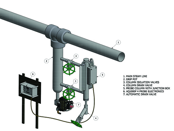
Figure 3 shows a typical drain pot with redundant level elements typically used in "high-risk" areas. One change in the guideline is the level-sensing device, which now is labeled as a level element (LE). In past versions of the guidline this device was shown as a level switch. The level element in the latest version can represent either a level switch, a thermocouple, or a conductivity probe.
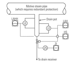
3. Stay level-headed. Typical drain pots must have redundant level elements. (Symbols per ISA standards.) Source: ASME TDP-1-2006
Drains should be installed at each low point in motive steam piping. Placement of drain pots is recommended at:
-
Cold reheat lines at the first low point downstream of the steam turbine exhaust. (This application requires redundant level elements.)
-
Motive steam lines that operate (admit steam to the steam turbine continuously) with less than 100F (56C) superheat, unless a continuous drain has been provided. (This application requires redundant level elements.)
-
Motive steam lines with attemperators (for example, an attemperator in an HP steam line). The drain pot should be between the attemperator and the steam turbine. (This application requires redundant level elements.)
-
Motive steam lines that are prone to water accumulation during operation for which large drain collection areas and/or water-detection devices are desired.
-
Motive steam lines that will be under vacuum during steam turbine start-up and shutdown.
-
Branches and legs that will be stagnant during various operating modes, unless a continuous drain has been provided.
-
At the steam turbine end of long horizontal runs (over 75 feet).
Recommendations for Automatic Drain Control Systems
As plants become more complex and a larger number of drains are involved, plants are adding automatic controls to simplify operation. Any automatic control system used to control steam line drain valves identified in these guidelines should be designed so that the system has a means of initiating automatic valve actuation and a separate means of verifying the appropriateness of the automatic action. If an inappropriate action is taken, an alarm should be provided. For example, if a drain valve is closed automatically based on a timer, an instrument other than the timer, such as a level switch that would alarm if water were still present in the steam line, should be used to verify that the timer initiation was appropriate.
A typical condensate tank is shown in Figure 4. Critical tank design issues include vent sizing, redundancy of controls, and redundancy of pumping equipment, including independent power supplies. The following recommendations apply:
-
The cross-sectional area of the drain tank vent should be large enough to make certain that the tank’s internal pressure, with all simultaneous drains open, will be lower than that of the lowest pressure drain into the tank under all operating conditions, including start-up and shutdown.
-
When the drain tank is connected to the condenser, the drain tank should provide separation of entering condensate and steam from the drain source(s). The vent line to the condenser should be large enough so that the tank pressure will be less than the source pressures of all drains connected to the tank under all conditions. Under start-up and shutdown conditions, some of the drains may be close to condenser pressure.
-
The tank drain line should be sized for the maximum service conditions. When a drain pump is required, it should be actuated automatically based on drain tank level. If a drain pump is required and its failure could possibly lead to water entering the turbine, redundant drain pumps (supplied with power from separate power sources) should be furnished, each controlled by an independent level controller actuated automatically based on drain tank level. Independent level signals indicating a high-high alarm condition in the tank should be provided in the control room.
-
Connections for incoming drains on the tank should be located above the maximum water level in the tank.
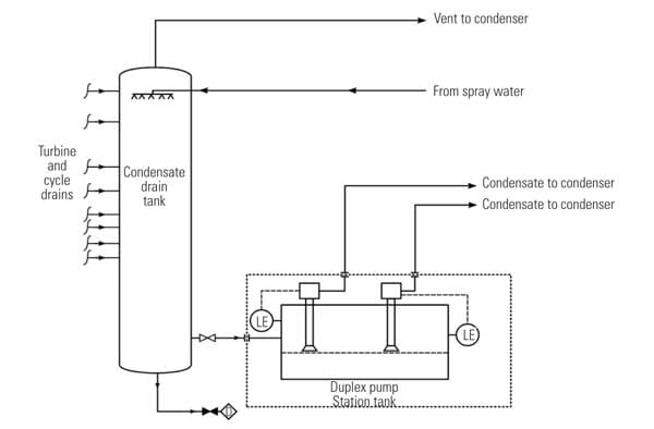
4. Double up components. The new specification provides sizing and redundancy requirements for a vacuum condensate drain tank. Source: ASME TDP-1-2006 Committee
Steam Turbine Exhaust Configuration
Axial and side exhaust can be used to lower the turbine pedestal and minimize plant cost (Figure 5). But compared to a down exhaust condenser, this configuration adds risk because of the proximity of condenser water level to turbine blades.
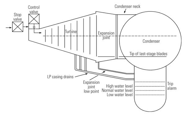
5. Keep your blades dry. This illustration of an axial exhaust steam turbine with condenser drains and water levels is used to show that water should never accumulate higher than the tip of the last-stage blades. Source: ASME TDP-1-2006 Committee
Because of the axial and side exhaust steam condenser’s relatively compact design and close proximity to the steam turbine exhaust, condenser designers should carefully consider the location, design, and orientation of large steam dumps (such as turbine bypasses) into the condenser. This is necessary to avoid or minimize the injection of large, and potentially damaging, quantities of water into the steam turbine exhaust.
The steam dump should be designed to disperse sufficient incoming steam energy to avoid backflow toward the turbine. Considerations should include, but not be limited to, desuperheater station placement and placement and configuration of high-energy steam dumps to avoid velocity vectors toward the steam turbine and to achieve maximum possible steam dispersion. Criteria that should be considered include the following:
-
Avoid discharging high-energy bypass steam into the area between the condenser hotwell and the tube bundle.
-
Locate the bypass sparger a safe distance from the condenser tube bundles to allow a sufficient reduction in kinetic energy so that high-energy steam does not reach areas above and below the tube bundles and cause a recirculation backflow with entrained water toward the turbine (Figure 6).
Determine an incidence angle of high-energy steam jets that will avoid reflected velocity vectors toward the turbine exhaust.

6. Unwanted water. An axial exhaust steam turbine must avoid recirculating water back into the steam turbine. Source: ASME TDP-1-2006 Committee
Recommendation for Integrated Control Systems
In the ASME standard an ICS is defined as a control system featuring multiple processors, input/output modules, and memory storage interconnected through a communication network and equipped with redundant power supplies. Normally, a DCS or redundant programmable logic controllers will meet this requirement.
The minimum ICS features to meet the reliability and redundancy needs addressed in this recommended practice are:
-
Dual processors.
-
Uninterruptible power supply.
-
I/Os associated with redundant plant equipment and instruments should not be connected to the same I/O cards.
-
Outputs that fail to known position during processor or internal communication failure.
More to Come
The committee is now working on TDP-2 for nuclear power plants. Look for it in the near future.
—Larry A. Kielasa, PE recently retired from DTE Energy and was the vice chair of the ASME Water Induction Prevention Committee that prepared TDP-1-2006. Ram Narula (rnarula@bechtel.com) is a Bechtel fellow, vice president, and chief technology officer for Bechtel Power. He chaired the committee. John C. Boyle, PE (john.boyle@fmglobal.com) is a senior engineering technical specialist for FM Global.