Austin Energy replaced the selective catalytic reduction (SCR) catalyst twice over five years for its four peaker turbines. The duct modifications and injection grid redesign, combined with new catalyst, are producing high NOx reduction and low ammonia slip, and the catalyst is now expected to last at least five years.
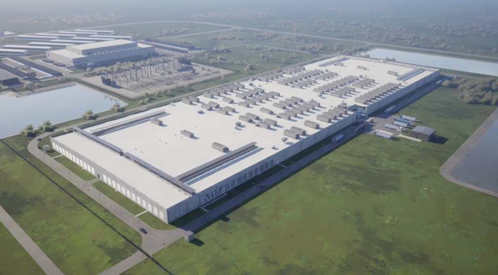
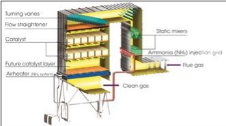
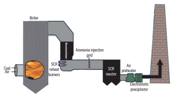
Austin Energy (AE) owns the Sand Hill Energy Center (SHEC), a 500-MW power plant with a natural gas combined-cycle unit and four simple-cycle peaking combustion turbines. With typical high summer demands for the growing Austin area and record electric peaks in 2009, SHEC relies on its four General Electric LM-6000 combustion turbines for on-demand capacity. Those turbines together experience approximately 350 start/stops per year. As shown in Figure 1, each combustion turbine has a dedicated selective catalytic reduction (SCR) unit for NOx reduction to meet the plant’s stack emission permit limits.
 |
| 1. Four peakers. Austin Energy’s Sand Hill Energy Center includes four 50-MW simple-cycle combustion turbines for peaking service that are equipped with SCRs. Also present on the plant site is a 480-MW combined-cycle plant. Work is under way to add two additional 50-MW peaker combustion turbines with start-up scheduled later this year. Courtesy: NEPCO |
In 2006, after the SCR catalyst in the peakers had been replaced twice over a period of five years, AE decided to take a closer look at SCR catalyst performance. A study of operational data along with chemical analysis of the catalyst showed significant catalyst deterioration had occurred. AE issued a request for proposal and scope of work that covered measuring/modeling flue gas velocity distribution, evaluating the design of the ammonia injection grid (AIG), and replacement of existing wash-coated catalyst with extruded homogenous SCR catalyst. The performance requirements for the new catalyst design were 90% NOx reduction with 5 ppm ammonia slip for a period of five years or 15,000 hours of operation.
After careful evaluation of proposals, Cormetech Inc. was selected by AE to provide the SCR catalyst product replacement and to evaluate overall system performance. A three-phase project approach was recommended in July 2007. The remainder of this article reports the results achieved for each of the three project phases.
Phase I: Investigation and Evaluation
Cormetech’s testing of the existing catalyst samples confirmed that deactivation was severe and attributable to loss of the wash coat and sodium poisoning. The deteriorated condition of the catalyst confirmed that SHEC would need to take action in order to replace the catalyst in order to ensure meeting its emission requirements.
In addition, an initial inspection of the AIG lances revealed that the injection holes were 12 inches from either side of the duct walls (Figure 2). This injection gap was causing a starvation of ammonia to a portion of the flue gas stream, thereby permitting flue gas to pass through the SCR system essentially untreated.
 |
| 2. Just passing by. An inspection of the ammonia injection grid lances found that ammonia was not thoroughly mixing with the flue gas, thereby allowing a portion of the gas stream to pass through the catalyst untreated. This figure illustrates a “two-prong” ammonia injection grid design (AIG). Courtesy: Cormetech |
Test ports were installed on Unit 1 to complete the performance assessment. The ports were located in three areas: downstream from the SCR catalyst, upstream from the SCR catalyst, and upstream from the AIG. Flue gas testing was completed to assess velocity, temperature, and ammonia to NOx variation. This testing confirmed a maldistribution of ammonia within the flue gas stream as well as poor distribution of flow and temperature at medium- and low-load conditions.
The catalyst condition and flue gas test results were reviewed in September 2007. Following this review, SHEC requested expedited delivery of the replacement catalyst to meet its planned December 2007 maintenance outage schedule. At the same time, SHEC authorized commencement of the Phase II process modeling to understand the flow and ammonia distribution concerns.
During the December 2007 outage, turnkey SCR catalyst replacement was completed in less than two weeks, with 12 new custom-designed modules installed within each of the four units (Figure 3). For each unit, a sample tray was incorporated to allow for easy removal of catalyst samples for evaluation, as shown in Figure 4. During future outages, the samples can be quickly removed and a replacement catalyst element installed. The sample is then returned to Cormetech for analysis and to assist with catalyst management planning. This approach precludes the need for rigorous drilling of the catalyst to extract core samples.
 |
| 3. Complete replacement. The SCR assemblies for all four combustion turbines were replaced in less than two weeks during the December 2007 outage. Courtesy: Cormetech |
 |
| 4. Process improvement. A sample tray was added to each of the new catalysts to ease access when collecting catalyst core samples for laboratory analysis. Drilling of the catalyst to collect a sample is no longer required. Courtesy: Cormetech |
Also during this work, sample ports were installed downstream of the SCR catalyst in the three remaining units. The SCR systems on all units were successfully started up and met site emission requirements for 90% NOx reduction; however, ammonia emissions were higher than the design predicted.
A simplified test was run after start-up that revealed significant ammonia to NOx stratification requiring further investigation. Inadequate ammonia:NOx distribution can pose problems of inadequate NOx reduction, higher ammonia usage, and localized regions of high ammonia slip.
Phase II: Process Modeling and Design Improvement
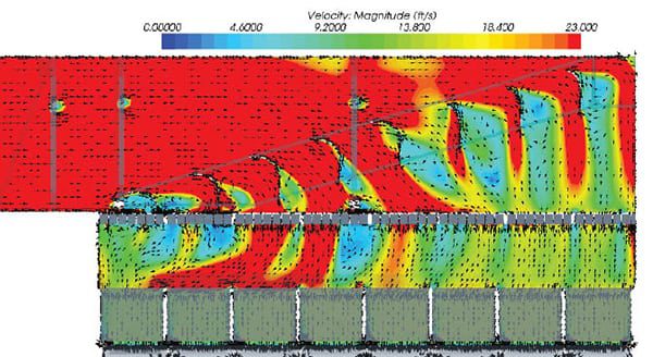
A computational fluid dynamic (CFD) study was conducted to both quantify the existing ammonia:NOx distribution within the SCR reactor and to assess the potential design improvements. The existing AIG system consisted of 11 two-pronged lances designed with 22 single, 3/16-inch-diameter injection holes orientated to direct ammonia parallel to the flue gas flow, aimed directly at the SCR catalyst inlet.
Figure 5 illustrates the baseline ammonia distribution within the flue gas stream as predicted by the CFD analysis. The three panels show the ammonia mixing as it approaches the SCR catalyst—the gas flow is perpendicular to the page with each panel located downstream of the ammonia grid as indicated. This modeling indicates significant nonhomogeneity of ammonia in the flue gas at the SCR catalyst inlet. The original AIG design produced stratification, providing a ribbon-like effect where ammonia mixing was limited.
 |
| 5. Out with the old AIG. CFD analysis of the existing ammonia injection grid found significant nonhomogeneity of ammonia in the flue gas at the SCR catalyst inlet. This stratification is seen by the ribbon-like effect (from front to back of the catalyst), where ammonia mixing was limited. Shown in the figure is the relative ammonia concentration in the flue gas. Each figure is a cross-section of the flue gas path measured downstream from the AIG. Source: Cormetech |
The CFD model was then modified to incorporate improvements designed to optimize mixing by changing AIG parameters such as nozzle spacing, nozzle diameters, and spacing between lances. Figure 6 shows the predicted ammonia distribution for the improved design. The figure shows that the stratification has been eliminated and that the ammonia distribution at the SCR catalyst inlet was substantially improved.
 |
| 6. In with a new AIG. The CFD models found that a modified AIG design would significantly improve mixing of the flue gas with ammonia. The results found that the stratification (Figure 5) was eliminated and that the ammonia distribution at the SCR catalyst inlet was substantially improved. Source: Cormetech |
Phase III: Catalyst Replacement and Optimization
As a result of the successful process modeling, recommendations were made for replacing the existing two-prong design AIG (Figure 7) with a three-prong design, as shown in Figure 8. The new lances also employed an optimized nozzle pattern and size. Cormetech also designed new sidewall baffles to eliminate bypass of untreated flue gas along the reactor sidewalls. These design recommendations were accepted by SHEC. The proposed modifications were installed on a single combustion turbine, Unit 3, to test and confirm the benefits of these changes.
 |
| 7. Out with the two-prong lance. The original ammonia injection grid used two lances attached to a single ammonia supply header, a “two-pronged” design (Figure 2). Courtesy: Cormetech |
 |
| 8. In with a three-prong lance. The new “three-prong” design added an additional AIG lance on each header where two had been used previously (Figure 7). Sidewall baffles were also added to improve ammonia mixing with the flue gas. Courtesy: Cormetech |
As a final step prior to implementation of the modeled changes, Cormetech first performed full-load NOx reduction baseline testing. A test plan was developed to operate Unit 3 at full load and perform sampling across the duct cross section. The flue gas characterization was completed through a series of sampling measurements taken across the duct (side to side) and repeated at different elevations (vertically). The goal was to access the effective ammonia:NOx molar ratio distribution, which is a key input parameter to a successful SCR when operating at high efficiency and low ammonia slip. Testing before modifications revealed, as suspected, a poor ammonia:NOx distribution of approximately 30% RMS, further verifying the CFD model result and field observations.
Unit 3 was then modified during the site’s planned fall maintenance outage. The AIG lances were replaced and sidewall baffles were installed. Two weeks after the outage was completed, flue gas testing was repeated. Results showed a significant ammonia:NOx distribution improvement from the original 30% RMS to 7% RMS. The improvements to the ammonia injection system are estimated to save more than 11% in the annual operating costs for aqueous ammonia. Further, the improved ammonia:NOx distribution will effectively extend the operating life of the SCR catalyst by allowing the margin previously needed to compensate for poor distribution to be used to compensate for catalyst deterioration over time.
Given the successful evaluation of the improved system, similar changes were made on the remaining three units during the regularly scheduled spring 2009 outage.
With the new high-performance catalyst and ammonia injection modifications complete, performance tests were conducted under full load and at design conditions (2.5 ppm outlet NOx ). Operational testing confirmed outlet NOx levels trended at 2.5 ppm and the ammonia slip remained below 5 ppm, meeting all performance guarantees (Figure 9).
 |
| 9. Under the limit. Unit 3 performance test results with the new catalyst and AIG modification at full load are illustrated. Testing confirmed outlet NOx levels trending at 2.5 ppm and the ammonia slip remained below 5 ppm meeting all performance guarantees. Source: Cormetech |
Following 2,660 hours of operation, the activity of the high-performance SCR catalyst continues to be exceptional, with NOx reductions exceeding 92% at 5 ppm ammonia slip, showing no degradation in performance from the new condition. A second catalyst test is scheduled after approximately 5,000 hours of operation.
—Terry McTernan, PE (mcternanht@cormetech.com) is manager of project management for Cormetech.