Selective catalytic reduction (SCR) projects often focus on the final NOx emissions levels achieved, but a successful project is about much more than that. Facility owners must consider the complete scope associated with an SCR installation, from supply chain issues and ultra-low NOx emissions levels to customization requirements associated with a given application’s pressure drop constraints and flow distribution. Selecting a single supplier to provide the entire SCR system design under one contract, wrapping all guarantees, can reduce overall project risk and cost. Petroleum refinery and power plant applications for SCR technology typically feature a number of characteristics that highlight the importance of an integrated approach to SCR design and installation.
SCR Basics
SCR technology has proven itself in many industries as an effective means for NOx reduction from both stationary and mobile sources. The basic principle of SCR is the reduction of NOx to nitrogen (N2) and water (H2O) by the reaction of NOx and ammonia (NH3) within a catalyst bed. The primary reactions occurring in SCR are given below:
4 NO + 4 NH3 + O2 —> 4 N2 + 6 H2O
2 NO2 + 4 NH3 + O2 —> 3 N2 + 6 H2O
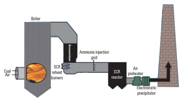
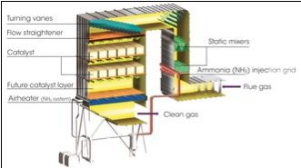
In the SCR process, a catalyst facilitates a chemical reaction between NOx and ammonia to produce nitrogen and water. As shown in Figure 1, an ammonia-air mixture is injected through an injection grid into exhaust gases containing NOx. The gases mix thoroughly by ways of injection design or in a turbulent zone, and then pass through the catalyst where the NOx is reduced. The process is termed “selective reduction” because it takes oxygen from nitrogen compounds only and not from carbon, sulfur, or other oxygenated compounds. The catalyst promotes the reaction but is not consumed by it.
The ammonia reducing agent can be delivered as anhydrous ammonia, aqueous ammonia solutions, or urea, which is hydrolyzed to ammonia onsite. Each option has its benefits and drawbacks. Anhydrous ammonia, an economical choice for large-scale SCR applications, is classified as a hazardous material requiring risk management procedures for transport, storage, and handling. This can give rise to local community concerns and added costs for permitting. While aqueous ammonia solutions (typically 19%–29% NH3) are safer reagents, the large percentage of water increases the delivery costs and the energy required to vaporize the water increases operating costs for the SCR system. Urea solutions are safer reagents; however, they require a hydrolysis reactor to decompose the urea into ammonia and CO2, which contributes to higher capital costs and energy consumption. The choice of reducing agent depends on the specific site requirements and the ammonia delivery system is designed and optimized for the selected reagent.
Ratcheting Regulations
Refineries and power plants are under constant pressure to reduce NOx emissions, as airborne NOx is a precursor to both ground level ozone and fine particulate with a diameter of less than 2.5 micrometers (PM2.5). Both ozone and fine particulate matter are tied to respiratory and circulatory health effects.
Ground level ozone, the major constituent of photochemical smog, forms when NOx and volatile organic compounds (VOCs) react in the presence of sunlight. Nitrates, formed by the reaction of NOx with oxygen and other components in air, coalesce into fine particles. Respiratory and circulatory diseases are exacerbated by fine particulate, which underscores the need to reduce the concentration of fine particulate and precursors such as NOx.
Many regulatory entities are imposing tighter emission control limits to improve air quality. California’s South Coast Air Quality Management District (SCAQMD) is steadily moving away from its current cap and trade emissions program and toward a command-and-control regime. Lower limits for NOx emissions are likely with possible extension throughout the U.S. including the refinery-heavy Gulf Coast states. It is expected that NOx emissions regulations will be substantially reduced and approach as low as 2 ppm for some sources. Modern catalysts, when combined with recent advances in SCR system design, can achieve ultra-low NOx emissions.
Modeling for the Right Application
Refinery and power plant applications often pose unique space and operating challenges. Using computational fluid dynamics (CFD) modeling to integrate the SCR system design with the intended application and footprint can help address these challenges.
When a Korean refinery added new residue hydro-desulfurization (RHDS) and high-severity fluidized catalytic cracking (RFCC) units to its facility, a new SCR system was required to reduce NOx emissions from a particulate-laden flue gas flow. During the design phase, CFD modeling analyses were used to optimize flow distributions, ammonia/NOx ratios, mixing uniformity, and temperature gradients.
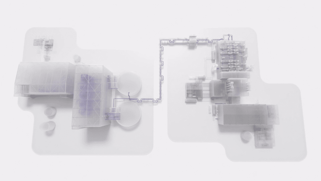
The air flow model of the SCR (Figure 2) starts in a segment of the intake duct upstream of the SCR unit, includes the mixers, turning vanes, and SCR, and ends at an exit plane in a segment of the discharge duct downstream of the SCR. The CFD model included portions of the intake duct and discharge duct to provide a more accurate CFD model to analyze the anticipated conditions within the SCR unit and optimize the ammonia to NOx ratio at the catalyst.
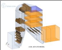
Boundary conditions are very important, and Wood recommends commencing the model study as far upstream in the process as possible in order to provide accurate modeling but also to take advantage of the ductwork geometry. On a recent refinery project (Figure 3), the SCR ammonia injection grid was designed in such a way as to negate the use of turbulent mixing devices and take advantage of the existing ductwork geometry and still maintain sufficient gas distributions. Turbulent mixing devices, although often required, add complexity and pressure drop to the system and is desirable to exclude, if possible.
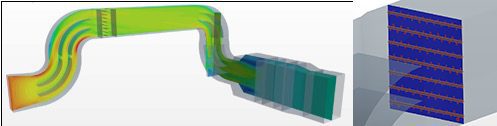
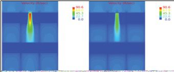
CFD modeling can help evaluate potential operational issues, such as those that might occur due to the physical gaps between catalyst modules. The CFD images in Figure 4 illustrate the high-velocity zones caused by a 1-inch by 1-inch gap between catalyst modules. The SCR inlet ductwork flue gas velocity at full load (90 ft/sec) and partial load (61 ft/sec) are shown on the left and right images, respectively. Such localized spikes can lead to poor performance, accelerated catalyst deactivation, and increased maintenance costs. CFD models are run at full and minimum loads to ensure proper distribution across the entire operating range.
Coupling CFD modeling with analysis by SCR experts also allows for increased flexibility. In cases where existing systems are limited on pressure drop, SCR experts can weigh the benefits of non-ideal flow distribution against catalyst selection. The result will provide the best fit for the application.
Retrofit for Best Fit
SCR systems for new power plants, petroleum refineries, and industrial facilities can be readily optimized since design decisions are not initially constrained. SCR upgrades at existing facilities, conversely, are inherently unique. These “retrofit” cases usually require a high degree of customization during planning and execution.
The location of existing equipment and available space, for example, are key parameters in assessing the constructability of retrofit equipment. 3D models offer insight into the benefits of modular versus site-erected construction. Modularization enables larger pieces of equipment to be handled since assembly occurs in fabrication shops or at grade versus working at the final equipment elevations. This results in construction time savings and improved safety since assembly occurs under more controlled conditions.
Some of the challenges encountered in retrofit installations include congested work areas, limited space for heavy-lift cranes, and insufficient space onsite for module construction and laydown. For example, a complex refinery retrofit project undertaken by Wood required fabrication and installation of a custom-designed SCR inlet flue in an alley space only 12 feet across. A detailed 3D model including the existing equipment and the new SCR equipment was utilized to ensure the erection clearances were sufficient for installation.
Retrofit projects will likely face additional challenges associated with the jobsite. These include soil conditions, seismic and wind requirements, and tie-in outage timing and duration. Also, in the design phase of the retrofit project, the impact of the new equipment on pressure drop and utilization of existing fan capacity must be assessed. Prior familiarity with the potential range of issues encountered during retrofit projects can significantly benefit the project owner.
The Wood Edge
In supplying more than 130 SCR systems globally for a full complement of utility boilers, industrial process heaters, boilers, furnaces, and combustion turbines, Wood has applied and refined design tools and principles to meet or exceed NOx reduction targets while addressing complex retrofit challenges. The Korean SCR installation achieved NOx reduction below the plant’s mass limits and maintained ammonia slip at less than 3 ppm. A recent installation at a California refinery demonstrated 95+% NOx removal with NOx emissions of 3 ppm and ammonia slip less than 1 ppmv at 3% O2.
Completing an SCR system on time and within budget requires a coordinated effort among design, procurement, and construction. While facility owners may have expertise in some elements related to SCR design and operation, engaging a full-service SCR supplier can provide a single point of responsibility for the system including performance guarantees. This approach reduces the overall project risk and cost.
—This article was developed by Lance Meeker of Wood in cooperation with Krishnan & Associates Inc., a specialized energy industry marketing consulting firm.