In a 2023 report, McKinsey & Company projected 35 GW of new power will be needed for data centers in the U.S. by 2030. This forecast doubled the required power consumption from data servers, up from 17 GW in 2022. The explosive growth in data center infrastructure driven by investments in artificial intelligence (AI) is facing a power scarcity. Consequently, these projects are opting for off-grid energy sources or being mandated to “bring power.”
Data center developers are increasingly relying on gas turbines to fill the gap in energy supply as they work on longer-term solutions like nuclear power or grid transmission. While waiting times for new gas turbines are increasing (18 to 24 months), developers have taken novel approaches including mixing turbines from different turbine manufacturers and using refurbished units along with new ones.
Data Center Orders for SCRs
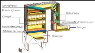
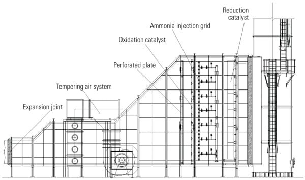
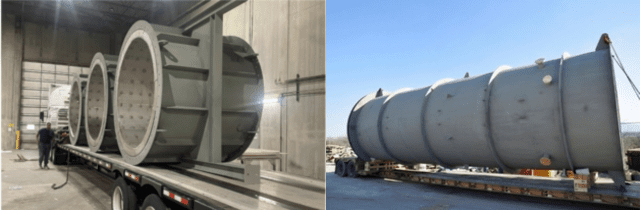
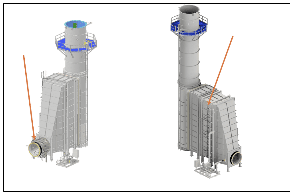
EnergyLink International has recently received orders for 56 selective catalytic reduction (SCR) units and stacks, with many more immediately pending. These SCRs are needed to remove NOx (NO and NO2, collectively nitrogen oxides), CO (carbon monoxide) and VOCs (volatile organic compounds) from exhaust gas streams of turbines that are powering data centers. All orders were for EnergyLink’s Direct Injection SCR—a new technology that cleans the hot exhaust gases more efficiently and at less cost than conventional SCRs, while simultaneously lowering noise (Figure 1). Orders were also for SCRs to limit emissions from a range of turbines: LM2500, T130, and T350.
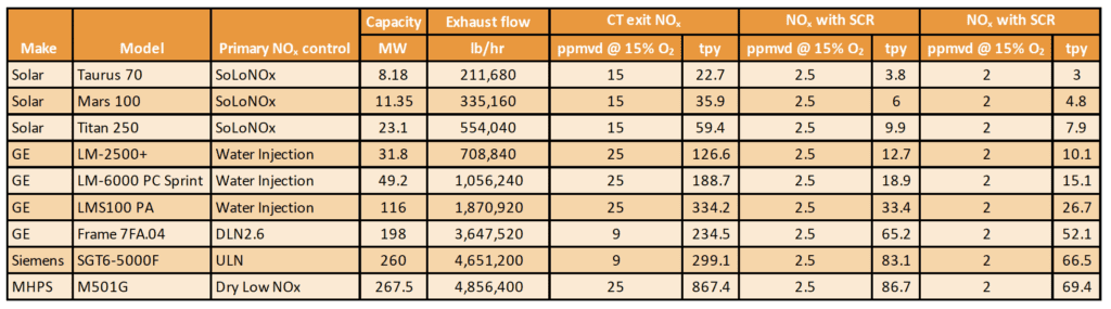
Gas turbine exhaust emissions must meet increasingly narrower limits since the introduction of the Clean Air Act (CAA) in 1970. Today, best available control technology (BACT) limits are 2.0 ppmvd (parts per million by volume, dry) for NOx, ammonia slip, and VOCs, and 6.0 ppmvd for CO. Not all counties must meet BACT standards if air quality is cleaner than the National Ambient Air Quality Standards (NAAQS). In Texas, for example, exhaust emissions adhere to limits of 2.5 ppmvd for NOx and 5.0 ppmvd for ammonia slip (see sidebar). While gas turbine manufacturers use NOx reduction technologies, such as water injection and dry low NOx, turbines burning natural gas are still unable to achieve less than 9 ppmvd to 25 ppmvd, depending on the turbine model (Table 1). The level of NOx increases when diesel or oil fuel is burned.

In This Issue
Full issue
Understanding SCR TerminologyAmmonia Slip: An SCR uses ammonia as a reducing agent in the process of controlling NOx emissions from gas turbines. The portion of the unreacted ammonia passing through the catalyst and emitted out of the exhaust stack is called “ammonia slip.” NOx: NOx is the collective term for the nitrogen oxides, NO and NO2, which are significant components of harmful air pollution, and ground-level ozone formation and acid rain. CO: Carbon monoxide (CO) is a colorless, odorless gas. It results from the incomplete combustion of carbon-containing fuels such as natural gas. VOCs: Volatile organic compounds (VOCs) emissions are the total hydrocarbon (THC) emissions, or unburned hydrocarbons (UHC), excluding methane and ethane. Organic hazardous air pollutants (HAPs) are mostly categorized with VOCs. HAP emissions are very low for gas turbines. Formaldehyde is the primary HAP. PM: PM stands for particulate matter (particle pollution)—the term for a mixture of solid particles and liquid droplets in the air. PM10 and PM2.5 (particles with diameters that are 10.0 and 2.5 micrometers or smaller, respectively) have legislated limits. ppmvd @ 15% O2: This refers to parts per million by volume, dry and corrected to 15% oxygen (O2) or 10 g/kWh. Regulations for specific gas concentrations in the exhaust gas stream are promulgated as if they were diluted by enough air so that the O2 level in the gas stream is 15%. % Root-Mean-Square or % RMS: This is a metric that quantifies the variability in the inlet ammonia-to-NOx distribution, with a lower % RMS indicating a more uniform distribution. |
Hot Selective Catalytic Reduction (SCR) Explained
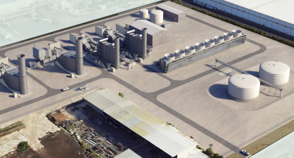
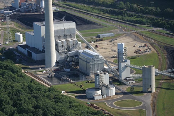
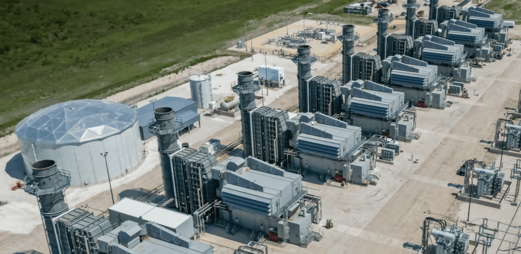
EnergyLink International specializes in “hot” SCR systems, which are SCRs integrated with gas turbines used in simple cycle units. All 56 of EnergyLink’s Direct Injection orders will be baseloaded simple cycle combustion turbines running 24/7 to meet data center electricity consumption requirements (Figure 2). These systems, designed for maximum efficiency, face unique challenges due to the exhaust streams’ extremely high temperatures, and aggressive turbulence and velocities.
The optimal temperature for catalyst bed performance is between 700F and 800F. Recent catalyst formulations can extend the temperature up to 900F or more. For smaller turbines, such as aeroderivative turbines, exhaust gas reaches 800F and 900F. Exhaust temperatures for larger frame turbines can range from 1,000F to 1,247F. When the exhaust gas temperature exceeds 900F, the gas stream must be cooled with tempering air fans to achieve a temperature conducive to catalyst performance.
EnergyLink’s Innovative Direct Injection System
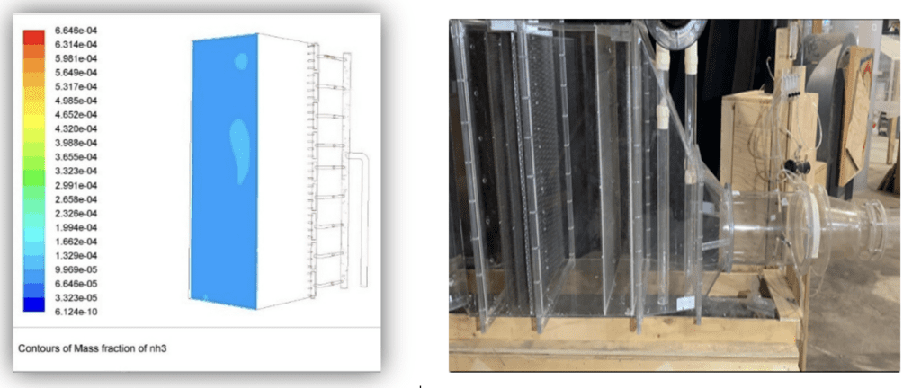
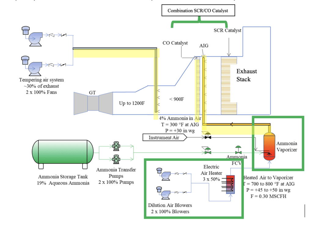
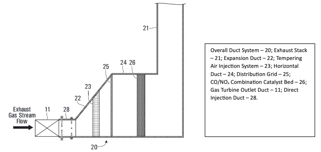
EnergyLink International’s new SCR system introduces ammonia in liquid form to the hot exhaust gas stream in a duct right behind the gas turbine—termed Direct Injection (DI) duct or Direct Ammonia Injection (DAI) duct (Figure 3). This technology was tested by EnergyLink using computational fluid dynamics (CFD) modeling, followed by physical flow modeling. EnergyLink’s engineering team posited that both CFD and physical flow modeling would accurately predict emissions levels from a full-scale SCR unit. The objectives for the development of Direct Injection were to deliver a more effective catalyst system that would reduce costs (capital, installation, and operational) and cut plant parasitic loads caused by the SCR and its auxiliary systems.
EnergyLink partnered with ProEnergy Services to install a full-sized SCR test system behind an operating ProEnergy LM6000PC gas turbine at its Braes Bayou power plant in Texas. This SCR test rig was the first to deploy the new Direct Injection technology to achieve NOx limits of 2.5 ppm or lower, and represents among the first multi-function catalyst applications. The successful results of the runs and tests, which validate the system’s reliability, form the basis of EnergyLink’s patent-pending Direct Injection SCR system.
Paul DiMascio, Chief Engineer at ProEnergy Services, noted, “The brilliant idea of relocating the point of injection right behind the turbine takes advantage of the normal swirl and turbulence of hot exhaust to vaporize and mix the ammonia molecules for better reaction with molecules of NOx and CO.”
He further stated, “Direct injection of water plus liquid ammonia removes the need for a vaporization skid with its dilution air blowers, heaters, and the vaporizer with ducts. It also relocates the injection point farther upstream and closer to the turbine in a much smaller duct. This reduces the size of the injection grid, the number of injectors, and the piping quite a lot, as well as the overall length of the SCR in front of the catalyst. The smaller footprint reduces foundation costs and makes the entire plant smaller, so less acreage [is needed] for it. Direct injection will also reduce maintenance costs because that immense ammonia injection grid gets markedly smaller and cheaper to maintain.”
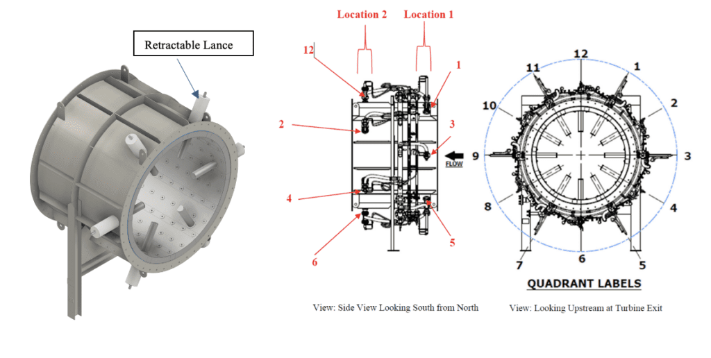
EnergyLink’s Direct Injection method uses multiple, retractable injection lances and nozzles to introduce liquid ammonia into the hot exhaust gas stream in a Direct Injection duct located immediately after the gas turbine exit. The Direct Injection duct is the same diameter as the exhaust diffuser. “That’s about six feet in diameter,” DiMascio said, “so the ammonia injection grid is reduced in area to cover only these six feet instead of the immense area of the Ammonia Injection Grid (AIG) duct,” which is located farther downstream in a conventional SCR. One set of multiple proprietary injection lances with nozzles circle the Direct Injection duct. During testing (Figure 4), EnergyLink performed tuning by adjusting the number of lances and locations to ensure the amount and distribution of ammonia was optimized.
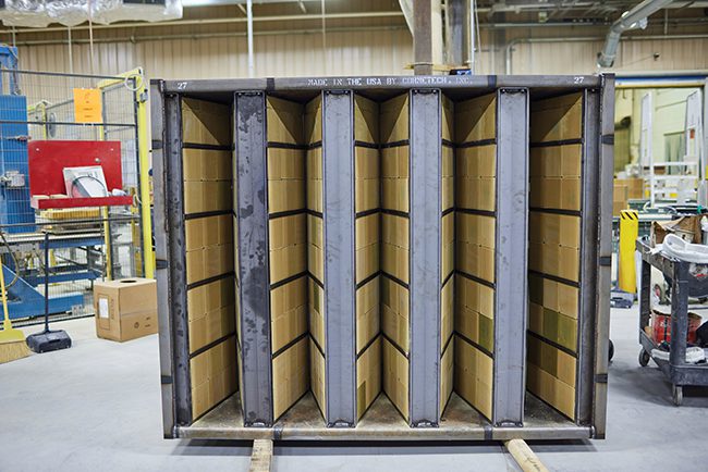
For the test rig, EnergyLink used a CORMETECH METEOR Multi-Emission Catalyst that removes NOx, CO, and VOCs within one catalyst layer, replacing the two catalyst beds in conventional SCR systems. According to the catalyst supplier, EnergyLink’s test rig application represented “one of the first deployments of that catalyst type on a hot SCR.”
Testing Details
EnergyLink validated its new Direct Injection SCR using four test methods. These were:
- Multi-point traverse testing downstream of the SCR catalyst for the conventional and Direct Injection SCR systems at differing injection configurations and operating loads.
- Computational fluid dynamics analysis (Figure 5).
- Physical flow modeling (Figure 5).
- Continuous emissions monitoring system (CEMS) data output.
A traverse test using the conventional AIG with the gas turbine at baseload (47 MW) established a baseline NOx, CO, O2, ammonia, and temperature profile to compare to the same profile from EnergyLink’s Direct Injection system. EnergyLink’s testing engineers also measured at the stack exit and for partial loads, adjusting ammonia flows and Direct Injection lance positions accordingly to optimize the balance of ammonia-to-NOx.
EnergyLink gathered data from the Conventional AIG System as a baseline, followed by data from the Direct Injection SCR under full load (47 MW), two-thirds load (32 MW), and 50% load (25 MW). Because maximum exhaust flow and the shortest residence time within the catalyst bed occurs during full-load conditions, full load typically governs catalyst bed design. Table 2 shows the test results of physical flow modeling compared to the field traverse tests while the LM6000 gas turbine operated at full load.
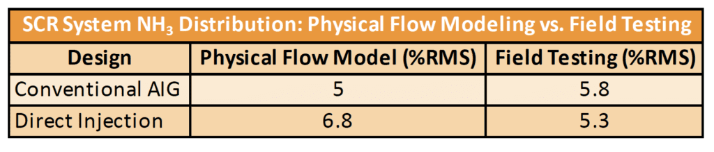
“Direct Injection was predicted by models to be as good as the conventional injection grid in uniformity of mixing (calculated as %Root-Mean-Square),” ProEnergy’s DiMascio noted. “The Braes Bayou plant test showed us it is nearly 10% more uniformly distributed than the conventional injection grid (5.8 %RMS versus 5.3 %RMS) and over 20% better than the models predicted (6.8 %RMS vs. 5.3 %RMS).” Conventional SCR systems, in contrast, register %RMS of 10.0% or higher.
CFD and physical flow modeling of all smaller gas turbine models confirmed that EnergyLink’s Direct Injection SCR system performs as well as or better than the conventional AIG system. DiMascio added, “Direct Injection also gave us 5% lower NOx going out of the stack. This gives us more margin to the current limits, and if demonstrated consistently, it may help us lower the BACT threshold.”
For larger gas turbines, the velocity of the gas turbine exhaust is higher than tested and provides even more turbulent mixing velocities, so lower ammonia-to-NOx ratio %RMS values are expected with correspondingly higher NOx removal levels as modeled. EnergyLink’s testing concluded that its Direct Injection designs apply to all gas turbine models with equivalent ammonia distribution, and therefore NOx removal and ammonia slip, as a conventional AIG system.
Benefits of EnergyLink’s Direct Injection System
Cost Savings. In EnergyLink’s Direct Injection system, components such as the reducing agent vaporization system heaters, blowers, ducting, injection grid, and associated pipes and valves are unnecessary. ProEnergy’s DiMascio explained, “EnergyLink’s DI system reduces costs primarily by eliminating the vaporization skid and by reducing the size of the ammonia injection grid. [Also reduced is] the stainless-steel piping to cover the catalyst uniformly [and that] is a lot of expensive material and welding.” Reducing these components of the SCR system results in a material reduction of 10% to 20% in capital cost (Figure 6).
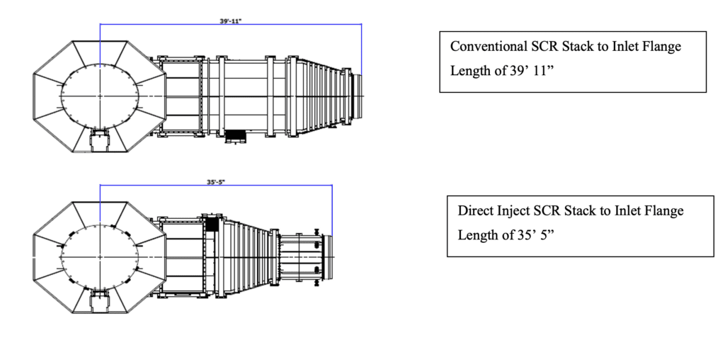
Reduced Footprint. DiMascio continued, “As you know the SCR catalyst is very large in area to slow the exhaust and give NOx time to react with the ammonia. [In a conventional SCR], the ammonia injection grid (AIG) must be the same huge area with very fine spacing of the nozzles to distribute ammonia uniformly over the catalyst. [EnergyLink’s DI system] reduces the overall length of the SCR in front of the catalyst because the ammonia is more uniformly mixed with the exhaust so the whole structure can be shortened—saving on lots of stainless and structural steel [Figure 7].”
Precise, Adjustable Injection. One of the features of EnergyLink’s Direct Injection system is the ability to inject liquid ammonia at multiple locations and various radial distances in the highly turbulent circular inlet (or Direct Injection duct) to achieve NOx and CO reduction comparable to, or better than, a conventional SCR system. EnergyLink’s Direct Injection system (Figure 8) replaces the ammonia injection grid and its many valves and control devices with a pared-down system of injection lances and custom-designed nozzles that keep the ammonia as a liquid for proper nozzle atomization and are easily adjustable in depth and position to obtain the best % RMS ammonia-to-NOx distribution at the catalyst.
Reduced Installation and Operating Costs. Lowering the complexity of an SCR by eliminating components significantly lowers installation costs and time. In EnergyLink’s Direct Injection design, the ducting footprint is noticeably contracted with fewer duct sections, smaller foundations, and fewer gaskets, flanges, base plates, and anchor bolts. This smaller catalyst system provides shipping and transportation cost savings as well. Without a large ammonia vaporization fan, parasitic loads and operating costs are also reduced.
Equivalent to Better NOx Reduction. EnergyLink continues to improve the performance of its Direct Injection system. First, fine-tuning the number and position of the Direct Injection lances and nozzles has helped optimize ammonia flow and improve the balance of ammonia-to-NOx—so much so that the ammonia-to-NOx ratio is 10% better than a conventional SCR and NOx stack levels were 5.0% lower.
Broad Application. EnergyLink also verified that its Direct Injection system can be applied to all aeroderivative gas turbine models. The company has tested its Direct Injection design for various gas turbines with differing exhaust velocities using one-eighth-scale physical flow models and computational fluid dynamics.
Good Return on Investment
The future of SCR technology for simple cycle gas turbines is EnergyLink’s Direct Injection based on recent orders received from data center customers. “I sincerely hope new plants adopt this technology because it reduces capital expense a lot and reduces operating expenses a smaller percentage. That lowers the cost of electricity and helps everyone!” said DiMascio. “The smaller footprint reduces foundation cost and makes the entire plant smaller so you need less acreage for it. Direct Injection will also reduce maintenance costs because that immense ammonia injection grid gets markedly smaller and cheaper to maintain. As plants with existing AIGs age, the maintenance costs increase and there will come a time when you could install a much smaller grid close to the turbine, eliminate an expensive skid, and get a good return on your investment.”
—POWER edited this content, which was contributed by EnergyLink International.