Prior to placing newly installed natural gas piping and valves in service, systems must be properly cleaned to remove potentially damaging foreign material that is inherently left behind during construction. The process is more complicated than it sounds, requiring accurate cleaning force calculations and detailed sequencing steps to ensure all debris is removed. Here’s how to do it right.
Before new fuel gas piping can be connected to a combustion turbine (CT), it must be cleaned by “decompression” gas blows.
The Process
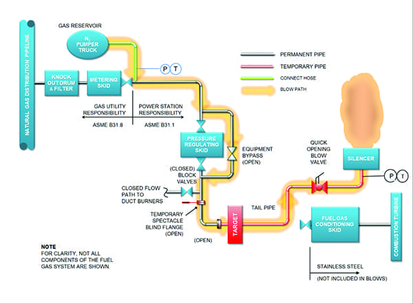
The pipe to be cleaned is connected at one end to a gas reservoir. This can be a tank or upstream section of clean empty piping. At the other end, a temporary exhaust pipe and valve is installed. The reservoir is pressurized to less than half the design pressure. When the blow valve is rapidly opened, the pressurized gas violently rushes through the piping and out the exhaust pipe (Figure 1).
 |
|
1. A typical configuration of gas blow piping components is shown here. Courtesy: Michael F. Czyszczewski, PE |
As the gas moves through the pipe, debris and liquids are picked up and blown out. When the reservoir depressurizes to a level where no more cleaning is effectively taking place, the valve is closed. The process is then repeated over and over (10 to as many as 100 times) until the pipe is judged clean.
If a large enough compressor is available, small diameter (less than 4 inch) piping or small lengths of pipe could alternatively be cleaned by a “continuous blow” technique. This could speed up the process by eliminating the pressurization cycles.
What Gas Should You Use?
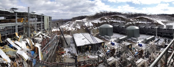
The first choice for cleaning gas has been to use the operating gas. However, after a deadly 2010 explosion occurred while using natural gas, the industry re-evaluated this practice. The Chemical Safety Board (CSB) investigating the accident recommended that natural gas not be used for pipe cleaning. The CSB also urged the governing code and standard organizations to ban the use of flammable gas and to publish guidelines for cleaning with alternative gases.
In response, the National Fire Protection Association (NFPA) issued NFPA 56 “Standard for Fire and Explosion Prevention During Cleaning and Purging of Flammable Gas Piping Systems” in provisional form in 2011, and final form in 2013. This standard prohibits the use of flammable gas for pipe cleaning where the system design pressure exceeds 125 psig. In 2011, the Electric Power Research Institute (EPRI) released “Guidelines for Fuel Gas Line Cleaning with Compressed Air or Nitrogen.” These alternative gases compare as follows:
-
- Air. The air must be clean, dry, and oil-free. Gas blows will probably require larger pressures and flows than are available from the station instrument air compressors. If necessary, larger or multiple compressors could be rented to get the pressures and flow rates needed. Accessories such as an air receiver, relief valves, regulators, and air dryers may also be required.
- Nitrogen. Chemically inert nitrogen is commonly used to purge and provide blanketing corrosion protection for fuel gas equipment. Nitrogen is nonflammable, nonexplosive, dry, and free from oil. Nitrogen does pose a potential asphyxiation safety risk, which must be addressed if used. The gas can be produced on-site in large volumes (from 3,000 standard cubic feet per minute [scfm] to 15,000 scfm) and very high pressures (up to 15,000 psig) by rented pumper trucks originally developed for use in the oil and gas industry. These trucks contain the instrumentation, storage tanks, pumps, liquid nitrogen, vaporizers, safety valves, and other equipment required to supply pressurized gas.
The economics of air and nitrogen could be very similar. The gas you choose must be based on your project-specific requirements.
In its 2016 release, the American Society of Mechanical Engineers (ASME) B31.1 piping code clarified that it did not provide guidance for pipe cleaning methods, but added in its 2018 release that fuel gas pipe cleaning may be subject to the requirements of NFPA 56. NFPA standards are often adopted as federal, state, or local law.
When Is the Pipe Clean?
A polished metal plate known as a “target” is inserted in the gas path where it will be struck by debris particles during the gas blows. Pipe cleanliness is based on the number and size of particle strikes allowed by the CT manufacturer. Blows continue until the examination of two consecutive plates show no more scoring than allowed by the acceptance criteria.
The target should be installed on the temporary exhaust “tail pipe,” as close to the segment of pipe being cleaned as possible to prevent false target readings from debris originating within the temporary pipe. It should be located away from flow disturbances created by elbows and tees, and not be installed at the pipe exit, where there should be a shock wave. The target should be as small as practical to minimize pressure drop. Hard metal plates will show fewer impacts, therefore, the material, design, and location of the target must be agreed to by the owner and CT manufacturer.
The majority of cleaning takes place during the initial round of gas blows. As cleaning progresses, the color of the discharge plume will change from rust orange to clear. Only after significant cleaning has taken place, should the target be inserted.
What Piping Is Cleaned by Gas Blows?
Manufacturers will identify how the gas inlet piping to their equipment should be cleaned. Gas blows are primarily performed on the fuel gas supply piping from the outlet of the gas service meter to the isolation valve inlets at the CT. If stainless steel piping is used downstream of the fuel gas conditioning skid, it can instead be visually inspected using a borescope. If debris is found, the stainless pipe should be blast or brush cleaned, as conditions require.
If the gas equipment piping does not have a specified cleanliness criterion, it may still be cleaned using gas blows. Non-targeted “service blows” are used, and cleaning continues until the exhaust plume turns clear. Fuel gas piping to heat recovery steam generator duct burners is one example. Other secondary systems, such as the gas supply piping to an auxiliary boiler, can instead be chemically cleaned or blast cleaned followed by a service blow.
It may not be practical to do gas blows on some complex piping arrangements. Short hard to reach pipe can instead by cleaned by hydrolazing (high-pressure water blasting).
Identifying Blow Paths
The length of piping that can be cleaned during a gas blow is limited. Flow resistance, and the location of isolation valves and branch connections, will usually require multiple flow paths. Each path will need time and resources to prepare and set up. Identifying the optimum blow paths is critical to having an efficient process and, therefore, requires thoughtful consideration to minimize the number of blows needed.
The process of identifying the blow paths is called “sectioning.” A piping and instrumentation diagram (P&ID) should be studied and marked to show the direction and path for each planned blow. This diagram should show the location of the proposed gas source, target plate, blow valve, block valves, instrument valves, tail pipe, and all temporary connections to the permanent pipe.
The diagram should also identify any equipment skids, flow nozzles, orifice plates, and thermal wells that should be removed, replaced with spool pieces, or bypassed to prevent them from being damaged or to eliminate the pressure drop they would cause during gas blows. If a valve cannot be removed, it should be fully open during the blows and occasionally cycled closed and open between blows to shake lose any particulates that may have gotten caught in the valve. The following is some advice for defining blow paths:
- A path should always start at a gas source rated for the expected blow pressures, and with sufficient volume to accommodate reasonable blow times. This source can be a nitrogen pumper truck, isolatable section of upstream pipe already cleaned, or a rented pressure vessel.
- A path should end at a temporary tail pipe outlet. For some blow paths, it may be necessary to relocate the tail pipe. Alternatively, additional tail pipes could be used.
- Long blow paths have high flow resistance and should be avoided. High resistance will require a higher reservoir pressure and use more blow gas.
- A dirty blow path should not introduce flow into a section of pipe cleaned in an earlier blow.
- Blow paths can be run in the reverse of the normal flow direction. This is sometimes necessary when the reservoir volume upstream of the pipe being cleaned is inadequate, but there is sufficient downstream volume that could be used.
- It must be possible to isolate the flow path. If necessary, temporary valves or spectacle flanges can be installed to block a branch line. Dead-ended (stagnant) pipe segments should be avoided, as they can trap debris.
The Blow Valve
The blow valve is critical to successful cleaning. When closed, the blow valve is used as a stop valve to allow the upstream piping and reservoir to be pressurized. When opened, it initiates the gas blow cleaning process. Most importantly, the valve must be able to open quickly. A faster valve will allow more cleaning gas to scour the inside of the pipe at maximum velocity. A quarter-turn ball valve or knife gate valve that opens in 0.5 to 1 second (or better) is a good choice. An automatic operator is preferred for safety reasons.
The closer the valve is to the tail pipe; the more volume will be available upstream for pressurization. More volume gives greater stored energy and longer blows. Alternatively, locating the valve upstream of the piping being cleaned will provide an additional cleaning benefit when the valve pops open and the pressurized gas impacts the dirty pipe. However, most importantly, the valve should be installed away from flow disruptions, and if a manual valve is used, it should be in an accessible and safe location.
Because the blow valve will be subjected to high stresses, loads, and debris, it can be easily damaged. It’s therefore considered good insurance to have a spare.
Rupture disks are sometimes used instead of a blow valve. They are disposable and open very quickly. However, because they must be replaced after each blow and are manufactured to a single predefined burst pressure, they may not be suitable when many gas blows or starting pressures are needed.
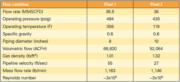
Cleaning Calculations
The principle behind gas blow cleaning is to create high gas velocities and drag forces, which will shear debris off the pipe interior walls. This cleaning force (CF) is defined as follows:
CF = (mB2 x vB) / (2 x gc x A)
where mB is the mass flow rate of the blow gas during cleaning, vB is the specific volume of the blow gas during cleaning, gc is the gravitational constant, and A is the area at the tail pipe exit. (All variables in equations referenced in this article use customary U.S. units, such as ft, sec., lb, psia, and F, unless otherwise stated.) CF during the gas blow must be greater than the maximum CF during operation for effective cleaning to take place. In other words, the ratio of cleaning to operating CF, known as the cleaning force ratio (CFR), must be greater than 1.0, as calculated in the following equation:
CFR = CFB / CFM ≥ 1
where CFB is the cleaning force of the blow and CFM is the maximum cleaning force during operation. Assuring CFRs are greater than 1.0 is the fundamental criteria upon which the gas blow starting pressures are based. Experience has shown that drag forces from a CFR greater than or equal to 1.2 will provide acceptable results. Higher CFRs do not show significantly faster cleaning and are not recommended because more gas is exhausted. However, a higher CFR margin should be used if required by the equipment manufacturer.
CFR increases as you move downstream in a constant diameter pipe, therefore, the majority of the pipe will see CFR’s many times greater than 1.0. Also, the calculations do not take credit for the dynamic shock that occurs when the blow valve is suddenly opened. Because of this conservatism, a minimum CFR of 1.0 is considered reasonable and sufficient for service blows.
To calculate CFR, the mass flow and specific volume is needed along the entire blow path. Sonic and subsonic velocities, choked flow, and density changes occur, which make the calculations difficult. Fortunately, compressible fluid flow software greatly simplifies the effort.
First, construct a software model of the system in its normal operating configuration. Runs of each operating mode are then used to find the largest values corresponding to the terms in the denominator of the CFR equation.
Next, modify the model to include any configuration changes that will be made for cleaning. All temporary pipes, bypasses, the tail pipe, blow valve, and blow path block valves should be added.
The objective is to use the model to find the blow gas reservoir starting and ending pressures that will result in acceptable CFR values throughout the length of pipe being cleaned. This is done by a trial and error process in which different pressures are tested, and the mass flow and specific volume results are imported into a spreadsheet that calculates the CFRs. The following is some advice for determining starting pressures:
- As the pipe depressurizes (is blown down), gas velocity will decrease. When the source pressure drops to a point where the CFRs are below 1.0, the gas blow can be terminated. By not completely depressurizing, the recycle time and quantity of gas used can be minimized. However, use some judgement. If the blow down times are very short (less than 10 seconds), complete depressurization will allow more time to eject the debris.
- Increasing the gas mass flow rate or specific volume will increase the CFR. Mass flow rate can be increased by increasing reservoir pressure. Specific volume can be increased by decreasing pipe pressure or increasing the temperature.
- When gas flows through a pipe, the pressure drops along the path due to friction. The pressure drop causes the gas specific volume and velocity to increase. If the sonic velocity is reached, a shockwave forms. The velocity will no longer increase beyond the shockwave and the flow is considered “choked.” Sonic choking can occur at locations where the pipe diameter suddenly increases, at the pipe exit, and at constrictions such as a reduced bore valve. Ideally, sonic choking should only occur at the pipe exit and not inside the pipe, where it could cause severe pipe vibrations.
- Increasing the tail pipe diameter will increase the CFR. However, the tail pipe diameter should be no larger than that of the piping to which it connects to avoid creating an internal choke point.
Pressure and temperature instrumentation with data recording capability, installed near the gas inlet and outlet, should be used to confirm that acceptable CFRs are being achieved. Use a table or chart of gas properties to get the specific volume based on measured pressure and temperature. Studies have shown that the most reliable method of determining the mass flow rate (mB) is to base it on a calculation of sonic velocity (c) at the exit.
mB = A x c / vB
where c is √(k x gC x 144 x PE x vB), k is the ratio of specific heat (about 1.4 for air and nitrogen), and PE is the pressure at the gas exit.
Noise Control
Gas blows are loud. In fact, sonic shock waves may be visible in the gas plume exiting the tail pipe. Hearing protection will be required for anyone working nearby.
Sound pressure level (SPL) indicates the intensity of the sound at a given point with respect to a reference level. Measurements are usually expressed in dB(A) units where the “A” indicates an adjustment for the frequency sensitivity of human hearing. Based on an Occupational Safety and Health Administration (OSHA) noise limit of 90 dB(A), a reduction to less than 85 dB(A) at a distance of 3 feet is recommended. SPL can be estimated with the following expression derived from American Petroleum Institute (API) Standard 521:
SPL ≅ 20 log (dE / 1000) – 10 log (vB) + 80 log [(4 x vB x mB) / (π x dE2)] – 10 log (2 x π x r2) – 22.232
where dE is the tail pipe gas exit inner diameter and r is the distance from pipe exit. If the plant is near a residential area, a silencer will be necessary. When specifying a silencer, pressure loss at the maximum flow rate should be restricted to no more than about 1 psid. A high flow resistance will result in higher blow pressures and more blow gas being used.
Time and Mass Calculations
When depressurization begins, the pressure differential between the reservoir and the atmosphere is high, and the exit flow is at sonic velocity. As the differential decreases, the exit velocity remains constant until a critical pressure is reached and it becomes subsonic. As the reservoir pressure is reduced further, the volumetric flow and mass flow drop until the differential pressure reaches zero. Blowdown time (tBD) can be estimated with the following empirical expression recommended by the American Gas Association (AGA):
tBD ≅ (0.1225 x P1 0.333 x SG0.5 x V x Fc) / dE2
where P1 is the gas reservoir starting pressure, SG is the specific gravity relative to air (1.0 for air and approximately 1.0 for nitrogen), V is the storage volume under pressure (including tank, reservoir, and piping), and FC is the choke factor (1 for an ideal exit to 1.8 and higher for a typical gate valve). Ensure the blowdown time is sufficiently greater than the blow valve opening time and the reservoir is not pressurized above the rated pressure capability of the components.
A positive displacement compressor will fill the reservoir at a relatively constant flow rate. The time to recharge the reservoir (tCHARGE) can be estimated with the following expression:
tCHARGE ≅ [V x (P2 – P1) x 60] / (Pa x Q)
where P2 is the gas reservoir ending pressure, Pa is atmospheric pressure (14.7 psia), and Q is compressor output capacity for filling the reservoir. To estimate the calendar days needed for cleaning, the number of blows required for each blow path is needed.
Unfortunately, an accurate prediction is nearly impossible. The number can vary from 1 to 100. If there was an emphasis to “build it clean,” fewer blow cycles should be needed. Whatever number is used, it’s going to be a rough estimate, so add margin. Additional time should be added to account for gathering and checking instrumentation data, calculating CFRs, removal and insertion of target plates, and inspecting the target.
Experiencing a shortage of nitrogen during the cleaning process will delay completion. To estimate the quantity of nitrogen required for a gas blow (q GAS), use the following expressions based on the perfect gas laws:
qGAS ≅ (2.7 x SG x P1 x V) / T
where T is the gas temperature in Rankine (F + 459.67), or:
qGAS ≅ V / vB
Pressure Testing
ASME B31.1 covers the design and testing of power plant piping systems. ASME B31.3 is used for industrial piping such as at a refinery or chemical plant. ASME B31.8 applies to gas transportation and distribution piping. The plant owner should identify which codes to use and where they apply.
Prior to performing gas blows, the piping must be pressure (leak) tested. Normally, water is used. However, if permitted by the piping code, pneumatic testing could instead be performed using the cleaning gas. This may be desired in situations where the hydro test water cannot be easily removed, cannot be tolerated in the pipe, or is not sufficiently available.
The applicable piping code describes the process for conducting a pneumatic pressure test. ASME PCC-2 gives a method for determining the distance enveloping the pipe that should be marked off with caution tape and cleared of people. The decision to perform a pneumatic test should not be taken lightly. Pneumatic pipe ruptures occur suddenly, usually without warning; therefore, pneumatic testing is discouraged.
Discharge Force
Much like thrust from a rocket engine, the open discharge will create a static reaction force at the tail pipe exit. Usually an anchor is required to restrain the tail pipe from movement. API RP 520-2 provides the following expression which can be used to estimate the thrust force at the tail pipe exit (F):
F = 9.836 x mM x √{(k x T) / [(k+1) x Mwt ]} + [144 x (PE – Pa) x A]
where mM is the mass flow rate of gas during maximum operation and MWT is the gas molecular weight (about 28.5 for air and nitrogen). When the blow valve suddenly opens, the pipe will be subjected to dynamic loads as the gas starts flowing. The dynamic forces are accounted for by a dynamic load factor (DLF). This factor represents the ratio of the peak stress from a rapidly applied load to the stress that would occur, if applied slowly. DLF ranges from 1.1 to 2.0. Typically, a DLF of 2 is used. If a lower value is desired, see ASME B31.1 for details.
Do the Job Right
In a 2010 CSB-conducted survey on gas blow cleaning, about half of the respondents stated they did not have a technical basis for determining the gas flows and pressures they should use. Without the guidance of supporting calculations, it’s likely that more time and gas will be required for cleaning. An analytical approach to gas blow cleaning will help to ensure that the process proceeds safely and efficiently.
In sports, a blowout is when one team outperforms another by a large margin. When it comes to blowout pipe cleaning, preparing a technical basis for the work will make sure you are on the winning team. ■
—Michael F. Czyszczewski, PE (mczyszczewski@asme.org) is a mechanical engineer with 40 years of experience in the power industry.