It can be a challenge to keep emissions in check while operating dual-fuel reciprocating engine technology during low-load conditions. However, doing so is especially important under California’s strict emissions requirements. The Humboldt Bay Generating Station team did just that by taking a critical look at multiple emissions control systems and identifying several process modifications that improved overall plant performance.
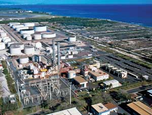
Humboldt Bay Generating Station (HBGS) is a Pacific Gas and Electric (PG&E) owned and operated facility consisting of 10 Wärtsilä W18V50DF A engines. The plant is situated on Humboldt Bay in northern California. Each four-stroke engine is capable of producing 16.7 MW (gross) to provide a combined station net output of 163 MW.
The 10 engines feed two 60-kV local distribution lines and one 115-kV transmission line. Bus-tie breakers located prior to the step-up transformers allow reconfiguring engines to other line resources, as necessary. Each engine is capable of operating between full load and the permit minimum load of 10 MW. The station entered commercial operations in September 2010.
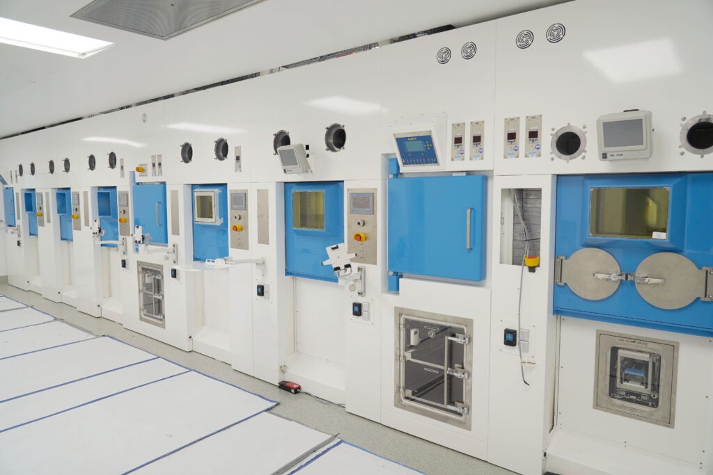
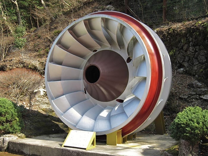
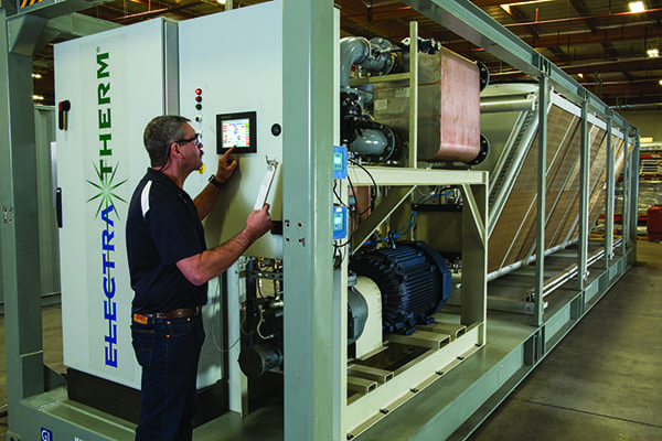
HBGS was constructed to replace an aging gas-fired boiler facility residing on the same property. Dual-fuel type reciprocating engines (Figure 1) were chosen for three main reasons: Humboldt County’s relative remoteness; lack of redundancy in the natural gas supply; and the risk of natural gas curtailment during cold weather. The engines normally operate on natural gas with a small amount of light fuel oil (LFO or diesel fuel). However, during emergencies all engines are capable of operating solely on LFO.
 |
| 1. Reciprocating engines. Humboldt Bay Generating Station (HBGS) has 10 Wärtsilä W18V50DF A dual-fuel type reciprocating engines. Courtesy: HBGS |
How It Works
Burning natural gas in a diesel-cycle engine requires the use of either a spark plug or small amount of LFO to ignite the natural gas. Operating in dual-fuel mode, each engine is required to utilize California Air Resources Board–certified LFO as pilot fuel to ignite the natural gas burned in the cylinder. The natural gas enters the engine with the combustion air on the intake stroke, and pilot fuel is injected just prior to the pistons reaching top dead center on the compression stroke. The fuel ignites during compression.
The pilot fuel needed to ignite the gas is extremely small when compared to the amount of natural gas utilized to generate the electricity. Full-load dual-fuel pilot fuel consumption is approximately three gallons per hour per unit compared to full-load operation diesel fuel consumption of approximately 850 gallons per hour per online unit.
Even though each engine is capable of operating on liquid fuel only, the HBGS air permit only allows 1,000 hours of diesel operation on a rolling annual basis. For example, 10 engines operating at the same time at any load in diesel mode can only operate for 100 hours. In addition, the facility is only allowed to operate an engine in diesel mode for certain conditions listed in the permit, such as during gas curtailments, testing, and routine maintenance tasks that cause common gas supply components to be out of service.
The engine control system allows a seamless transfer to full-diesel operation, if the control system detects combustion anomalies or if gas flow is suddenly interrupted to the engines. Because of the limited amount of diesel-mode operation this article will focus on issues resulting from dual-fuel operation only.
The HBGS air permit was issued to meet the requirements of Title 40 Code of Federal Regulations Part 60, as well as requirements set forth by the Environmental Protection Agency, North Coast Air Quality Management District, and the California Energy Commission. The permit is extensive (43 pages) and addresses many pollutants. However, for purposes of this article only nitrogen oxides (NOx) and carbon monoxide (CO) emission troubleshooting and resolution are addressed.
The dual-fuel NOx emission limit is 6 parts per million (ppm), corrected to 15% oxygen, on a one-hour average, and the CO emission limit is 13 ppm (corrected to 15% oxygen) on a three-hour rolling average. The pilot heat limit, which is 0.8 MMBtu/hr (three-hour rolling average), is also important when discussing NOx and CO limits.
Process Explanation
Combustion air (charge air) enters along both sides of each engine through a turbocharger-driven compressor. A waste gate regulates turbocharger speed to control combustion air (charge air) pressure at approximately 30 psi. High-pressure combustion air exits each turbocharger compressor into charge air coolers to remove heat gained during the compression process. The charge air leaves the charge air cooler and enters a common charge air receiver installed along the upper engine block and situated between the A bank and B bank cylinders.
During operation, 115F charge air and natural gas enter the cylinder on the intake stroke. As mentioned previously, a small amount of pilot fuel is injected during the compression stroke to ignite the natural gas. The combustion gas mixture exhausts into a common exhaust header at approximately 930F.
The combustion gas splits to supply the A bank turbocharger turbine and the B bank turbocharger turbine. As mentioned previously, a single waste gate (air-actuated butterfly valve) regulates the amount of combustion (exhaust) gasses flowing through the A and B bank turbocharger turbines to control the charge air pressure by bypassing combustion gases into the exhaust pipe downstream of the turbocharger. The combustion gas temperature leaving the turbocharger turbines is approximately 820F.
Exhaust from the A bank and B bank turbocharger turbines combines into a single exhaust pipe and 19% aqueous ammonia (NH3) is injected into the exhaust pipe a short distance beyond that point. The combination NH3 and combustion gas mixture flows through a mixing chamber inserted into the approximately 70-inch-diameter pipe about 15 feet prior to multiple rows of catalyst contained within a single housing. The exhaust gas enters the housing at approximately 820F.
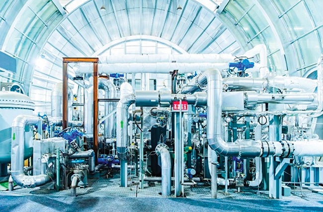
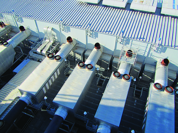
The catalyst (Figure 2) consists of two rows (layers) of selective catalytic reduction (SCR) where raw NOx is destructed. The exhaust gas then flows through one row (layer) of NH3 slip catalyst where the excess NH3 is removed. Immediately following the NH3 slip catalyst one row (layer) of oxidation catalyst destructs the raw CO (Figure 3). At full load the exit temperature is slightly lower than inlet temperature.
 |
| 2. Station catalyst. Flue gases flow through layers of catalyst to reduce unwanted emissions. Courtesy: HBGS |
Significantly, the catalyst installed at HBGS does not follow the conventional catalyst order. Conventional catalyst installation order is oxidation catalyst for CO removal, followed by NH3 injection, followed by SCR catalyst for NOx removal. The benefit of the HBGS installation is no or very low NH3 slip, allowing the facility to be installed in close proximity to population areas with no danger of foul smelling NH3. An additional benefit is the elimination of continuous NH3 slip monitoring.
 |
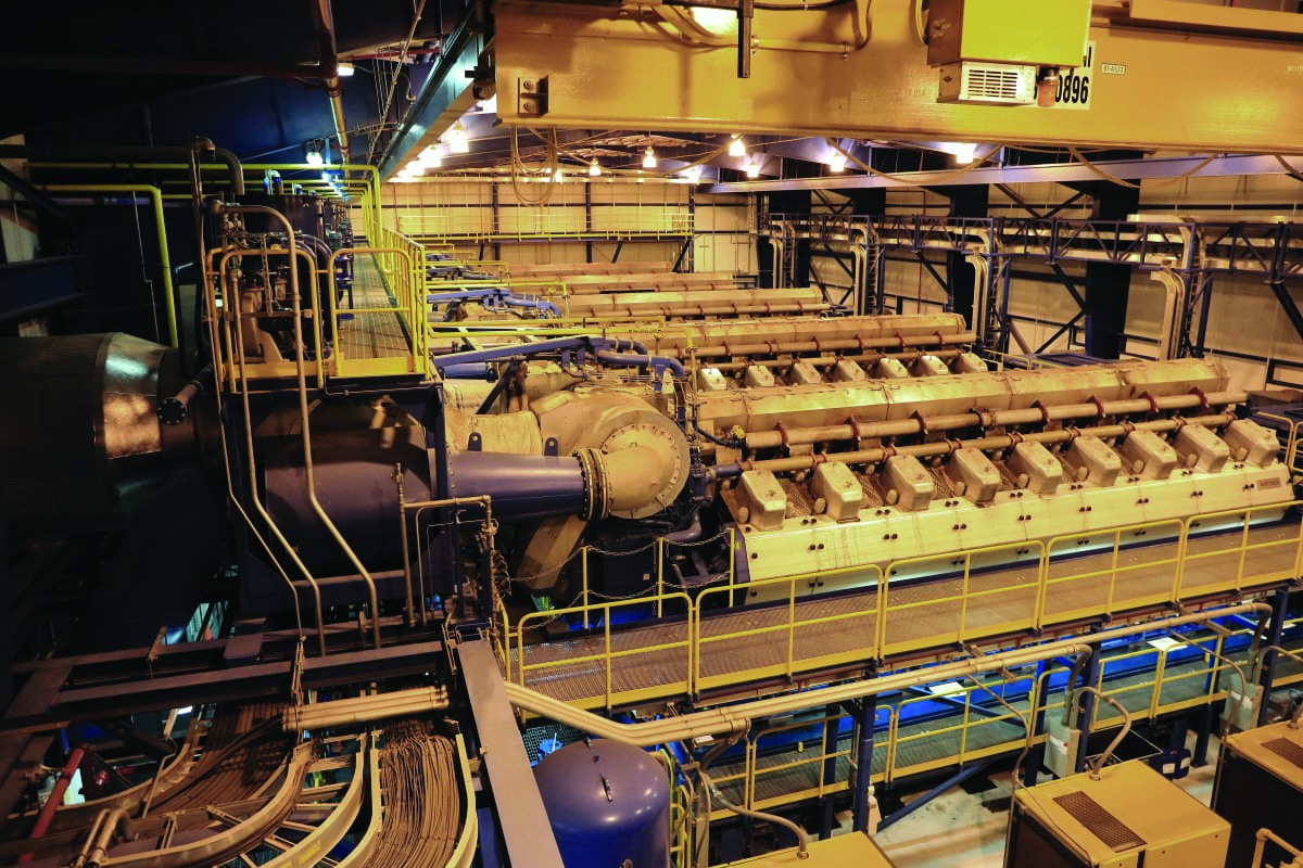
| 3. Emissions control equipment. Inside the ductwork, shown here, HBGS’s catalyst consists of two rows of selective catalytic reduction for NOx destruction, one row of ammonia slip catalyst, and one row of oxidation catalyst for raw CO destruction. Courtesy: HBGS |
Hug Engineering supplied the exhaust catalyst, which consists of two layers of SCR brick, one layer of reduction/oxidation material (ROM, NH3 slip catalyst) brick, and one layer of oxidation catalyst brick. The SCR brick receives the NH3 and raw NOx exhaust gas and creates the reduction reaction resulting in water (H2O) and nitrogen (N) at the catalyst outlet. CO is not reduced in the SCR.
The exhaust gas mixture (H2O, N, CO, and NH3 slip) enters the NH3 slip catalyst brick where the NH3 slip is removed. In the Hug Engineering–supplied ROM brick the NH3 is first oxidized, producing some NOx, and then immediately reduced to convert the produced NOx to H2O and N. Then the exhaust gas mixture (H2O, N, and CO) enters the oxidation catalyst brick where CO is oxidized to produce CO2.
The exhaust catalyst system is equipped with two empty layers, one for the SCR brick, and one for the oxidation brick. As catalyst system performance deteriorates, it is common practice to add an SCR catalyst layer or oxidation catalyst layer to improve performance. It is not possible to add an additional NH3 slip catalyst layer, however. The original equipment manufacturer (OEM) supplied emission control system does not have an open layer to add NH3 slip catalyst because the chemistry involved in the ROM-style NH3 slip catalyst does not support two layers in series.
Precise NH3 injection is critical to the proper operation of the catalyst layers. Insufficient NH3 flow into the SCR layers makes them incapable of destructing the raw NOx to the desired levels. Excessive NH3 flow will not affect the ability of the SCR layer to destruct the NOx; however, it can overwhelm the NH3 slip catalyst. If the over-injected NH3 is greater than the capacity of the NH3 slip catalyst, the excess NH3 flows through the NH3 slip catalyst layer and is oxidized to NOx in the oxidation catalyst layer. If the oxidation catalyst becomes overwhelmed with the increased NOx, CO destruction will be reduced, also resulting in high CO emissions.
Proper NH3 injection is heavily dependent on fine flow control and proper mixing in the exhaust pipe. Each engine utilizes a dedicated NH3 injection system capable of injecting more than 500 liters per hour (l/hr) of 19% aqueous NH3 in full-diesel mode and 20 l/hr to 80 l/hr of 19% aqueous NH3 in dual-fuel mode. The NH3 flow requirement is dependent on raw gas NOx levels from the engine. In other words, the NH3 control system has an approximate turndown ratio of 10:1 when operating in diesel versus dual-fuel mode.
NH3 is supplied to each engine exhaust pipe from a common supply header at 80 psi. A single flow control valve (Figure 4) capable of supporting diesel and dual-fuel operation regulates NH3 to each engine based on a NOx value measured immediately following the two SCR layers.
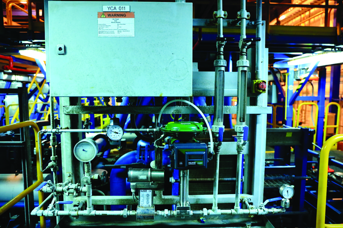 |
| 4. Ammonia (NH3) addition. NH3 injection is controlled by a single flow control valve, which posed problems for the original valve when operating at low loads. Courtesy: HBGS |
Immediately following the single flow control valve, the NH3 injection system splits into two separate streams to supply two NH3 injectors inserted into the engine exhaust pipe (Figure 5). Rotameters installed in the NH3 injection lines provide flow indication to each injector. Needle valves installed downstream of each rotameter provide the ability to equalize flow, as needed. Each injector is supplied atomizing and purge air.
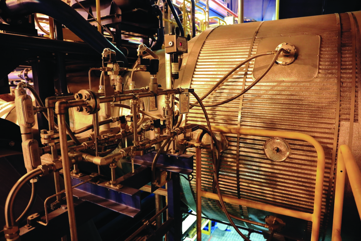 |
| 5. Injection system. HBGS injects a 19% aqueous NH3 solution into the exhaust pipe to control NOx emissions. Courtesy: HBGS |
Challenges
Prior to 2014, HBGS had difficulty operating engines below 14.5 MW, because the pilot heat value would increase to the permit limit (0.8 MMBtu/hr). The engine OEM was brought in to tune the engines, allowing the facility to operate at the minimum permit load of 10 MW.
Wärtsilä technicians were able to tune the engines and achieve pilot heat values below 0.8 MMBtu/hr at minimum load. However, reducing pilot heat values to meet permit requirements caused the CO emissions to increase closer to the permit limit and increased the instances of the engine automatically transferring from dual-fuel operation to diesel operation due to low exhaust temperature from random cylinders.
Although the plant’s permit limits operation below 12.5 MW to 80 hours aggregate per day, the facility began cycling load between full load (16.7 MW) and 10 MW in July 2014. Within a year, emissions from all engines were deteriorating at a rate greater than had been previously experienced. This included engines with lower operating hours. At that time, the engine with the most operating hours had 24,000 hours, while the engine with the least hours was at 6,000.
Plant operators began having trouble keeping NOx and CO within emission limits. The loads at which NOx and CO would increase were somewhat random, but in general, it was more difficult to remain compliant at lower loads than at higher outputs.
Focusing on Improvement
To remedy the trouble, plant staff concentrated on several items.
Ammonia Flow Control. Hug Engineering supplied predictive spreadsheets that indicated the possibility of higher NOx during over-injection situations (Figure 6). As raw NOx levels decreased, plant personnel observed that it was more difficult to maintain compliance with NOx and CO limits. That indicated NH3 over-injection was greater at the low raw NOx levels.
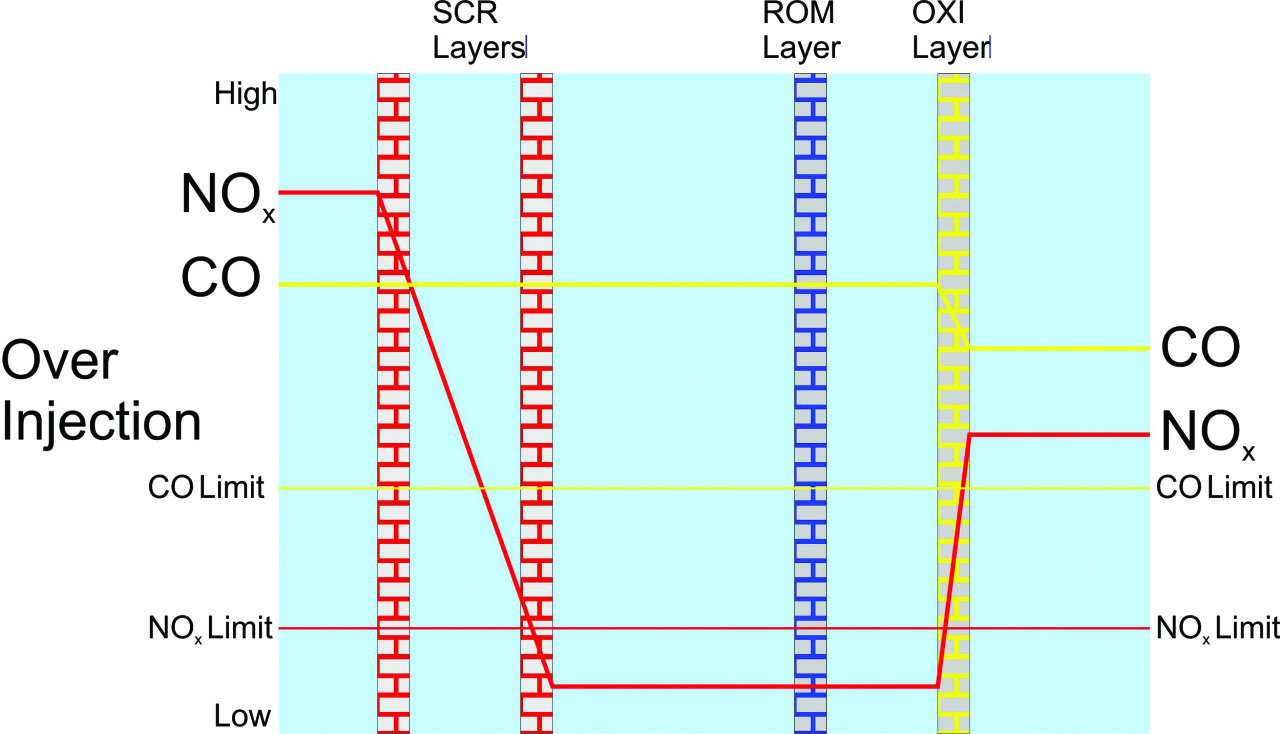 |
| 6. High NOx during over-injection. Over-injection of NH3 resulted in NOx increasing through the oxidation catalyst brick. Courtesy: HBGS |
Plant operators tried manually throttling NH3 supply valves to reduce over-injection, and they were able to reduce NOx and CO emissions significantly (Figure 7). Automatic flow control valves were stroked and tuned without success. The original flow control valve was incapable of turning down enough to control NH3 flow at the low-flow values needed for dual-fuel operation.
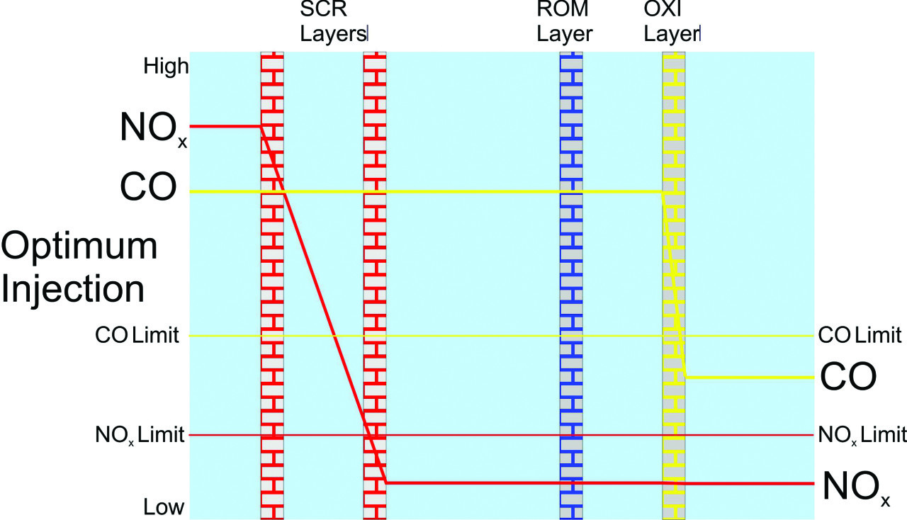 |
| 7. Optimal injection. By manually throttling NH3 supply valves, injection was optimized and NOx remained in check. Courtesy: HBGS |
Plant engineers identified a dual-range flow control valve compatible with the existing NH3 control system. The original NH3 control valve was single stroke with a single valve seat. That required the single valve to control the full range (diesel operation and dual-fuel operation) of NH3 flow.
The new control valve has a variable flow coefficient, which allows fine control at the low flows required when operating at lower loads while in dual-fuel mode while still maintaining the high flow capacity required for diesel operation. Once calibrated, the dual-range flow control valve provided a significant improvement at low loads and reduced NH3 over-injection significantly. By installing the dual-flow control valve the facility avoided the expense of installing a low-flow control system in parallel with the high-flow control system.
The engines continue to operate with some over-injection because the mixing system is sized to handle NH3 flow rates required for diesel operation. The facility continues to explore NH3 atomization and injection options that will provide greater control.
Tuning. Wärtsilä technicians were consulted to tune the engines. Technicians were limited in their ability to “tune out” high NOx or high CO. Tuning an engine to reduce NOx emissions will typically raise CO emissions, and reducing CO emissions will tend to increase NOx emissions. Engines operating close to the emissions limit had limited success with tuning due to the opposing nature of NOx production versus CO production.
A very important tuning goal was to have a steady raw NOx output from an engine. Erratic raw NOx production causes the NH3 injection system to hunt for the proper flow rate, resulting in almost constant over-injection.
The Wärtsilä technician tuned the engines to obtain steady raw NOx output at given loads. An important component in the tuning process was the waste gate controlling charge air pressure. The waste gate is a butterfly valve bypassing exhaust gas around the turbocharger turbine to control turbo speed and therefore compressor output pressure. NOx control becomes difficult if the charge air pressure swings 2 psid or more.
The Wärtsilä technician was able to tune the engines to provide a more controllable emission stream. As a result, the station decided to schedule engine tuning annually, even though the OEM doesn’t believe engine tuning changes over time. Nonetheless, HBGS staff has observed that the overall system can experience changes, and the team feels it is important to tune the engines to optimize the entire system.
Catalyst Health. The facility monitored catalyst efficiency by measuring the NOx and CO levels across each layer. NH3 slip reduction across the NH3 slip catalyst was not monitored.
Performance tests across the two SCR layers indicated that NOx reduction had not deteriorated much in any of the engines. Performance tests also indicated that the oxidation layers had high efficiency even though the CO emission level was nearing permit limits.
The CO catalyst efficiency is highly dependent on NH3 slip catalyst efficiency. The engine is capable of meeting CO emissions limits with a highly efficient NH3 slip catalyst and degraded CO catalyst. However, the CO limit is reached sooner if the NH3 slip catalyst efficiency deteriorates in conjunction with CO catalyst efficiency deterioration. For example, with a less efficient NH3 slip catalyst, meeting air permit emissions limits became difficult once the oxidation catalyst efficiency dropped below 90%.
Tests across the oxidation catalyst indicated that NOx was increasing. The test result provided verification that the NH3 slip catalyst efficiency had deteriorated, allowing NH3 to enter the oxidation catalyst, thereby causing some of the oxidation catalyst capacity to be used converting NH3 to NOx.
Hug Engineering reviewed the catalyst performance numbers and recommended that the facility start replacing NH3 slip catalyst for engine systems having difficulty maintaining limits. Hug Engineering concluded that the installed NH3 slip catalyst was not destructing the NH3 slip, causing the following oxidation layer to load up with excess NH3. The result was higher NOx and higher CO emissions.
Hug Engineering recommended adding an oxidation catalyst layer, if the CO emissions continued to operate near the permit limit, and adding an SCR catalyst layer, if NOx emissions approached permit limits. HBGS has been following Hug Engineering’s recommendations with good success.
HBGS purchased two sets of NH3 slip catalyst from Johnson Matthey, principally due to the lack of available Hug-supplied ROM-type NH3 slip catalyst. The Johnson Matthey–supplied NH3 slip catalyst performed as well as Hug Engineering–supplied ROM catalyst.
Due to the rapidly changing emissions control system equipment health, HBGS has been performing quarterly efficiency tests as opposed to the annual efficiency tests performed previously. In addition, a vendor was contracted to perform the efficiency tests to gain more consistency in the testing. Previously an operator was assigned to perform the efficiency tests, which introduced the possibility of inconsistent sampling.
Changes Improve Operation
HBGS contracted with Environex Inc. to analyze catalyst performance and operation. Three areas of concern were identified during the analysis.
Operating Temperatures. Analysis of catalyst material confirmed that the HBGS catalyst was a titania-type material with an 850F maximum allowable continuous operating temperature. Prior to July 2014, engine load had been kept between 14.5 MW and full load. The result was that the catalyst temperature remained below 850F. However, after July 2014 the peak catalyst temperature increased to 870F when the engines operated at minimum permit allowable load.
Tests performed by Environex found that the first catalyst layer had sustained considerable damage and degradation due to the higher operating temperatures, which could account for the increased emissions performance degradation noticed by station personnel.
HBGS staff was confident that Wärtsilä technicians could tune the engines to operate at lower outlet temperatures, so tuning was scheduled for completion in late spring 2017. Tuning engines to lower exhaust temperatures was expected to result in increased CO and decreased NOx.
The testing ultimately concluded that excellent emissions control equipment health was critical for dealing with higher CO production while not exceeding permit limits.
Catalyst Poisons. Another problem discovered during the Environex study was sodium and calcium poisons found on the first layers of the catalyst.
HBGS is situated on the east shore of Humboldt Bay, directly across from the entrance channel. Large waves regularly break upon the rock breakwater just west of the facility, causing a salty spray to spread over the plant. Although the source of the poisons is still up for debate, one theory on how sodium entered the system is that the engines routinely ingest the salt spray, which then contaminates the catalyst. HBGS intends to continue monitoring SCR catalyst performance, focusing on the first layer, which is affected most by the sodium.
The calcium source remains a mystery. However, one possible source is the water component of the supplied 19% aqueous NH3. For that matter, sodium poison could be introduced via the same mechanism.
The station’s environmental specialist has been tasked with gathering an aqueous NH3 sample and analyzing it for calcium and sodium. In the meantime, quality control visits to the aqueous NH3 supplier found that the demineralized water used in the production of the aqueous NH3 was not monitored continuously. That could allow potential sodium and/or calcium breakthroughs to go unnoticed during the aqueous NH3 manufacturing process.
Due to a lack of industry experience operating facilities under tight permit conditions, it has been difficult to predict catalyst life accurately at HBGS—it is one of the first dual-fuel plants built and operating in a heavily cycling configuration (multiple starts, low load). Hug engineers had not seen such rapid catalyst deterioration at other facilities, most of which are spark gas (not dual-fuel) or are baseload stations. Engines used in the shipping industry typically operate at 75% capacity while steaming. One positive development, however, is that throughout these efforts HBGS staff has gained valuable experience predicting catalyst degradation and the order of replacement.
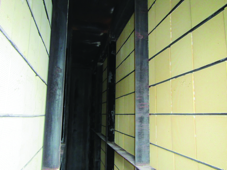
Structural Damage Caused by Thermal Cycling. The engines have between 1,400 and 1,600 starts since commissioning. High cycle rates combined with the high catalyst inlet temperature at low load has caused brick damage, such as crushing at the bottom brick rows, and resulted in gaps opening above the top brick rows. Engines are taken off-line periodically to clean the brick and to plug gaps identified during inspections.
High-temperature non-titania-based SCR catalyst is available. HBGS staff intends to consult with Wärtsilä and catalyst suppliers to identify high-temperature catalyst that is compatible with its operating conditions, if such catalyst is available.
NH3 Flow Control
The plant’s originally supplied NH3 flow control hardware did not allow good NH3 flow control at low engine loads in dual-fuel operation. In addition, the injectors, atomizing components, and exhaust mixing equipment supplied were sized for full-load diesel operation and were highly inefficient at low loads in dual-fuel mode. The result was high over-injection rates and NOx production in the oxidation catalyst. Facility staff has continued to fine-tune atomizing air rates and adjust injectors at low loads to find the optimum setpoint.
HBGS staff was hesitant to add a parallel NH3 injection system sized for dual-fuel mode operation. The exhaust pipe mixing equipment was sized to mix NH3 and exhaust gas in diesel mode and cannot be changed. In addition, no additional ports were available to house low-flow injectors. However, the addition of new dual-range variable-flow-coefficient valves has greatly improved NH3 flow control during low-load dual-fuel operation. The NH3 flow trends have stabilized and NH3 consumption has decreased.
Waste Gate Tuning
As mentioned previously, the waste gate bypasses exhaust gas around the turbocharger turbines to control charge air (combustion air) pressure. Operating experience indicated that a charge air pressure swing of 2 psid or greater would cause the NH3 injection control system to over-inject, resulting in higher stack NOx values.
At HBGS, all charge air pressure swings have been the consequence of a malfunctioning waste gate. Once the waste gate swing was eliminated, the result has been more stable emissions and more stable NH3 flow control.
Additionally, engine temperature control swings also cause emissions swings. In that case, CO and NOx can swing and result in loss of NH3 control. However, temperature control issues have proven to be rare at HBGS.
Catalyst Brick Availability
Catalyst brick availability is highly volatile. In HBGS’s experience, catalyst suppliers do not maintain large catalyst brick inventories. Orders placed by other facilities often deplete stocks, resulting in lead times of three months or more.
HBGS has developed relationships with three different catalyst suppliers familiar with engine-based generation. In addition, the plant has started looking into the future more than usual to maintain in-house inventory levels higher than originally recommended.
A Successful Effort
In HBGS’s case, there was almost no previous operating experience to draw upon. HBGS is one of the first facilities utilizing the Wärtsilä W18V50DF A engine technology in a heavily cycling mode with such a low permit level condition. The expected catalyst life was based on the only available information, which came from the shipping industry. The shipping industry, however, typically is operated under different conditions, including less-stringent permit conditions, and the engines operate near full load while steaming (>75%).
The HBGS team has been fully engaged in the effort of identifying corrective actions to help operate the plant within its permit parameters by fully understanding the limitations of its catalyst system. The staff’s philosophy is one of continual improvement, and it has found studying the issue and identifying further improvement to be an exciting endeavor. ■
—Silas Biggin is power generation plant engineer; Chris Brittain is operations and maintenance supervisor; Chuck Holm is plant manager; Jill Lorenc is power plant assistant; and Scott Washington is environmental field specialist for PG&E Humboldt Bay Generating Station.