Electric power production from coal is on a steep rise in major developing countries, including China, India, Indonesia, South Africa, and Vietnam, albeit declining in developed countries such as the United States. Shortfalls in coal production have been reported in some of these countries, but these issues are being addressed by increasing coal production, as well as by use of imported coal from other countries. The major concerns of Pulverized Coal (PC) or Circulating Fluidized Bed (CFB) combustion type coal-fired power plants are fires and explosions in hazardous areas and global warming and other environmental issues. Fires and explosions have caused a significant number of deaths and injuries to power plant staff. Besides other ignitable materials used in coal-fired power plants, coal dust has been identified as the major source of these fires. For coal to remain as a viable fuel in power production in the power generation industry, protective measures are required during engineering, design, construction and operation of the coal-fired power plants, particularly in electrical areas that are often a source of ignition.
The Fire Triangle
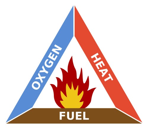
The “fire triangle” (Figure 1) is a well-known tool that illustrates the three conditions that must be present for a fire or explosion to occur at a particular location: Flammable or combustible material must be present; the material must be mixed with air in the proportions and concentration to form a combustible mixture; and the ignition source must supply enough energy to initiate combustion. A spark or flame is not necessary, as temperature alone can supply the energy to cause ignition of the mixture.
The energies required to ignite various groups of combustible substances have been proven by experimentation. The concepts included in the fire triangle have been specified in codes and standards issued by various world organizations providing guidance in the design of electrical systems, selection of equipment, and construction and operation of power plant facilities.
Hazardous Classified Locations
The National Electrical Code (NEC) in United States and International Electrotechnical Commission (IEC) in other countries define hazardous area locations as those areas, where fire or explosion hazards may exist due to presence of combustible dust or ignitable fibers, flammable gases or vapors, and flammable liquids. Electrical equipment can become a source of ignition in these volatile areas.
Hazardous areas are classified by types, division or zone, and nature/group. There are three types of hazardous conditions, Class I—Gas and Vapor, Class II—Dust, and Class III—Fibers and Flyings. Hazardous area locations are categorized by two methods per NEC:
- Class I, II, and III, and Division 1 and 2 Method: Article 500
- Class 1, Zone 0, 1 and 2 Method: Article 505 and IEC/EN60079-10.
The “class and division” method has traditionally been used in the United States. The “class and zone” method has been used in other countries in accordance with IEC standards.
There are two types of divisions under Class I conditions:
- Where ignitable concentrations of flammable gases, vapors or liquids can exist all or for some time under normal operating conditions
- Where ignitable concentrations of flammable gases, vapors or liquids are not likely to exist under normal operating conditions
Similarly, there are two types of divisions under Class II conditions:
- Where ignitable concentrations of combustible dust can exist all or for some time under normal operating conditions
- Where ignitable concentrations of combustible dust are not likely to exist under normal operating conditions
Zones defined per IEC standards are as follows:
- Zone 0. Where ignitable concentrations of flammable gases, vapors or liquids can exist all of the time or for long periods at a time under normal operating conditions.
- Zone 1. Where ignitable concentrations of flammable gases, vapors or liquids can exist some of the time under normal operating conditions.
- Zone 2. Where ignitable concentrations of flammable gases, vapors or liquids are not likely to exist under normal operating conditions.
Nature/Groups of Hazardous Substances are:
- Group A, B, C and D in Class I locations
- Group E, F and G in Class II locations
Combustible and Flammable Materials in a Coal-Fired Power Plant
Many types of combustible and flammable materials can be present in coal-fired plant:
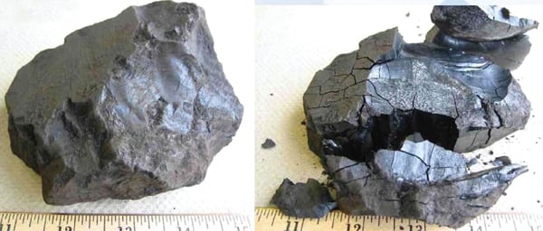
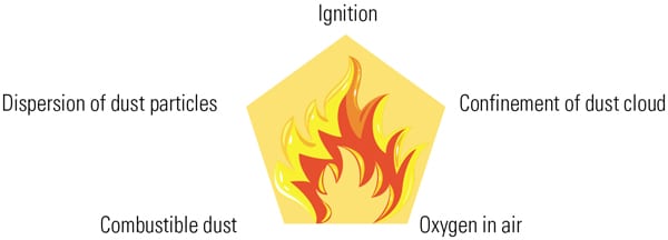
Coal. The main combustible fuel. In addition, coal dust is a major source of dust explosions in a coal-fired power plant. It can cause primary explosion when the right concentration of finely divided dust, suspended in air, is exposed to a sufficient source of ignition causing combustion. If this primary explosion occurs, additional available dust can disperse and secondary explosions can spread throughout the facility.
Propane. Used as start-up fuel. It can be present in gas cylinders, piping to ignition burner and to combustor, gas shut-off valve, gas control valve block, gas-relief valve.
Natural gas. As start-up or alternate fuel. Gas can be present in gas compressor station, filter and scrubber station, gas pre-heater areas, gas shut-off valve and filter, gas control valve block, gas relief valve, and gas piping.
Fuel oil. As start-up or alternate fuel. Can be present in oil tanks, fuel unloading and forwarding pump station, fuel oil booster pump and leakage tank, fuel oil control valve block and fuel oil piping to burners. The fuel oil becomes flammable when heated above its flash point.
Hydrogen. As cooling medium for generator cooling and release from DC system batteries. Also present in hydrogen gas unit, seal oil unit, control cubicle and piping.
Ammonia. Aqueous ammonia is used for nitrogen oxide emission reduction by selective catalytic reduction (SCR) or selective non-catalytic reduction (SNCR) method. Includes ammonia storage and piping.
Sources of Ignition: Electrical Equipment
There are 3 ways in which electrical equipment can become a source of ignition:
Arcs and sparks. Produced by the normal operation of equipment, e.g., motor starters, contactors, and switches can ignite a combustible or a flammable material.
High temperature. Some heat producing equipment, such as light lamps and lighting fixtures, electric motors and heaters can ignite flammable atmospheres if they exceed the ignition temperature of the hazardous material.
Electrical equipment failure. Shorting of a terminal could spark ignition.
Electrical equipment can cause explosions in coal dust atmospheres when located in coal conveyor galleries, transfer towers, head chute, flop gate bunkers, coal preparation system/crusher house, coal silos, and feed system, totally enclosed portions of coal handling conveyors, coal handling below grade conveyor systems, coal chutes, dust collectors, and other locations where dust can settle, hidden concealed areas, and where other combustible and flammable materials exist.
Similarly, electrical equipment can cause explosions in propane gas, natural gas, fuel oil, hydrogen gas and ammonia gas areas, where flammable conditions exist.
Selection and Installation of Electrical Equipment for Hazardous Locations
Ignitions, combustion and explosion within electric equipment and circuit wiring enclosures in hazardous areas are due to hot surfaces and arcs/sparks, or combustible material entering the enclosures. The ideal electrical enclosure should be installed and removed easily, protect the equipment, allow the components housed inside it to be accessed easily, and resist and prevent fire and explosion hazards. NFPA 70, NFPA 79, NEMA 250, UL 50, UL 508A; Canadian Standard Association CSA 22.2, and IEC 60529 provides guidance in the selection of specific type of enclosure to match the environmental protection.
Equipment protection methods include flameproof, encapsulation, oil emersion, dust ignition proof, dust tight, powder filled, non-sparking, non-incendiary and hermetically sealed construction. Many of these methods apply to AC-powered circuits, but few are used for instrument wiring circuit wiring.
When installations are not explosion proof or intrinsically safe, pressurization is often used to maintain the classified area safety. Wiring and enclosures are protected using a positive pressure maintained within the enclosure, junction boxes and conduit as per ANSI/NFPA 496.
Intrinsically safe circuits in which any spark or thermal effect is incapable of causing ignition of a mixture of flammable or combustible material in air, may be used in hazardous classified locations. NEC Article 504 requires that conductors and cables of intrinsically safe circuits shall be physically separated from non-intrinsically safe circuits. Nonincendive circuits, in which any spark or thermal effect produced under intended operating conditions is not capable of igniting the gas-air, vapor-air, or dust-air mixture, may be used for equipment in Class 1, Division 2 and Class II, Division 2 hazardous classified locations.
Electrical Equipment for Class I Applications (gas/vapor)
Class I, Division 1 equipment is used with the assumption that hazardous gases or vapors will be present and eventually seep into the enclosure. Therefore, construction of such equipment must be strong enough to contain an explosion within, and be explosion proof. It must function at a temperature below the ignition temperature of the surrounding atmosphere providing a way for the burning gases to escape from the device as the gases expand during an internal explosion, only after they have been cooled off and their flames quenched. The escape paths could be ground surface or threaded flame path. Further, it is imperative to ensure that all flame paths are protected during handling, shipping, storage, installation and maintenance of explosion proof material and equipment.
Electrical Equipment for Class II Applications
Class II, Division 1 equipment is designed and constructed such that it must seal out the combustible dust, operate below the ignition temperature of hazardous substances, and allow for a dust blanket. Therefore, there is no need for heavy explosion-proof construction, or flame paths required for equipment in Class I, Division 1 locations. Class II equipment is called dust-ignition proof.
Electrical Equipment for Class III Applications
There is very little difference in the design between Class II and Class III equipment. Class III equipment must minimize entrance of fibers and flyings, prevent escape of sparks, burning material or hot metal particles resulting from failure of equipment, and operate at a temperature that will prevent the ignition of fibers accumulated on the equipment. Class III equipment is generally not used in coal-fired power plants.
There are many devices, fixtures and enclosures that are suitable for Class I, II and III locations. Additionally, a Class I device would have to prevent dust entering the enclosure to be suitable for Class III application.
Low Ambient Conditions Considerations
Explosion proof– or dust ignition proof–equipment is generally suitable for use in an ambient temperature range of -25°C (-13°F) to +40°C (+104°F). Such equipment may not be suitable for use at temperatures lower than -25°C (-13°F), unless they are identified for lower temperature service.
Equipment that is approved for Class I and Class II or Zone 0 and Zone 1 should be marked with the maximum safe operating temperature. Equipment must be selected so that its maximum surface temperature will be less than the ignition temperature of the coal dust.
Installation Considerations
Proper installation of electrical equipment in a hazardous location requires use of seals. Special fittings are required to keep hot gases from travelling through the conduit system igniting other areas if an internal explosion occurs in a Class I device.
Coal handling buildings that have dust explosion hazards, structural members should be carefully reviewed for explosion pressures. Also, proper pressure relieving vents and wall panels should be selected, located and provided.
Qualification of Electrical Equipment in Hazardous (Classified) Locations
There are a number of ways of protecting electrical equipment so that it does not cause an explosion when used in a surrounding flammable atmosphere, or ignite a layer of dust on the equipment. The two most common ways are explosion-proof equipment and dust-ignition proof equipment
Electric motors should be totally enclosed fan-cooled, Class II, Division 2/Zone 1 type or totally enclosed pipe-ventilated type, meeting temperature rise limitations.
In Coal handling areas, where accumulation of coal dust and its suspension in air are sources of potential hazards, medium voltage switchgear and low voltage switchgear enclosures should be fully gasketed and be provided with filtered and screened air.
Dust ignition–proof equipment should be enclosed in a manner that will exclude dust and constructed so that arcs, sparks, or heat generated inside of the enclosure will not ignite exterior accumulation or atmospheric suspension of a specified dust on or in the vicinity of the enclosure.
Electrical devices including switches, solenoids, panels, should be used with NEMA 9 (dust ignition–proof) enclosures with watertight seals (O-rings), which together with the enclosed equipment in each case, shall be as complete assembly for Class II, Division 1, Group F locations.
NEC Article 500.8 (A) states that the suitability of identified equipment shall be determined by the equipment listing or labeling (for example, UL), evidence of equipment evaluation from a qualified testing laboratory or inspection agency, or evidence acceptable to the authority having jurisdiction.
Applicable Industry Codes and Standards
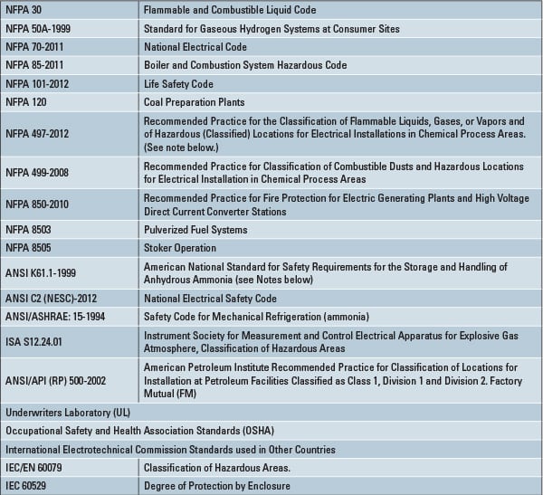
In the United States, codes and standards have been developed that are applicable to hazardous classified areas as shown in Table 1.
Table 1. Codes and standard applicable to hazardous classified areas. Source: Burns and Roe Enterprises.
Design Basis Document (DBD) and Drawings
A design basis document is an engineering document that defines the basis of engineering and design, and the selection of electrical equipment that must meet requirements for each classified area. The design basis document also provides the necessary guidance to inter-discipline team of engineers in the design of their systems and design drawings for classified areas.
The design basis document and design drawings should include:
- A listing of all combustible and flammable materials used in the facility, along with their pertinent properties, such as ignition temperature, flash point, density and how and where handled.
- Brief description of the process, operation, maintenance and cleaning procedures, and assumptions.
- A list, including dates and/or editions of all the codes, standards, references, practices, and other data used to prepare area classification.
- A listing of each room or area and its determined area classification, along with the rationale for making such determination.
- A complete set of electrical area classification drawings, indicating process flow, process equipment, the normal leakage sources, and the boundaries of area classifications.
Practical Guidelines
Table 2 provides general practical guidelines for classification of electrical areas where combustible and/or flammable materials are located and processes are performed in a coal-fired power plant. The following is a list of NEC rules that are intended to convey an awareness of the complexity of electrical design in hazardous areas:
- Explosion proof and dust-ignition proof equipment is required in Division 1 (Zone 0) areas and for certain types of equipment in Division 2 (Zone 1) areas.
- Approved equipment by UL or other appropriate agency should be preferred.
- Electrical equipment should preferably be located outside hazardous area.
- General-purpose equipment is permitted for certain applications in Division 2 (Zone 2) areas.
- Purging and pressurization of enclosures are permitted to prevent entrance of flammable and combustible materials, provided the specific rules of NFPA 469 are followed.
- Instrument enclosures may be general-purpose type if they are part of intrinsically safe systems, and if they are installed per NEC article 504.
- Rigid metal conduit is the allowable wiring method in Division 1 areas.
- Cable tray and cable, under certain conditions, are permitted in Division 2 areas.
- Electrical equipment must have temperature ratings or operating surface temperatures below the AIT of the hazardous substance present.
Table 2. Guidelines for classification of electrical areas. Source: Burns and Roe Enterprises.
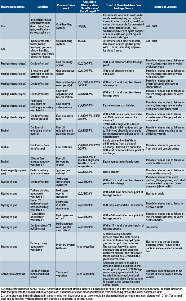
Sound engineering judgment should be applied and additional areas, not mentioned in Table 2, should be identified. Equipment manufacturer’s recommendations for area classification of specific equipment should be followed, if they are more stringent than the guidelines provided in Table 2.
When there is more than one leakage source in an area, such as in a manifold having several instruments, valves and flanges, or if there are several pieces of equipment with potential leak sources, the area should be boxed out as an overall 3 dimensional shape covering limits of extreme leakage points.
In addition to the recommended distances from sources, considerations should be given to use easily recognizable boundary limits when defining the horizontal and vertical extent of classified locations. Examples of recognizable boundaries are column lines, walls, ceilings, coordinates, equipment outlines, roads, dikes, etc. Areas identified by recognizable boundaries are helpful for plant installation, operation and maintenance personnel.
To avoid undue expense, precaution should be taken to verify that boxing an overall area or extending a classified area to recognizable boundaries does not include electrical equipment that would otherwise not be included in the hazardous area.
Project Documents
Project documents prepared and used in establishing hazardous areas include process flow diagrams of the systems containing the hazardous materials, piping layouts, equipment general arrangements, and vendor supplied equipment drawings
Two examples may be illustrative. The first shows a typical example of a pulverized coal-fired power plant coal handling system process flow diagram, and the second shows boiler general arrangement with classified hazardous locations.
The design basis document and the associated design drawings that show the extent of horizontal and vertical boundaries of each classified area should be discussed with the owner, the construction contractor and the plant operators for their understanding of the affected areas. It also helps the plant operation personnel to take protective measures that ensure safety of operation and maintenance of plant and better understanding to inspectors and insurance personnel.
—Ram K. Saini, P.E. is assistant chief electrical engineer with Burns and Roe Enterprises.