The requirements placed on belt conveyors have become increasingly complicated with respect to predictable and reliable operation and the reduction of fugitive, especially dust, emissions. The proven techniques of using engineered-flow chutes and air-supported belt conveyors can be found at many coal-fired power plants and this equipment can be retrofitted to any station.
No longer is it sufficient for the conveyors merely to move material from point A to point B. Now these systems must be able to produce a specified continuous flow, enabling a plant to operate without peaks and valleys in the amount of delivered fuel. In addition, the conveying system must provide effective material control to minimize the problems and costs associated with the escape of fugitive material. These problems include unscheduled shutdowns, premature equipment failures, regulatory concerns, poor relations with neighbors, and health and safety issues.
However, new technologies are available that can improve the performance of conveyors handling coal and other bulk materials. Two of these technologies are air-supported belt conveyors and engineered-flow transfer chutes. Used separately or in combination, they offer a plant the opportunity to dramatically improve material-handling operations and overall plant efficiency. Conveyor designers are also making an effort to accommodate needs for future upgrades and special components that improve performance before the equipment is actually built.
Engineered-Flow Transfer Chutes
The loading and discharge of conveyor belts is the area where many, if not most, of the problems in solids conveying occur. Fortunately, a new technology provides chutes to accomplish conveyor loading and discharge without blockages while minimizing the dust generated: engineered-flow transfer chutes.
Traditionally, chutes have been an afterthought in material-handling design. They are installed to connect two structures—one conveyor to another, a conveyor to a vessel, or a vessel to a conveyor. Little consideration has been given to the flow of material through the chute beyond making sure the chute was big enough to be (mostly) out of the way of the material stream. Chutes were kept small to avoid running up expenses for steel. Because these enclosures were designed with the minimum cross-section, they were prone to buildups and blockages.
Conventionally designed chutes also generate dust. When a granular material moves through an enclosure like a chute, the material imparts momentum to the air surrounding the body of material and filling the chute. The effect is the induction or “carrying along” of quantities of air with the stream of material. If, in its passage through the chute, the body of material is allowed to disperse or open up, even more air is carried along, both on the inside and on the outside of the moving stream. Then, when the stream of material “crash lands” on a receiving conveyor, the profile of the material is compressed and the induced air is driven off. This air takes with it the smaller particles of material as airborne dust. If the stream carries large amounts of induced air, then more dust is released into the air. If the cargo lands in the loading zone with higher impact energy—if it has fallen farther or was moving faster when it hits—it releases this air with a higher velocity, again creating larger amounts of dust. If the material has been allowed to move in a disorderly, turbulent stream—which could be called “billiard flow,” where the lumps bounce off each other and the walls—the material lumps will degrade, creating more dust that can be carried out.
However, if the material is kept as a tight, coherent stream, the amount of induced air is minimized. Less air is released and less airborne dust created. The material moves smoothly—like water through a faucet—rather than with the starts and stops, the acceleration and deceleration that cause problems. The material slides on itself in a “fluid flow” rather than bouncing in the typical billiard-flow fashion.
Chutes with “engineered flow” represent the application of the principles of fluid mechanics and the understanding of particulate movement to provide the basis for the design of a transfer chute. These chutes are designed so that the material stays in continuous motion though the transfer chute.
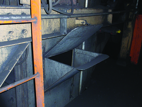
The Hood and Spoon
Engineered-flow chutes are designed to provide a continuous stream of material in conveyor loading and discharge applications. These chutes include a “hood” discharge chute and a “spoon” receiving chute (Figure 1). In addition, they feature a flow-engineered enclosure that contains the stream of material as it leaves the head pulley until it is deposited onto the receiving belt at as close to belt speed as practicable without increasing the risk of plugging. This reduces impact that degrades the material and wears the belt, and it minimizes air expulsion that drives dust into the air.

1. An engineered-flow chute incorporates a “hood” that directs the material flow down in a cohesive stream and a “spoon” to place the cargo on the receiving belt. Source: Martin Engineering
Even if the two conveyors run at the same speed, the downward component of the material flow will cause the velocity of the material to increase if the flow is left unrestrained. Both the hood and the spoon are designed to intercept the material trajectory at a low angle of incidence. This uses the natural forces of the flow to steer the material into proper position on the receiving belt with reduced impact. Because the hood and spoon are designed with both the material specifications and the flow requirements as criteria, the chute can operate at the required flow without risk of plugs or chute blockages that will choke operations. The key to success is the proper design of the hood and spoon.
Parametric Design Procedure
Engineered-flow transfer chutes are developed using a parametric design procedure; that is, they rely on the information provided in a set of specifications to develop the chute for a given transfer point. The process uses material testing and the conveyor system specifications to develop the chutes using design software.
Any 3-D design using a parametric model must be based on rigorous processes and procedures to provide a precise, accurate, and complete design. Some of this data can be determined from a site survey or (particularly for new facilities) from a review of the site plans and conveyor specifications. These data include belt speed, belt width, trough angle, angle of incline/decline, actual and maximum flow rate, the material cross-sectional area at the conveyor discharge, and the length of conveyor transitions for both discharging and receiving conveyors.
For retrofit projects, a “point cloud” survey may be conducted to confirm locations, clearances and obstructions, which must be taken into consideration when developing the fabrication drawings. This information will also help to ensure accurate fit-up of the individual components (Figure 2).

2. A “point cloud” survey may be conducted to confirm locations, clearances, and obstructions when designing a material-handling system. Source: Martin Engineering
Testing samples of the conveyed material provides other important data. Information analyzed includes material composition and physical properties, moisture content, lump size range, and fines size. Testing will determine the range of material characteristics—the levels of cohesion and adhesion, the extremes of particle size, and the material’s angle of repose. After the various conveyor and material parameters are determined, the material discharge trajectory can be determined. In combination with the established parameters, this trajectory is the basis for development of the chutes.
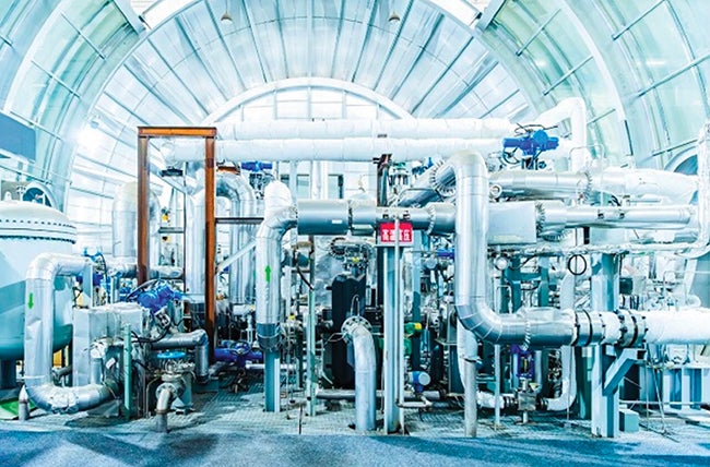
These accurate and detailed parameters are used in developing a computer-generated 3-D model of the chute system. One advantage of the computer-based system is that changes can be quickly developed to compensate for changes in the system characteristics. This allows the engineer to easily see the effect of any proposed changes—how a modification in belt speed, pulley diameter, or lump size will alter the material’s trajectory and fall (Figure 3). The model can be used to check for conflict between the proposed design and existing equipment. Following customer approval, the 3-D model can be used to produce the fabrication and installation drawings.
3. This image is a computer animation of a single frame of material flow used in developing the design for engineered-flow chutes. Source: Martin Engineering
Case Study of a Chute Retrofit
One example of the improvements offered through the use of engineered-flow chutes is at a coal-fired power plant in the Midwestern U.S. The AmerenUE Meramec Power Station is a four-unit plant that burns approximately four million tons of Powder River Basin (PRB) coal a year. However, chute problems kept the plant from achieving the designed 1,000-tons-per-hour flow rate. Discharge chutes taking the coal from the conveyors into the bunkers above the boiler feed mills would plug when tonnages climbed above 550 tons per hour. Although the conveyor chutes had been recently renovated, this choking problem was not resolved and the system never operated at design capacities.
To maintain full-load operation of all four units, Meramec was forced to operate both sides of its redundant coal-handling conveyor system and run coal nearly around the clock. Consequently, it was difficult to provide necessary conveyor maintenance, and manpower expenses for overtime increased. In addition, this posed the risk that equipment failure or an emergency outage of one of the conveyors would require the plant to reduce output.
The most troublesome bottleneck in the plant was located in the bunker room, where two identical 90-degree transfer points dropped the coal approximately 12 feet onto the tripper belts to the storage bunkers. These bunkers supply the pulverizing mills that feed the boilers.
Plant officials felt a need to increase the material flow rate so the plant could put more material through one conveyor system without increasing chute plugging and without increasing the problems with dust from the PRB coal. While the plant was interested in improving chute performance, it was the prospect of reduced dust that convinced the corporate engineering staff to try the flow-engineered chutes. To evaluate the success of the engineered chute’s dust control abilities, a comparison-testing program was established.
The Dust-Testing Program
By carefully collecting and weighing the material, plant officials could assess the amount of material lost from the coal-handling system before and after the flow-engineered chutes were installed. To establish dust levels before installation of the new chute, dust was collected over a three-day, 24-hour-per-day period. A pan-and-bucket system was used to collect spillage and heavy dust; this method is approved for Best Available Control Technology (BACT) testing (Figure 4). Results showed that during an average daily run of 4,297 tons of coal, the conveyors would lose over 7,614.637 grams (16.75 pounds) of dust. This represents a loss of 1.810 grams per ton (Table 1).
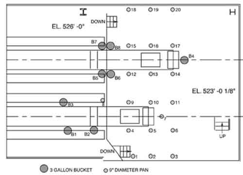
4. Dust-testing container placement plan. Source: Martin Engineering
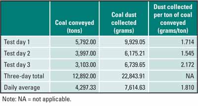
Table 1. Dust collected before installation of an engineered-flow chute. Source: Martin Engineering
Installation and Testing Results
New chutes utilizing the engineered-flow concept were designed and installed. After the new chutes were installed, a similar three-day test was conducted. The collecting pans were placed in the same locations, and the samples were gathered and weighed daily.
Following installation of the engineered chutes, testing showed that the loss of material was reduced to 0.022 grams per ton—a reduction of 98.77% in the amount of material lost per ton (Table 2). This reduction was accomplished despite increasing the overall volume of coal handled by more than 70%. These results indicate that the project was successful in achieving improved dust control while allowing an increase in tonnage.

Table 2. Dust collected after installation of an engineered-flow chute. Source: Martin Engineering
In addition, the new chute design has allowed the plant to increase the volume of coal handled by more than 70%, from 550 to 950 tons per hour, without requiring the installation of dust collection systems. At present, the plant operates without any “baghouse” dust collection system, and plant officials hope to keep it that way.
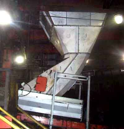
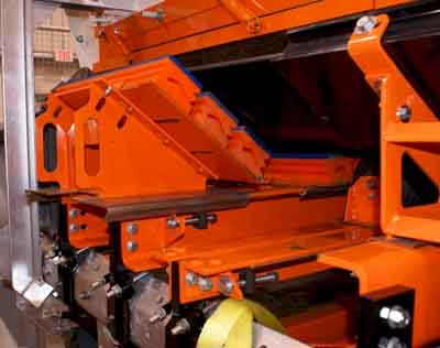
Installation of the chutes has allowed the plant to achieve its goals for both higher flow rates without blockages and for decreased levels of coal dust (Figure 5).

5. Engineered flow chute installed at the AmerenUE Meramec Plant. Courtesy: Martin Engineering
Air-Supported Conveyors
Air-supported belt conveyors are conveyors that have replaced the carrying idlers common to conventional belt conveyors with a film of air rising from a troughed pan. Air-supported conveyors can be used for the transportation of most bulk materials, and they offer significant energy, environmental, and safety advantages over roller conveyors.
Air-supported conveyors are also becoming more popular because new designs make the technology cost-competitive with roller conveyors. Solids-handling facilities are seeing that air-supported belt conveyors are an ideal solution for applications where a high level of control over dust and spillage is required.
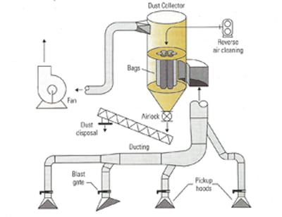
The principals of operation are simple. A film of low-pressure air supports a conventional troughed conveyor belt. Standard head pulleys, drives, and tail pulley constructions are used. The load zone and carrying sections of the conveyor can all be contained in plenums that are pressurized with a low-pressure centrifugal fan (Figure 6).
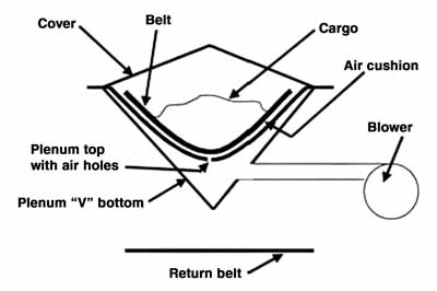
6. V-Plenum air-supported belt conveyor. Source: Martin Engineering
The upper (carrying) surface of the pan and plenum is typically shaped to the same profile as a belt conveyor with a 35-degree trough. When the conveyor belt lies in the trough, it assumes the shape of the trough. Holes in the top of the plenum allow a film of air to form between the belt and the plenum. The return run does not have to be air supported and, in fact, many applications incorporate conventional (flat) return idlers on the conveyor.
In most cases, uneven and intermittent loading of material has no effect on the operation of the air-supported conveyor. However, conveyors with high-impact loading or heavy-duty applications may not be suitable for an air-supported application.
Advantages of Air Support
Air-supported conveyor systems offer a number of advantages over conventional troughed idler conveyors, including those that follow:
- Effective dust control. When the air-supported system is utilized from the loading area to the head chute, total dust control can be achieved (Figure 7).
- Stable belt path. Troughing idlers spaced along the conveyor create hills and valleys in the belt line where the cargo is agitated and begins to segregate; the fines end up on the bottom and larger pieces on top. The air-supported conveyor offers a smooth ride for the cargo, with less spillage, segregation, and degradation of material.
- Lower operating cost. On horizontal conveyors, the air-supported conveyors can use up to 30% less energy; on inclined conveyors, the energy saving is up to 5%.
- Reduced maintenance expense. There are no carrying-side idlers, so there are no rollers to replace and no idler lubrication is required.
- No skirtboard seal. No skirting is required in the loading area, because the chutewall/wear liner forms a barrier to contain the material being loaded.
- Retrofit availability. New designs allow air-supported conveyors to be installed on existing (conventional conveyor) stringer and support systems. Air-supported and conventional roller sections can be mixed in a single conveyor to allow for loading zones, tracking idlers, belt scales, or other requirements.
- Improved product condition. An air-supported belt is gentle on the cargo. There is no bumpy “roller coaster” ride over the idlers, so there is no material segregation, no product degradation, and no breakage. Because the conveyor is fully enclosed, there is no contamination of conveyed material.
- Greater inclines allowed. By eliminating load agitation, air-supported conveyors can allow for steeper inclinations, depending on the bulk-material properties.
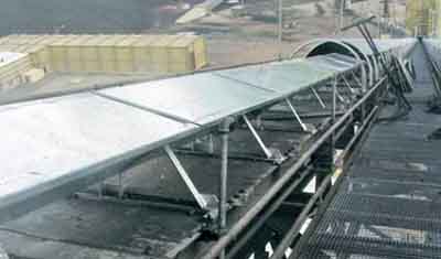
7. A fully enclosed, weather-resistant, air-supported conveyor will minimize material segregation, spillage, and dust. Courtesy: Martin Engineering
Considerations for Air-Supported Belt Conveyors
Certain air-supported belt conveyor requirements must be included in the system design that differ from those for the conventional roller conveyor. These requirements include:
- Center loading. Central loading of the cargo is critical to proper belt tracking and the prevention of material spillage inside the plenum. Light-duty to moderate-duty applications (with minimal loading impact) are the best fit for this technology. This system is well suited for use with the flow-engineered loading chutes discussed earlier.
- Vulcanized splices. Belts with vulcanized splices are usually required to avoid damage to the plenums. The use of mechanical splices may void warranties.
- Design detail and workmanship. Design detail is more critical, and design mistakes can be more costly to rectify than with conventional conveyors. Workmanship during manufacturing and installation is more critical than on conventional conveyors, as the plenum sections must be identical and air leaks are not permitted.
- Belt-cleaning systems. Air-supported conveyors require aggressive belt-cleaning systems to ensure that carryback is controlled. Carryback may also blind the air supply holes when allowed into the plenum area.
- Material surges. Surges of material must be avoided because the system is totally enclosed, and blockage and system shutdown could occur.
Case Study of an Air-Supported Conveyor Retrofit
In coal-fired power generation, air-supported conveyors are a particularly attractive solution as an improved method of controlling dust. The totally enclosed plenum improves dust control over the current state-of-the-art methods of sealing conventional (idler-supported) conveyors.
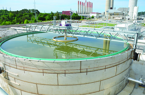
A recent application was the use of an air-supported belt conveyor to convey coal from a new stockpile/reclaim area to an existing conveyor at Colorado Springs Utilities Martin Drake Power Plant (Figure 8). Because the plant is located in a downtown area, the utility was particularly sensitive to the need to prevent dust from the very friable PRB coal from creating environmental problems. The utility installed an air-supported conveyor and has been very satisfied with both its dust control and its operating performance, even in Colorado’s cold-weather conditions.
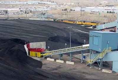
8. Colorado Springs Utilities installed an air-supported belt conveyor to carry coal from a new stockpile to an existing conveyor. Courtesy: Martin Engineering
Combination Systems: Chutes and Conveyors
Properly applied, these “leading edge” conveyor systems provide substantial benefits when used individually. Used in combination, their advantages multiply. One example was the installation at the Xcel Energy Pawnee Station in Brush, Colorado (Figure 9). Here the plant needed to upgrade its entire 30-year-old conveyor system, successfully accomplishing the project goals of:
• Restoring system capacity to 3,300 tph.
• Containing the coal to reduce spillage.
• Minimize airborne dust.
• Improve plant working conditions.
Another example is the recently completed project at the Jim Bridger Plant—now part of MidAmerican Energy Holdings—in Wyoming (Figure 10). Here, to replace systems that were not working as specified, the plant upgraded its conveyors with systems combining engineered chutes and air-supported conveyors. The project achieved its goals of increasing the economic benefit of the plant (reduced dust and spillage, cost of dust suppression, and labor), decreasing maintenance costs (belt cover wear and improved belt loading pattern), and increasing the safety of plant operators (reduced chute fires and risk of dust explosions).
9. Engineered flow chute and air-supported belt conveyor system installed in combination at Xcel Energy’s Pawnee Station. Courtesy: Martin Engineering
10. Engineered flow chute loading an air-supported conveyor at the Jim Bridger Plant. Courtesy: Martin Engineering
Modern Conveyor Architecture
Modern design techniques—such as 3-D modeling for fabrication and discrete element modeling for chute design—can be used to improve conveyor reliability, productivity, and safety while reducing the total cost of ownership. To achieve clean, safe, and productive designs, designers should also consider a new hierarchy for design decisions, detailed below.
Capacity. Following design principles that establish safe, service-friendly, and easy-to-clean belt conveyor systems leads to better and more productive operating systems. A cleaner, safer operation is normally a more productive operation in the long run. Safety issues normally correspond to unsafe operating conditions, which are also detrimental to the equipment. Airborne dust can find its way into lungs and bearings; material can accumulate under and on walkways and conveyors, leading to trip, slip, and fall hazards. These unsafe operating conditions are hazards not only to health but also to the condition of the conveyor equipment. When equipment is shut down for unscheduled repairs, it cannot be productive.
Safety and Code Compliance. Applying design principles to help ensure worker safety should include the use of barrier guards and the implementation of new designs that will improve the ease of cleaning around and changing out equipment.
Control of Fugitive Materials. Cleaning around conveyors is a necessity. By eliminating places where fugitive materials accumulate, cleaning requirements are reduced and simplified. Horizontal structural members should be angled at 45 degrees whenever possible in order to shed material, thus making it unlikely that cleanup crew members will have to reach under the belt with tools to remove buildup. Structural members that cannot be oriented to reduce dust buildup should be fitted with dust plates or caps to reduce material buildup in hard-to-clean areas.
Service Friendliness. Belt cleaners and other conveyor components can be designed to be safely serviced while the belt is running. Specialized tools can be designed and service techniques can be taught to develop authorized maintenance employees or service contractors who can safely service certain components while the belt is running (Figure 11).
11. Specialized tools and safe designs make belt-cleaner service easier. Courtesy: Martin Engineering
Repositioning wear liner so that it is placed on the outside of the skirtboard—where it can be easily inspected, accurately installed, and easily replaced—is a simple modification potentially saving thousands of maintenance hours (Figure 12). Skirtboard provides structural support; raising it above the normal flow pattern of the bulk material and implementing a small design change to the skirt-seal clamps enables the wear liner to be installed on the outside of the skirtboards. The wear liner can also be made adjustable for accurate installation.

12. Installing wear liner on the outside of the skirtboards is a simple modification potentially saving thousands of maintenance hours. Courtesy: Martin Engineering
Cost Effectiveness. The total cost of ownership, including the cost per pound of dealing with fugitive material releases, should be considered in making design and purchasing decisions. While the initial purchase price may be lower for a system with no adjustment capabilities and no consideration for future wear-component replacement, the higher costs required to properly install and maintain components, clean up fugitive materials, and cover additional equipment downtime will far exceed the costs of a system that takes these factors into consideration in the initial design.
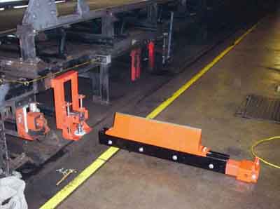
Upgradability. Designing the system for ease of future upgrades by making components track-mounted and service-friendly can reduce down time and control fugitive materials. Designers routinely consider capacity upgrades, but they rarely include provisions for component upgrades. A track-mount system provides flexibility for quickly installing different problem-solving components. The use of a preengineered mounting hole pattern in the structure around the conveyor’s transfer point allows for the installation of a new or improved system quickly and easily (Figure 13). A uniform-hole pattern for accessory mounting will encourage component suppliers to adapt modular, bolt-on, or clamp-on designs for easy retrofits.
13. This universal track allows for slide-in/slide-out maintenance. A clamp-on bracket allows for the simple installation of a track system for belt support components. Courtesy: Martin Engineering
Decisions related to the design of the conveyor system or the selection of individual components should follow a hierarchy to ensure that the best design possible is created. In the future, all bulk material–handling systems should incorporate designs to safely move the required amount of material from point A to point B in a service-friendly, cost-effective manner that controls dust and fugitive materials for now and ever more.
—Greg Bierie is global manager of project and technical sales; R. Todd Swinderman, PE is chief technology officer and board member; and Andrew D. Marti is global marketing communications administrator for Martin Engineering.