Pipes, valves, turbines, pumps, condensers, and other mechanical components in the radiologically controlled area (RCA, or hot side) of a nuclear power generation facility require routine inspection, testing, maintenance, and, eventually, replacement or repair. When technicians need to work at height, erecting a scaffold often provides the safest and most effective method of access. This article notes best practices for scaffolding, rigging, and hanging lead-filled shielding blankets in RCAs.
When scaffolding needs to be erected in an RCA, the paramount concern is minimizing exposure time. Title 10, Part 20, of the Code of Federal Regulations, “Standards for Protection Against Radiation,” establishes the dose limits for radiation workers. Although the limits vary, depending on the affected part of the body, the annual total effective dose equivalent for the whole body is 5 rem. Often, a facility’s general (or maintenance) contractor works with a scaffold supplier that can provide the necessary support services to complete work safely and efficiently, thereby minimizing dose.
Choosing a Scaffold
The two most common types of scaffold used in power plants are Systems Scaffold (which offers fast erection and the versatility of 360-degree placement on the vertical post ring sets) and tube-and-clamp scaffold (a highly adaptable system that can be erected and dismantled easily).
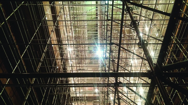
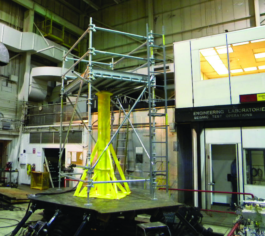
Systems Scaffold (Figure 3) has passed all seismic qualification tests of Class 1E equipment, meaning that the scaffold is in full compliance with American National Standards Institute (ANSI) requirements and the Institute of Electrical and Electronics Engineers (IEEE) Standard 344-1987. During testing performed in May 2010, equipment performed satisfactorily with no damage or dislodging of diagonals, toeboards, or planks. Tube-and-clamp and other scaffold can also pass seismic tests, but Systems Scaffold has been tested to greater extremes.
Systems Scaffold is the preferred choice for work in most areas of a power plant, because it erects and dismantles quickly. However, the geometry of post ring sets and end connectors makes decontamination more complicated. If scaffolding will be dismantled and brought back out of an RCA, tube-and-clamp is usually the preferred choice because its simplicity makes it the easiest to decontaminate—the surface areas of all components are easily accessible.
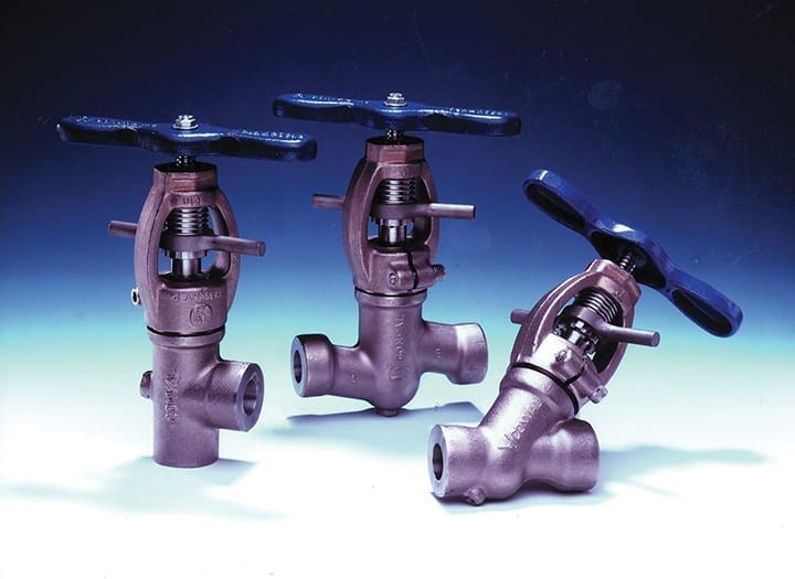
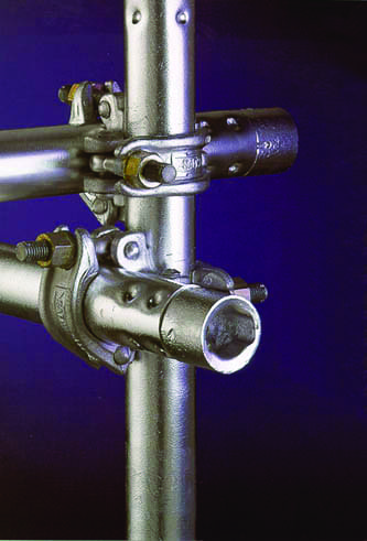
Because of tube-and-clamp’s nearly unlimited adaptability, contractors also often select it for semi-permanent residence in RCAs. Once installed, it can meet almost any access need. It is also the lowest component cost option. In addition to the standard 2-inch-wide clamp (Figure 4), 4-inch-wide military (“fat clamps”) are available, which meet or exceed U.S. Navy specification MIL-S-29180.
Engineering Support Services
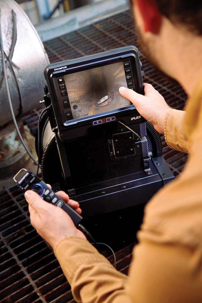
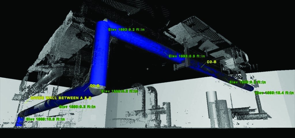
Planning often begins by managing clash and detecting clearances using software such as Navisworks or Intergraph Smart 3-D for plants. If up-to-date drawings are not available, 3-D laser surveying can produce “point-cloud” images to create 3-D drawings and models. The tool can enhance site/plant documentation and improve project planning by reducing or eliminating costly bill of material overruns and identifying clearance issues.
Although 3-D scanning has been used successfully in numerous other industries, its use in nuclear facilities has been limited. That’s because problems with decontaminating equipment could result in an expensive ($100,000) scanner being sacrificed. Nonetheless, those in the nuclear industry should be aware of this technology in case the need arises.
To help scaffold erection crews become familiar with the design of a particular scaffold, or for training purposes, the engineering team can create animations and fly-throughs that bring a 3-D model to life. When scaffold needs to support or lift heavy objects, the engineering team can use software such as STAAD.Pro and RISA to design and analyze simple to complex structures. This can be done for a wide range of load conditions such as for strain induced by gravity (dead or live loads), skip conditions, and lateral loads (including from seismic events).
Local Labor, Delivery, and Tracking
Scaffold transportation and erection within the RCA requires careful planning because of exposure limits. A scaffold that would ordinarily take four workers eight hours to build could take five times as much labor in an RCA. To properly manage exposure, scaffold builds inside the RCA literally get planned to the minute.
In one situation, for example, a single 5-ft x 5-ft x 30-ft tower scaffold took 25 workers one week to erect due to exposure limitations. A technician would hand carry in his load of parts, set them down, and walk out. Another technician would follow behind him and clamp those parts in place. Once those tasks were completed, the technicians had to spend the rest of the day in low-dose areas, because they had reached their exposure limits.
Scaffold suppliers can help contractors track every aspect of a project including build and dismantle time, part in-service time, total man-hours, cost per part, total job cost, and comparison against projections. For powerful evaluation capabilities, some scaffold suppliers also offer software tracking programs that provide costs down to the fraction of a cent. The supplier typically manages the tracking software as a value-added service.
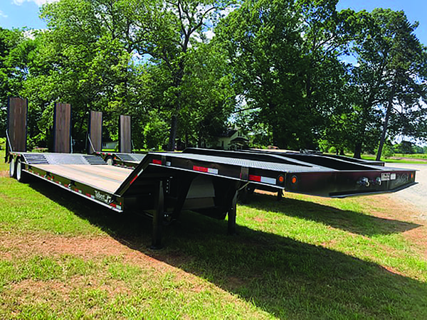
After engineering and planning, the ability to provide local labor and support is probably the factor contractors value most. A good scaffold supplier will maintain an inventory of tube-and-clamp materials and be able to deliver several thousand pieces at a moment’s notice. Delivery often takes place in wire storage racks that hold up to 700 clamps and 300 to 400 tubes. Racks aren’t just filled with parts; rather, all the components for a specific scaffold are pulled and placed in a rack. These predesigned, self-erect sets eliminate unnecessary handling. Depending on the simplicity of access and/or weight issues, the entire rack may be placed on a handcart and wheeled into the RCA.
Rigging and Shielding
While many RCAs have overhead cranes, heavy components (notably valves, flanges, and pipes) that need replacement don’t always fall within the accessibility range of installed lifting equipment. In that case, Systems Scaffold can be configured to lift a center load of up to 3,750 lb and an off-center load of up to 1,875 lb.
Configuration involves adding a bearer/runner, truss bearer, or I-beam to standard Systems Scaffold. For lifting and horizontal movement, Systems Scaffold can be configured with header beams and an underhung trolley I-beam between them (Figure 5). Depending on the length, size, and configuration of the beams, a trolley I-beam can support loads of 1,250 lb to 10,000 lb. Trolley I-beams are available in lengths from 5 ft. to 10 ft.

To shield technicians from “hot” pipes (high-dose areas) during maintenance and repair work, scaffold provides a means for hanging lead-filled blankets. If a supply of tube-and-clamp scaffold is stored in the RCA on a semi-permanent basis (and it often is), using scaffold to hang lead blankets utilizes components already on hand, a significant convenience compared to fabricating a custom rack.
While lead plate can be used, lead wool provides increased flexibility in handling. Perimeter grommets—spaced every 12 inches—enable the blankets to be easily affixed to scaffold with zip ties. The reduction in dose rate varies from 20% to 31% depending on the thickness of the lead wool blanket installed. Typically, thicknesses ranging from 3/8 inch to 3/4 inch with densities of 10 lb/ft2 to 20 lb/ft2 are used. Stacking multiple blankets can achieve a linear reduction in dose rates. While lead is heavy, the load-bearing capabilities of scaffold are well known and easily calculated.
A good access provider will help the contractor increase both safety and productivity through outstanding planning, engineering resources, on-site support, and—most importantly—good communications. ■
—Darrell Domikos is director of national equipment sales for Safway Group.