The visible consequences of sulfuric acid aerosol emissions—opaque stack emissions called "blue plumes"—are merely the tip of an iceberg. In sufficient concentration, SO3 also can increase corrosion and fouling of equipment and components downstream of the furnace while decreasing their efficiency and penalizing overall plant heat rate.
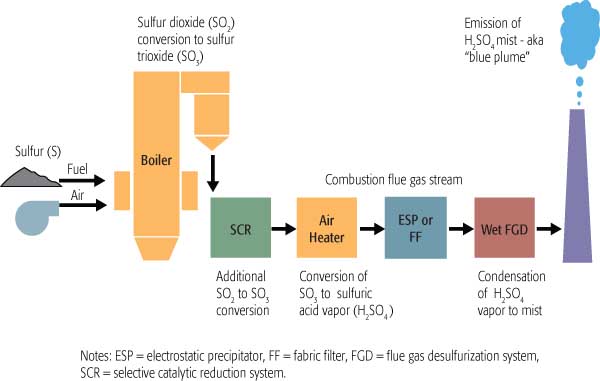
Emissions of SO3 (or its hydrated form, H2SO4) have received increasing attention due to the proliferation of selective catalytic reduction (SCR) and wet flue gas desulfurization (FGD) systems. Although much of this attention has focused on plume opacity and buoyancy, SO3 also has significant negative impacts on plant performance, operations, and maintenance. Among them are:
- Reduction of unit heat rate and increased corrosion of downstream equipment due to the raising of dew point by SO3.
- Fouling of air heaters and SCR catalysts due to the reaction of SO3 with ammonia.
- Competition of SO3 with mercury for adsorption sites on carbon particles, reducing the effectiveness of mercury emissions control.
The point at which SO3 is removed from flue gas, and to what extent, largely determine both the level of its negative impacts on plant O&M and the potential benefits achievable by its removal. Table 1 lists those benefits under four different removal scenarios. Though plume opacity and buoyancy are addressed by three of the four scenarios, the most benefits accrue to a coal-fired unit only if SO3 is reduced to a very low level (<3 ppm) upstream of the air heater (the scenario in the left column).
|
Table 1. Potential benefits of SO3 removal under four scenarios. Source: Codan Development LLC
|
If SO3 is removed downstream of the air heater but before the stack (the scenarios in the other three columns), the benefits are fewer and smaller:
- If efficient removal (to 5 ppm at the stack) is achieved between the air heater and the electrostatic precipitator (ESP), plume issues are resolved and reasonable corrosion protection is provided for equipment downstream of the injection point.
- Moderate removal of SO3 between the air heater and the ESP (to a level between 10 and 20 ppm, similar to that present during "pre-SCR" operations) reduces the risk of plume touchdown. But the plume will still be discolored, and equipment downstream of the injection point will enjoy only limited corrosion protection.
- For units configured with a wet ESP downstream of a wet FGD system, plume issues are resolved, but none of the other benefits listed will be realized.
Note that the table lists several benefits of SO3 reduction on mercury removal. SO3 and mercury compete for adsorption sites on native flyash. If SO3 is not removed prior to cooling of the gases in the air heater, the sites will be occupied by condensing SO3 (sulfuric acid), thus inhibiting the adsorption of mercury.
Part 2 of this series explained that reducing SO3 to very low levels (below 3 ppm) can enhance mercury retention by native flyash by as much as an order of magnitude. A number of researchers have reported a similar negative impact of SO3 on the ability of activated carbon to capture mercury. Accordingly, removing SO3 prior to the air heater will not only increase the capture of mercury on flyash but by injected carbon as well.
Finally, if a plant’s mercury control strategy includes the use of a high-oxidation catalyst in its SCR system for enhanced oxidation of mercury (and its subsequent removal in a wet FGD system), removal of the additional SO3 generated across the catalyst will be essential to avoid the negative operational impacts previously discussed.
The right stuff
What characteristics must an SO3 reduction technology possess? Clearly, it must be capable of very high removal efficiency during relatively short residence times. SO3 concentrations at the exit of the SCR system vary considerably from plant to plant, depending on several factors, but primarily on the sulfur content of the coal being burned and on the amount of oxidation of SO2 to SO3 by the SCR system.
Table 2 illustrates the level of SO3 reduction required to achieve a 3-ppm level at the air heater inlet under several scenarios with different combinations of fuels and SCR oxidation levels. What jumps out from the entries in the bottom row is that, in all cases, the SO3 removal technology must be extremely (90% to 97%) efficient. Also note that using a low oxidation catalyst in the SCR system decreases the required removal efficiency by only a few percentage points.
|
Table 2. SO3 reduction needed for a 3-ppm level at the air heater entrance. Note that high-sulfur coal is assumed to contain 3.5% sulfur. Source: Codan Development LLC
|
Efficacy and speed. The technology must not only remove lots of SO3 efficiently, but it also must do so very quickly. In most plants, flue gas spends only about one or two seconds (the residence time) between the SCR system and the air heater. Complicating the problem, in plants that have been retrofitted with an SCR system, the ductwork arrangement usually doesn’t provide much access for an SO3 removal technology’s reagent injection equipment. Accordingly, the requirements of an SO3 removal system should be considered early during the design of either a new plant or an SCR retrofit project.
These retrofit difficulties suggest choosing an alternative location for reagent injection, such as between the economizer and the SCR. Doing so would greatly increase the gas residence time from the injection point to the air heater inlet. This would not only make it possible to operate the SCR system at a lower temperature (benefiting both efficiency and maintenance); it also would increase SO3 removal upstream of the air heater. If chemical injection for SO3 control is done upstream of the SCR system, enough of the chemical must be added to remove the SO3 formed in the SCR.
Obviously, the SO3 removal technology and its system design also must be extremely reliable. If a plant were to commit to operation at elevated ammonia slips and lower air heater outlet temperatures, for example, SO3 reduction to very low levels would be a must.
No balance-of-plant problems. Finally, the SO3 removal system should not negatively affect any balance-of-plant equipment or systems. Technologies that inject solutions or dry solids must not cause solids to deposit in ductwork or downstream equipment. If the injection point is upstream of the SCR system, the injected chemical or the product of its reaction with SO3 cannot compromise SCR operation or catalyst life.
The same is true for injection between the SCR and the air heater. Fouling of air heaters is common, and is caused either by condensation of sulfuric acid on the unit’s heat transfer elements and its subsequent reaction with adherent ash, or by the reaction of SO3 with low levels of ammonia slip from the SCR system. In the latter case, sticky ammonium bisulfate (ABS) solids form and foul the elements. SO3 sorbents injected upstream of the air heater may also react with condensed sulfuric acid to form undesirable compounds that gradually foul the air heater.
Experience indicates that reducing the SO3 concentration in the flue gas to low levels (<10 ppm) prior to the air heater will reduce the likelihood of these secondary reactions and fouling. So another benefit of an effective SO3 removal technology is avoiding ABS fouling and secondary fouling of air heater elements. A removal technology’s balance-of-plant impacts must be addressed by its design and performance requirements.
No impact on ash. Any change in ESP performance that results from removing SO3 from the flue gas stream would represent another plant impact. Whether the impact is positive or negative remains to be seen. The presence of condensed SO3 decreases the resistivity of flyash, making it easier to collect in the ESP. Indeed, units burning low-sulfur coals frequently inject SO3 for ash conditioning, with the goal of improving the ESP’s particulate removal efficiency. If a technology removes more than 90% of SO3 upstream of the air heaters, will its absence negate the positive effect that the SO3 has on ESPs
What has been observed in early field experience with SO3 removal technologies is that this is not necessarily the case. Sodium salts also can condition flyash, so if the SO3 removal system uses a sodium-based reagent, the performance of the ESP is not likely to be reduced. A technology that uses reagents based on magnesium or calcium, however, could adversely affect ESP performance. The downsides could include increased stack opacity, degraded wet scrubber performance–and/or poorer?–quality gypsum by-product.
The removal system’s effect on the composition of particulates collected by the ESP also must be considered. If the system uses a chemical reagent, both unreacted reagent and reaction products may change the composition of solids collected in the ESP (or fabric filter). For example, the use of lime for SO3 control might put unreacted calcium hydroxide into flyash, making it harder to handle and dispose of. A more serious problem would arise if use of a reagent adds solids containing sodium or ammonia to flyash, making it unsalable on the commercial market.
Finally, there are all the cost aspects of an SO3 removal technology—the capital and O&M costs of the system itself and any additional expenses its installation may incur (for example, modifications to the air heater and/or additional ammonia consumption). However, experience suggests that these costs will pale in comparison to the considerable financial and O&M benefits that a highly effective and reliable removal system would provide.
SBS Injection technology
Codan Development LLC has been actively involved in the development of an optimal SO3 removal technology for nearly 10 years. The company’s efforts have been rewarded by the granting of two patents for what is offered commercially as "SBS Injection" technology.
The original patent, granted in October 2000, covers the injection of a finely atomized solution containing sulfite/bisulfite ions to react selectively with SO3. The second patent, dated October 2004, covers the addition of a variety of soluble compounds that react with the SO2 in the gas stream to form sulfite and bisulfite, which will then react selectively with SO3.
Since 2002, Codan has partnered with URS Corp. (www.urscorp.com) in an exclusive arrangement to commercialize the process. Both companies work together in process development and marketing activities. URS provides process design and engineering services, equipment (ranging from a minimum package of key process equipment and controls to a turnkey system), and provides process guarantees. Codan licenses the technology to users and provides intellectual property warrantees.
Figure 1 is a simplified flow diagram of the SBS Injection process. Several soluble sodium-based compounds—commercially available sodium bisulfite solution, sodium sulfite solution, sodium sulfite solids, sodium carbonate solids, and an FGD by-product solution of sodium sulfite/bisulfite—have been used as the reagent in commercial applications. The reagent is stored as a concentrated solution. If the plant receives it as a solid, the reagent is put into solution as it is unloaded. The concentrated solution then is diluted with softened water prior to injection into the flue gas. The dilution water must be low in calcium to avoid having scale form in piping and spray nozzles.
|
1. Field-tested. A simplified flow diagram of the SBS Injection process for removing SO3 from a coal plant’s flue gas stream. Source: Codan Development LLC
|
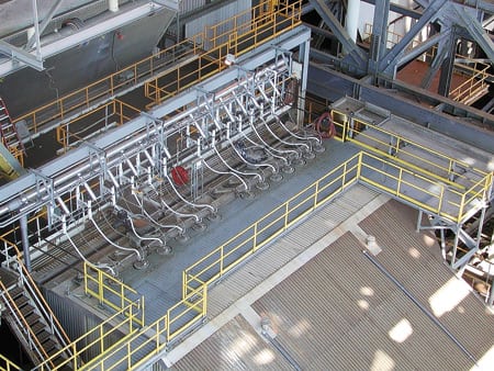
Controls maintain a constant feed rate of solution to the nozzles to achieve consistent droplet atomization. The amount of concentrated reagent in this stream also is controlled to follow flue gas SO3 concentration and unit load. The solution then is atomized by compressed air into fine droplets and injected into the flue gas stream. The droplets are converted to very small dry particles of high surface area within a few feet of the injection point. The particles then are removed with other flue gas particulates by either an ESP or a fabric filter. Figure 2 shows the injection lance arrangement at a recent installation.
|
2. Sir Lance-a-Lot. A typical arrangement of lances used to inject the soluble, sodium-based reagent. Courtesy: Codan Development LLC
|
Excellent results
To date, SBS Injection technology has been commercially installed on units totaling 8,500 MW of generating capacity, with another 700 MW under contract. As Table 3 shows, the host units range in size from 287 MW to 860 MW, while design SO3 concentrations range from 42 ppm to 110 ppm.
On existing applications, three units inject reagent upstream of the air heater and three inject it downstream. The two new installations listed in the table (as well as others in the future) will inject reagent only upstream of the air heater. As mentioned, the existing installations use a variety of sodium-based compounds. For economic and availability reasons, soda ash (sodium carbonate) will be the preferred reagent for all new applications. Currently, four of the plants listed operate the SBS Injection process only during the ozone season, when their SCR systems are in service. Two of the stations operate SBS year-round. It is assumed that when SCR systems are required to operate year-round, the SBS systems will be, too.
So far, SO3 removal efficiencies have ranged from 90% to over 98%. The systems’ effectiveness can be attributed to two mechanisms: quick liquid-phase reactions, and highly efficient dry-phase reactions from the generation of small solids with high surface areas that are very reactive with SO3.
Figure 3, representing test data from one of the existing installations, indicates that system performance using soda ash as the reagent is on a par with the performance achieved using sodium sulfite/bisulfite solution. It’s worth noting from the graph that the molar feed rate is expressed as moles of sodium injected per mole of SO3 in the flue gas. Because soda ash contains two moles of sodium per mole of soda ash, the feed ratio would be one-half that shown if expressed as moles of soda ash per mole of SO3.
|
3. Match game. This chart compares the efficacies of the SBS Injection and In-situ SBS processes. The data, from a field installation, indicate that the latter, using soda ash as the reagent, performs as well as the original, using sodium sulfite or bisulfite. Source: Codan Development LLC
|
Challenges and costs
It isn’t easy to inject a liquid into a hot, flyash-laden flue gas stream. For the process to work well and not create solids deposition issues, atomization must be reliable and consistent. Like all new technologies, the SBS Injection process has experienced growing pains as it has matured. However, improvements in process monitoring and control, better maintenance practices, and an improved injection lance design have together improved process reliability and minimized adverse balance-of-plant effects.
The systems that inject reagent upstream of the air heater (into the hotter flue gas) have generally been more reliable than those injecting downstream of the heater. For the existing installations shown in Table 3, the upstream types have been more than 98% available over a cumulative 171 months of operation. The downstream types have been greater than 96% available over a cumulative 81 months.
|
Table 3. Commercial installations of SBS Injection technology. Source: Codan Development LLC
|
The capital costs of the process depend on unit size, ease of access for locating the injection ports, and the availability of plant air for atomization. For all of the systems installed to date, as well as for the latest proposed systems, the capital costs for complete, installed systems have ranged from $5 to $10/kW. Generally, the larger the unit, the lower the cost.
Operating costs, by contrast, are highly dependent on the costs of reagent and therefore vary by reagent type and the level of SO3 reduction. Figure 4 compares the annual operating costs of SBS Injection, using sodium sulfite and soda ash as the reagents, for a typical 500-MW unit burning high-sulfur coal with an SCR system in service year-round. In both cases, the cost of reagent dominates the total, with the cost of auxiliary power (pumps and air compressor) far behind. Not shown on the bars are maintenance costs, which will be dominated by the need to regularly inspect and maintain the lances. What the bars do show, however, is that using the cheaper soda ash reduces reagent costs by over 50%.
|
4. Reagent costs dominate. An operating cost comparison of SBS Injection (sodium sulfite) and In-situ SBS (soda ash) processes for removing SO3. The figures are for a 500-MW unit with an 85% capacity factor equipped with an SCR system that operates year-round. They also assume that 90% of SO3 in the flue gas is removed by a reagent with a Na:SO3 molar ratio of 2.0, producing 50 ppm of SO3 at the SCR system’s outlet. Finally, it is assumed that the sodium sulfite and soda ash cost $350/ton and $250/ton, respectively. Source: Codan Development LLC
|
Room for improvement
Codan Development and URS are currently conducting several R&D efforts to improve the design, performance, and economics of the SBS Injection process. One design possibility being investigated is the feasibility of using high-pressure hydraulic atomization, rather than air atomization, for the injection lances. Such a change could reduce the capital and operating costs of the process by up to 20% by eliminating the need for air compressors and associated piping and controls and simplifying the lance design. A prototype lance is now being tested at one of the installations, with the expectation that it will emerge as a preferred alternative for future applications.
Another R&D effort took the form of a recently completed pilot test program that better documented the performance of the system using soda ash as the reagent. The program also investigated other reagents with an eye to reducing reagent costs. Based on the results of this work, Codan has filed for a third patent, which is currently pending, on the use of an additional class of reagent compounds.
A significant part of ongoing R&D work involves demonstrating how quick, efficient removal of SO3 upstream of the air heater can produce the kinds of valuable O&M benefits detailed in Part 2 of this series. If plant staff is to consider redesigning a generating unit’s air heater to achieve additional heat recovery, or modifying the design or operation of the unit’s SCR system to improve NOx removal or mercury oxidation, it is essential that they be confident in the effectiveness and reliability of the process.
As mentioned, the effectiveness of SBS Injection technology depends on good atomization of the injected solution, good dispersion of the liquid into the gas, the amount of reagent used, and the gas residence time. Although the first three issues can be dealt with by computational fluid dynamics modeling and system design, retrofit projects often do not provide much space between the SCR system and the air heater (shortening the residence time before the air heater inlet). Nor do they provide easy access for placing injection ports or performing lance maintenance. With the goal of increasing the residence time, another Codan/URS R&D project is investigating whether injecting the reagent prior to the SCR system would have any adverse effects on its catalyst. Early results have been so encouraging that it is likely that injection upstream of the SCR will be incorporated into a future application.
SO3 and mercury: The plot thickens
The fact that SO3 impedes mercury capture by native flyash and is detrimental to the performance of activated carbon injection (ACI) systems for mercury removal will become increasingly important as mercury control becomes more stringent. Part 2 of this series presented data from four SBS Injection installations that confirm that reducing the level of SO3 in flue gas to very low levels dramatically increases the capture of mercury by native flyash.
The effect also was observed during recent pilot work conducted by URS in conjunction with Southern Research Institute and EPRI at Southern Company’s Mercury Research Center at Plant Crist in Pensacola, Fla. Evidence is emerging from a number of independent sources on the detrimental effect of SO3 on both the mercury removal efficiency and carrying capacity of ACI technology. Both the mercury removal rate and the carrying capacity of activated carbon are enhanced as the flue gas SO3 concentration and temperature are decreased. Removing SO3 upstream of the air heater (allowing the air heater to extract more heat from the flue gas) does more than just lower a unit’s heat rate and significantly improve the efficiency and economics of mercury removal via ACI. It also reduces the unit’s CO2 emissions and the volume of flue gas downstream of the air heater. Indeed, in the near future the beneficial effect of SO3 reduction on mercury removal may alone justify the use of the process.
It is not the intent of this article to imply that SBS Injection technology is the only way to achieve quick, efficient removal of SO3 upstream of the air heater. However, it is the express goal of the R&D efforts by Codan Development and URS Corp. to demonstrate that the SBS process is a viable means of accomplishing this reduction and delivering its many and very valuable benefits.
Small step, big benefits
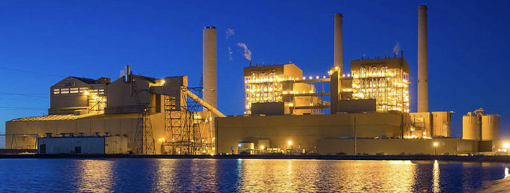
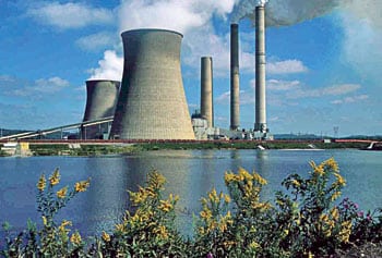
Power plants have invested hundreds of millions of dollars in equipment, and they annually spend millions of dollars to control emissions of particulates, SO2, and NOx. Yet the presence of very small amounts of SO3 can cause the stack plume to exhibit a visual discoloration that can extend for many miles (Figure 5). Elevated SO3 concentrations can even reduce the buoyancy of a plume to the extent that it touches down.
|
5. Before and after. The same Midwestern power plant before (top) and after installation of SBS Injection technology, in April 2005. Courtesy: Codan Development LLC
|

The effective removal of SO3 will eliminate several adverse health, environmental, and aesthetic consequences of sulfuric acid aerosol emissions and, in the process, produce significant O&M advantages for operators of coal-fired power plants. This strategy will benefit the public, electric utilities, and the coal industry by further reducing the environmental "footprint" of coal-fired power generation while simultaneously enhancing its efficiency and economics.
—Robert E. Moser is a principal and co founder of Codan Development LLC. He can be reached at fgdmoser@aol.com.