All power plant equipment has a limited lifetime, but not all components age at the same rate. Some equipment may outlast the useful life of a plant, while other machinery may be replaced more than once through the years. Boiler components offer a case in point. Typically, tubes exposed to higher temperatures and more extreme stress degrade faster. Understanding the mechanisms and knowing where to look for early warning signs could allow repairs to be made prior to failure.
If water chemistry control has been good, economizers usually last longer than radiant superheaters (SH) or reheaters (RH). The degradation process is caused by exposure to temperatures high enough for the materials of construction to operate in the creep range, for thermal fatigue to be a significant degradation mechanism, and, of course, for microstructural changes to develop.
For the purposes of this article, no wastage or wall thinning will be considered, that is, ignore fireside fuel ash corrosion, fly ash or sootblower erosion, and water/steam oxidation and corrosion. Wall thickness surveys will generally find those types of problems and tube replacements can be made as needed.
Concurrent with microstructural changes are decreases in hardness, strength, and ductility. Those changes include spheroidization of carbides in chromium-molybdenum (Cr-Mo) steels, graphitization in carbon (C) and C-Mo ferritic steels, and sigma phase formation and sensitization in austenitic stainless steels.
For high-temperature SH and RH outlet headers, creep and thermal fatigue interact in a unique fashion, often called creep fatigue, at the stub tube to header welds toward the ends of the headers. For headers with steam temperatures below the creep range, “simple” thermal fatigue may develop at these locations. Differential expansion between the hotter header and cooler waterwalls leads to a deflection of the “stub” tubes between the waterwalls and header. The “bending” or deflection is greatest at the ends of the header, assuming the expansion is symmetrical about the midpoint in length.
Creep Fatigue and Thermal Fatigue
The form of damage, creep fatigue or thermal fatigue, depends on the temperature of the individual stub tube. Microstructural analysis of the cracks is usually necessary to establish the cause. Not all tubes operate at the average steam temperature in the header. For individual tubes in an intermediate header, a steam temperature of 850F may be high enough for SA-213 T2 stub tubes to be in the creep range even though at 850F T2 is not usually expected to fail by creep at code-allowable stress levels.
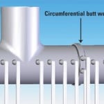
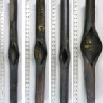
Estimates of the stresses imposed by differential expansion on the stub tube welds at or near the header may be calculated from simple beam theory. Assume the load on a flexible stub tube is a point at the waterwall/roof penetration, as shown in Figure 1.
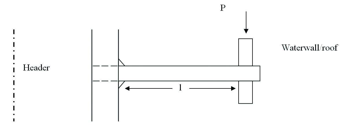 |
| 1. Stub tube example. Stresses imposed by differential expansion may be calculated from simple beam theory. Courtesy: David N. French Metallurgists |
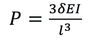
The deflection is given by:
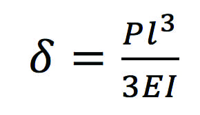
where δ is the deflection caused by the differential expansion (in.), l is the length of the stub tube between the header and waterwall (in.), E is Young’s Modulus (about 22 x 106 psi at 1,000F), I is the Moment of Inertia (in4) and for pipes and tubes is given by π / 64 x (outside diameter4 – inside diameter4), and P is the load necessary to cause the deflection (lb in simple bending).
The bending stress on the surface is given by:
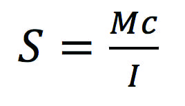
where S is the maximum stress in the outer fiber (psi), M is the bending moment (in-lb) and is equal to P x l (load x length), c is the distance from the neutral axis to the surface (in.), and I is the moment of inertia (in4).
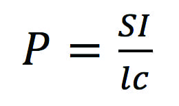
What is to be calculated is the stress, S, from the deflection at the cracked tubes near the ends of the header. The two equations can be solved for P as follows:
Setting the two equations equal to each other and then solving for S gives:
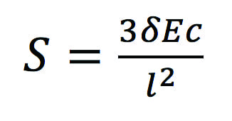
Perusal of the solution for S suggests the stress from differential expansion that causes creep fatigue or thermal fatigue damage, decreases as the stub tube gets longer (more flexible, less stiff), and increases as the deflection increases (longer header, larger temperature difference between waterwall and header) and stub tubes get larger in diameter.
The deflection is estimated from the differences in thermal expansion between the outlet header at 1,000F and the waterwall roof at 650F, hence:
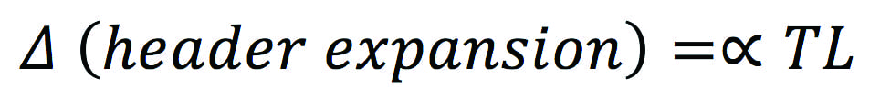
where ∝ is the coefficient of expansion (in./in./F), L is the length from header midpoint to end tubes (in.), ∝ for T22 from 70F to 1,000F is 7.97 x 10⁻⁶ in./in./F, ∝ for 210 A1 from 70F to 650F is 7.35 x 10⁻⁶ in./in./F.
This simple approach indicates where the first thorough inspection should be performed—tubes at the ends with the shortest length.
Cracking Case Study
The following example from the files of David N. French Metallurgists (DNFM) from a 33-year-old boiler illustrates some of these concepts. As a bonus, it provides an illustration of a true rarity, a dissimilar-metal weld (DMW) made with a nickel-based welding alloy that failed on the stainless steel side.
Inspection of the boiler’s high-temperature SH outlet header found significant cracks at the inner tubes of an eight-tube array (Figure 2). A close-up view of the damaged region is presented in Figure 3. Note the crack removal areas are in the smaller diameter tube and are on the half toward the end of the header.
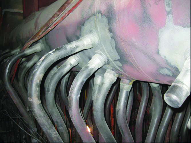 |
| 2. Superheater tube header. This image shows the end row of tubes in a 33-year-old boiler’s high-temperature superheater outlet header (grit blasted for ease of examination). The last pendant was removed at startup to balance steam temperature, and the capped tube on the right is part of that modification. Courtesy: David N. French Metallurgists |
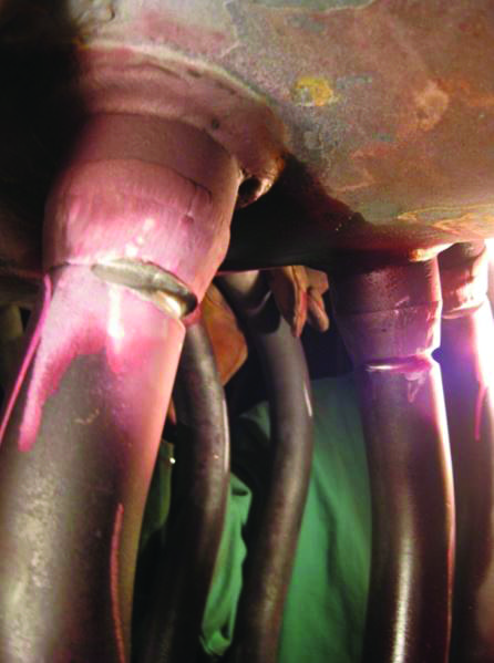 |
| 3. Cracking. This close-up shows the cracks prior to repair welding at the SA-213 TP321H stainless steel heat-affected zone. The cracks were in the wall of the tube that pointed to the end of the header. Courtesy: David N. French Metallurgists |
The deflection of the tube from differential expansion would put the tension portion of the tube facing the header end. The two tubes in this example were specified as 2.25-in. outside diameter (OD) x 0.460-in. minimum wall thickness (MWT) SA-213 T22 low-alloy steel and 1.75-in. OD x 0.260-in. MWT SA-213 TP321H stainless steel.
In practice, where damage occurs—SA-213 T22 at the header, T22 heat-affected zone (HAZ) of the DMW, or the 321 HAZ of the DMW—depends on several factors, including tube diameters, length to the roof (bending moment), shape of the DMW and T22 tube-to-header weld (stress raisers due to poor weld geometry), and the welding alloy used in the DMW. In most cases, the damage occurs at the DMW.
Dissimilar-Metal Welds
A DMW is a joint made between two different alloy systems, typically between ferritic and austenitic, or martensitic and austenitic. Historically DMWs were made with stainless steel welding alloys, often E-309. Failure would occur in the HAZ on the T22 side.
The coefficient of thermal expansion of stainless steel is about 30% larger than ferritic steels similar to T22. That difference placed a large thermal strain on the T22 at the edge of the fusion zone. The modern practice is to use a nickel-based alloy. Now the weld metal and T22 thermal expansion are nearly equal, and the thermal strain is transferred to the stainless steel HAZ. Under normal operation the stainless is strong enough to resist failure.
In the example presented here, the failure was in the TP321H. Because the tensile stresses are additive, the stress from bending of the stub tube due to differences in expansion between roof and header added to the stress in the HAZ caused by differences in expansion between TP321H and the weld metal. The result was failure in the smaller diameter TP321H tube as noted in Figure 3.
No dimensional measurements on header length or stub tube length were provided, so estimates of actual stress levels could not be calculated. The point may be moot, however, as stress relaxation would likely have occurred as the tubes operated at a high-enough temperature and long-enough times to effectively “stress relieve” the strains during service, which is likely the reason why the damage took so long to develop.
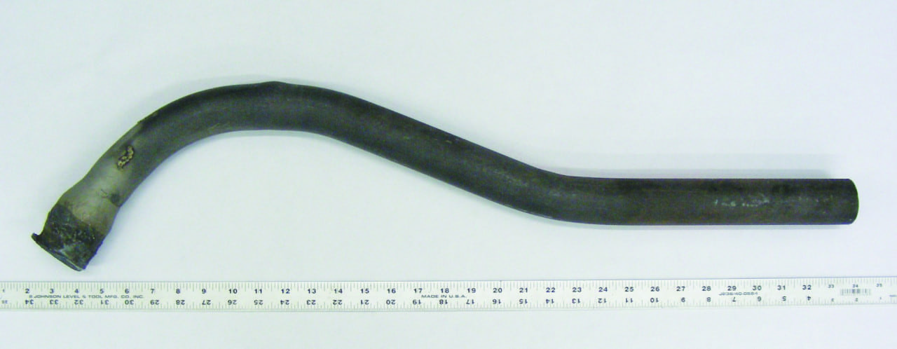 |
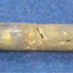
| 4. Test specimen. This image shows the as-received stub tube sample. Courtesy: David N. French Metallurgists |
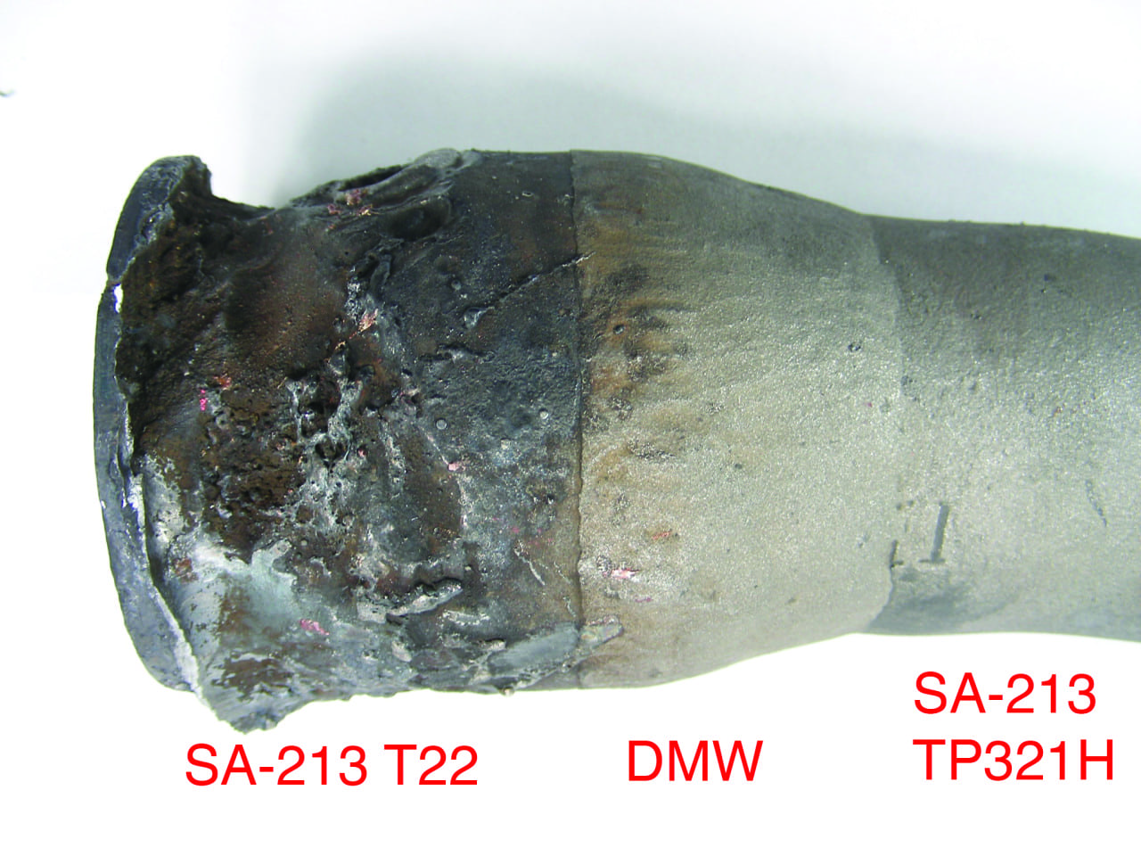 |
| 5. Smooth DMW. This close-up shows the dissimilar-metal weld (DMW) and T22 stub. Note the smooth transition by the weld between the 2.25-in. outside diameter (OD) T22 and the 1.75-in. OD TP321H. Courtesy: David N. French Metallurgists |
A second-row stub tube was sent to DNFM for metallurgical analysis and is shown in Figure 4. A close-up is presented in Figure 5. The DMW is well-made with a smooth transition between the tubes of differing diameters. Metallographic analysis of the DMW in a plane where damage, if any, was to be expected, displayed four interesting microstructural details. They were:
■ The microstructure of the TP321H was equiaxed austenite with the grain boundaries decorated with both carbides and sigma phase (Figure 6). The appearance of sigma phase suggests this pendant or several end pendants may have operated above the design temperature for a fair portion of the 33-year service. It may also imply a U-shape to the temperature distribution within the superheater (other pendants would have to be examined to confirm this).
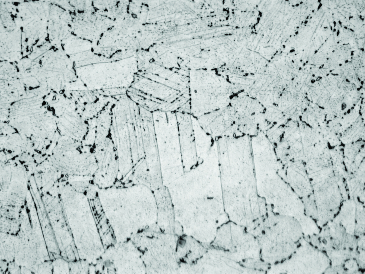 |
| 6. Carbides and sigma phase. The microstructure of the TP321H was austenite, as expected. The grain boundaries were well covered with both carbides (sensitized) and sigma phase—the larger black spots on the grain boundaries. Courtesy: David N. French Metallurgists |
■ At the OD next to the weld metal HAZ, the expected intergranular creep or creep-fatigue cracks (Figure 7) were found. This was the result of the combined tensile stresses from bending and the DMW.
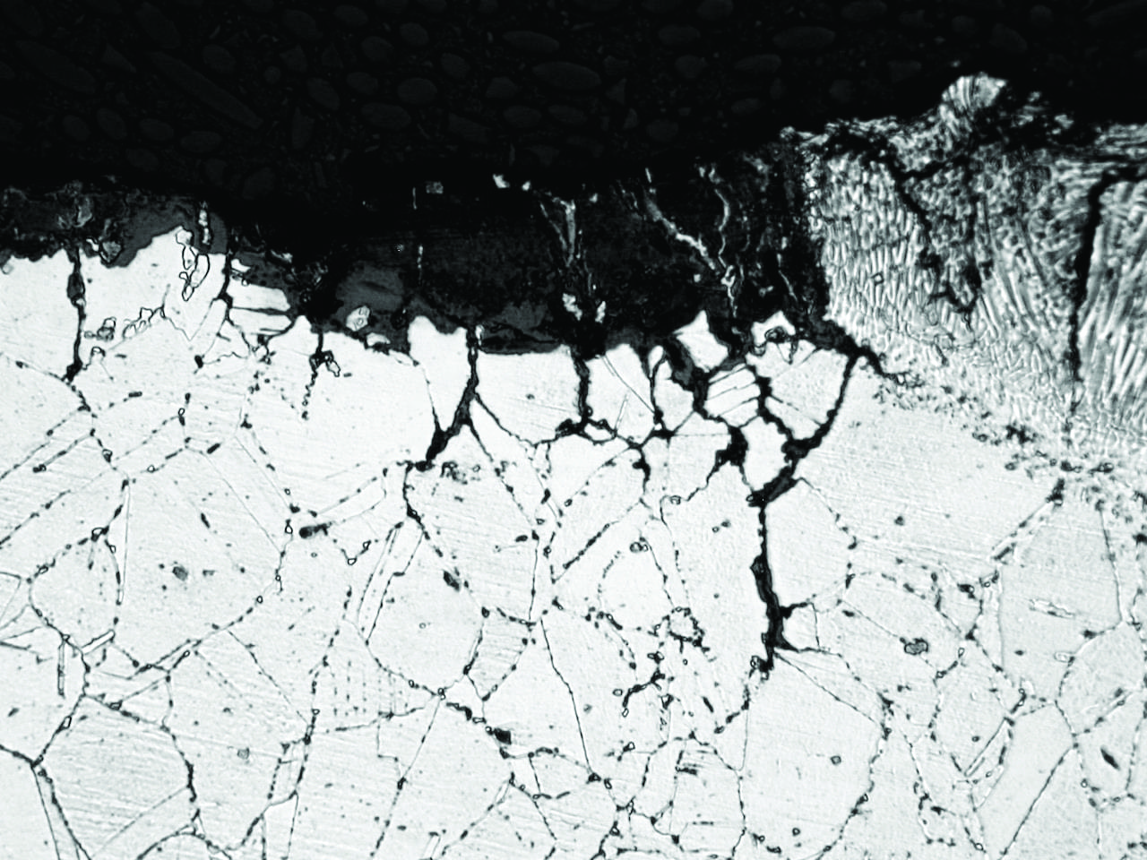 |
| 7. Creep. The OD at the toe of the DMW contained the early stages of creep or creep-fatigue damage—the intergranular cracks. Note the thinning in some austenite grains, indicative of plastic strain. Courtesy: David N. French Metallurgists |
■ Also noted near the cracks were twin boundaries—the straight black lines across some austenite grains—evidence of plastic strain from the tensile stresses.
■ A small step or change in diameter, a stress raiser or “notch,” at the edge of the weld metal. The TP321H oxidizes more rapidly than the nickel weld metal (similar in composition to Inconel 625). Over the service life, the stress raiser further increases the effective tensile stress.
In summary, the damage in stub tube-to-header welds as a result of differential expansion between header and roof may be explained by stresses estimated from simple beam theory, expected operating stresses on weld alloys, and conditions used during fabrication. More important, however, is the help provided in knowing just where to look for the first signs of damage—the precursor to failure—as steam generators pass the 25-year mark. The careful inspection required to find these cracks requires thorough cleaning, which is time consuming. Such inspection techniques as liquid penetrant, magnetic particle, and replications are recommended. ■
—Rama S. Koripelli, PhD, PE (rkoripelli@davidnfrench.com) is the technical director for David N. French Metallurgists, and David N. French, ScD (dfrench@davidnfrench.com) is the founder of David N. French Metallurgists.