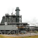
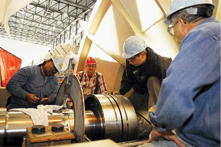
Port Washington Generating Station (PWGS) is two for two. Phase 1, placed into commercial service in July 2005, was a POWER Top Plant. So, too, is Phase 2, the second 545-MW power block of We Energies’ PWGS, located on the shore of Lake Michigan. Phase 2, which entered commercial service on May 23, 2008, after successfully completing its final testing activities, effectively doubles the plant’s output to 1,090 MW (Figure 1).
1. Siamese twins. Unit 2 of the Port Washington Generating Station rises next to Unit 1, which was completed by URS Washington Division’s Wisconsin Power Constructors in 2005. Phase 2, using a virtually identical design, entered commercial service in May this year. Courtesy: URS Washington Division
“[The completion of Unit 2] is a major part of our investment in upgrading the energy infrastructure of the region,” said Rick Kuester, executive vice president of Wisconsin Energy Corp., the parent of We Energies. “The Port Washington units are a cornerstone of our effort to provide the energy our customers need now and in the decades ahead.”
The PWGS, located 25 miles north of Milwaukee, replaces the original station on that site. The historic station, built in 1935 directly adjacent to Lake Michigan, consisted of five pulverized coal-fired units, each of 80-MW capacity. Those units held the world’s heat rate record from 1935 to 1948.
PWGS is an intermediate-load combined-cycle plant built under provisions of Wisconsin’s unique Leased Generation Law, enacted in 2001. The Wisconsin State Legislature decided that a non-utility generation company (such as We Power LLC, a unit of Wisconsin Energy) may build and own new generating units in the state but may not operate them. PWGS Phase 1 was the first plant built under the law’s provision that utilities can lease power plants from an unregulated affiliate. It also was the first plant completed as part of Wisconsin Energy’s Power the Future (PTF) plan. PTF was announced in September 2000 as a comprehensive approach to address electricity supply and reliability issues for We Eneries’ customers in Wisconsin and Michigan’s Upper Peninsula. When complete in 2010, PTF is expected to add approximately 2,300 MW of power generation in the We Energies service area.
Proven prime mover
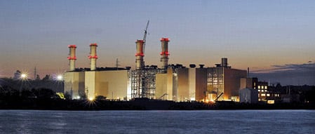
Phase 2 of this project is a gas-fired combined-cycle plant powered by two General Electric 207FA gas turbines, each exhausting into a three-pressure heat-recovery steam generator (HRSG) with supplemental duct firing supplied by Alstom Power Inc. The HRSGs’ main steam conditions are 2,000 psig and 1,055F. Each HRSG supplies steam to a single D11 three-pressure, reheat, dual-downward-exhaust-flow steam turbine also supplied by GE (Figure 2). Steam condensing occurs via a single-pass, divided-waterbox condenser using lake water for once-through cooling. Steam jet air ejectors maintain condenser vacuum. The cost of the entire plant was approximately $669 million.
2. Building power blocks. Work under way on the gas turbine enclosure and the heat-recovery steam generator inlet duct. A circulating water pump is pictured in the foreground. Note that the building enclosure was completed prior to winter weather setting in. Courtesy: URS Washington Division
Hot-day performance of the combustion turbines is enhanced by inlet air-cooling using lake water as the cooling medium. The chiller coils kick in whenever the lake temperature is five degrees cooler than ambient air temperature–unless the lake water temperature drops below 40F, in which case the chillers automatically throttle off. Hot-day capacity for each power block is 500 MW unfired and 545 MW in the supplemental firing mode. Fuel is solely natural gas, delivered at the combustion turbine operating pressure of 500 psig.
Learn from experience
In 2006, We Power awarded Wisconsin Power Constructor (WPC), a subsidiary of the Washington Division of URS Corp., a contract to construct the Phase 2 addition to PWGS. URS Washington Division also provided engineering and procurement services. Table 1 lists the suppliers of Phase 2’s major systems and equipment.

Key suppliers of equipment and services to the Port Washington Generating Project. Source: URS Washington Division
Work was performed under an innovative open-book, shared-risk contract that required We Power and WPC to work together cooperatively and share project rewards and risks. Under terms of the contract, work was handled by a completely integrated project team consisting of employees from both companies. In some instances, WPC employees reported to We Power managers; in other cases, We Power employees reported to WPC managers. This approach, coupled with a committed Milwaukee-area workforce, paid off: In addition to its excellent safety record, the project enjoyed overall better-than-anticipated craft productivity. The building trades workers in the Milwaukee area were fully committed to the project. Workers had an extremely high skill level and positive attitude, worked hard, and took pride in their work.
This second phase of the project was designed to build on the success of the first phase. The same team responsible for building Phase 1 was tasked with building the identical Phase 2. New team members could easily see the first phase’s finished product by walking next door to the operating plant.
Numerous economies resulted from constructing an identical project using essentially the same management team, especially the same craft general foremen.
By the end of Phase 2, the project had used approximately 10% fewer craft man-hours than Phase 1 had three years earlier. The schedules were comparable, and each phase required approximately 26 months to complete. Work schedules were also similar: five 10-hour days plus eight hours overtime per week. Phase 2, unlike Phase 1, required no second-shift work to complete construction before the scheduled May completion date. Overtime was necessary to attract qualified craft labor that has plenty of heavy construction work opportunities these days.
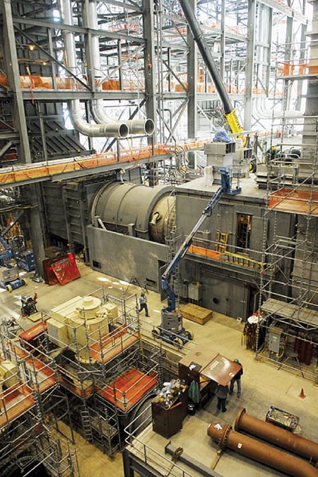
Generally speaking, the craft and labor savings correlated with the project’s peak labor needs: 550 workers for Phase 1 compared with only 400 workers for Phase 2–a key indicator of the quality of the craft supervision on the project (Figure 3). Having a complete set of construction drawings available before turning over the first shovel of dirt also helped.
3. The straight and narrow. Millwrights (blue hardhats) and an ironworker (red hardhat) work on alignment of the steam turbine. Courtesy: URS Washington Division
PWGS Phase 2 was not immune from the challenges of attracting workers with journeyman credentials–a common difficulty cited by contractors these days. WPC ultimately hired 400 pipefitters over the length of the project to fill 120 open jobs. Most of the pipefitters, and other qualified craft workers, were “travelers”–workers who follow projects that often are far from home, so they look for employment opportunities with overtime.
Split the costs
Commercial terms for the design and engineering of Phase 2 were similar to those of Phase 1 but reflected the knowledge gained by the team on the first project. Without getting into the contracting details, the target price, cost-reimbursable contracts were crafted to provide incentives for all project participants.
The scope of work for WPC and We Energies was determined with target costs set for each that included engineering, start-up management, field engineering, craft labor, and the like. In general, a target price was calculated less the price of major equipment purchases made by the owner. The We Energies side of the ledger included project subcontracts and related labor in order to save the WPC fee and general and administrative charges, although URS Washington Division supported We Energies by negotiating and preparing purchase orders.
Finally, the target costs of WPC and We Energies were summed to determine the overall project target price. Costs that exceed or are less than the target prices will be shared by the team under a set of formulas set out in the contract. Although the final tally wasn’t complete as this article was prepared in August, the unofficial word was that the project cost was within a million dollars of the $325 million target estimate for Phase 2. This is a remarkable achievement even if you consider the steep rise in commodity prices alone since Phase 1 was completed in 2005.
PWGS now has a very reliable, state-of-the-art, fully enclosed combined-cycle plant for less than $650/kW at a time when new plants of like capacity would cost perhaps a billion dollars.
Build it right
The plant’s historic and unique location near the town required designers to incorporate portions of existing buildings into the new plant for aesthetic reasons and to satisfy permitting authorities. Other important environmental design criteria for the project included those discussed below.
Minimize visual impact. The original concrete and red brick station was praised for its design, and its integrity was maintained through subsequent additions. In 1980, the American Society of Mechanical Engineers designated it a National Historic Mechanical Engineering Landmark. With the technology conversion, it was decided to retain the north and west walls of the structure, hide the new air intakes behind the west wall, and only build out to the south and east, leaving the facade facing Port Washington unchanged.
This decision, coupled with the requirement to use existing intake and discharge tunnels for the circulating water system, presented significant engineering challenges. Washington Division used 70-year-old drawings to develop a 3-D model for a plant background. By locating new components on this background, and by locating the combustion turbine air intakes on the roof, the plant fit into the building.
For Phase 2 construction, the plant was boxed in on three sides–north, west, and south, where the operating plant sits; the only access is from the east side. This constraint posed a considerable challenge and required extensive planning to successfully coordinate a construction effort that entailed building from west to east. Tower cranes were used during the early stages to help with the complicated hook plan.
Maintain thermal discharge limits. The original station had employed once-through cooling, and for both units of the new station to operate under the original water use permits, the intake and discharge apparatus could not be modified. The historical total water flow and temperature rise were used as the plant design basis, which dictated the combined two-power block capacity of 1,090 MW.
Using combustion turbine technology in an efficient combined-cycle operating mode, the two new unis will produce over 2.5 times as much electricity as the original station while consuming less than half the fuel per kilowatt-hour–without increasing thermal discharge.
Traveling screens were fit into the existing concrete wells. Removing cladophora moss (green algae found in Northern Hemisphere lakes) required an innovative, dual-wash system, although discharge had to exit through the original discharge box. During normal operation, the screens travel at 5 feet per minute and are washed by a series of low-pressure nozzles. If moss build-up is detected, the system automatically switches to a screen speed of 20 feet per minute and starts a high-pressure booster pump. Separate high-pressure nozzles remove moss before it causes total system blockage.
The existing intake and discharge tunnels were not modified, but separate circulating water pump chambers were constructed adjacent to the original intake chamber. Due to the larger pump size, the floor of the new chambers is significantly below lake level. An extensive cofferdam and grouting system prevented flooding during construction. When the chambers were completed, the original intake tunnel was dewatered and the wall between the tunnel and the intake chambers was removed.
Because the new condenser is above lake level, a seal-well system and mechanical vacuum priming system are continuously operated to remove residual air and ensure that the condenser tubes contain cooling water.
Tie-in of the circulating water basin into the existing tunnel had to be performed in a short, three-week period. Because the operating unit was downstream of the tie-in point, the complicated tie-in had to be performed during an outage so that it wouldn’t impact the other unit’s operating schedule.
Reduce noise and air emissions. The level of noise control used on this project was determined by the proximity of residences and the city’s requirement that sound levels not exceed existing levels. The new power house building and equipment inside it employ various noise-attenuation features.
The gas turbine air inlet and HRSG stack incorporate additional sound baffling. Special attention was given to the penetrations for HVAC fans and vents, and safety valves were fitted with silencers. Furthermore, the new building uses precast concrete panels and insulated steel siding, and its exterior treatment minimizes the escape of sound. The plant was also enclosed within a building, walls were acoustically treated, and the number of doors and windows was minimized.
Best available control technology (BACT) and the latest pollution control includes dry, low-NOx combustors and catalytic converters in the boilers to minimize emissions of NOx, CO, and volatile organic compounds (VOC). NOx removal catalysts in each HRSG use 19% aqueous ammonia injection. A CO catalyst is also installed in each HRSG. The station meets both national and state air emission requirements.
Control flood water and protect the environment. An overgrown creek running through the property did not carry rainwater away quickly, but due to ecological concerns, the creek bed could not be cleared. Instead, a permanent flood diversion channel was constructed to carry rainwater to Lake Michigan before it could overwhelm the creek. To permit creek water flow, the flood diversion channel was constructed with a weir wall, carrying away excess water (Figure 4).

4. Fooling floods. As part of the plant’s comprehensive environmental protection plan, a permanent flood diversion channel was constructed around the plant to carry rainwater to Lake Michigan to prevent it from overwhelming the creek. Courtesy: URS Washington Division
A comprehensive plan was implemented to prevent erosion and storm water runoff from carrying debris into Lake Michigan. Building floor drain contents are sent directly through an oil/water separator before being mixed with the circulating water for discharge into Lake Michigan.
Several protected species were identified. For example, the original station’s north stack had been home to a peregrine falcon nest box for almost a decade. In 2000 a pair of peregrines successfully fledged young there. After nesting season, the box was relocated to the new structure, and the falcons returned and reared young during construction.
Take proactive safety measures
Safety in all phases of the plant design and construction was among the factors that made the PWGS Phase 2 project exemplary. The project team implemented safety performance lessons learned from constructing Phase 1 to further improve safety performance during construction of Phase 2.
By April 2008 project workers had completed more than 2.5 million hours without a lost-day injury and earned one of the U.S. Occupational Safety and Health Administration’s (OSHA) highest safety honors–Star Status in OSHA’s Voluntary Protection Program (VPP).
According to OSHA, the purpose of the VPP program is to establish cooperative relationships between management, labor, and OSHA that bring “together company managers, employees, union representatives, and OSHA in a proactive, cooperative effort to implement and model outstanding safety and health management systems.” Since the program’s inauguration in 1982, more than 2,000 participants have been recognized as VPP Star worksites (Figure 5). Only a few achieve Star Status for their “exemplary worksites with comprehensive, successful safety and health management systems.”
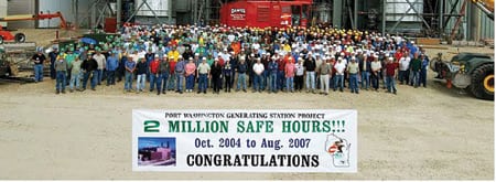
5. Star Power. WPC was presented with OSHA’s Voluntary Protection Program Star Status flag in October 2007. The project also achieved more than 2.5 million hours (by April 2008) without a lost day of work accident. Courtesy: URS Washington Division
There are many reasons why the workforce achieved such significant safety milestones. Chief among them has been the tight customer and contractor team, especially where project safety was concerned. WPC brought the industry-leading safety culture of Washington Division to the project, and the staff of superintendents and engineers promoted the safety culture and ensured that safety was integrated into all work processes. This attitude was bolstered by the efforts of cooperative and safety-conscious craft workers, an extensive safety training and mentoring program, and a safety process that enables supervisors to recognize and correct “at risk” acts before injuries occur.
This project illustrates Washington Division’s philosophy, which values people as its most important resource and makes their safety its first priority. Accordingly, treating people with respect and putting safety first creates a successful safety culture. In addition, because many members of the project team worked on construction of PWGS’s Phase 1, the safety culture change that began to develop during the first phase was accepted by much of the workforce at the very beginning of the second phase.
Additionally, 90% of the WPC Port Washington construction staff–including managers, superintendents, engineers, project controls staff, client resident managers, and all We Power and PWGS employees–have achieved Safety Trained Supervisor certification.
Be a good neighbor
The plant is adjacent to downtown historic Port Washington on the west and on the beach of Lake Michigan on the east. There’s a large bluff to the south and a busy marina to the north. During construction of both phases, the project team had to work within the limitations of a very compact construction site.
Work was scheduled and performed to ensure that the station remained a good neighbor and to minimize negative impacts on its surroundings. Night shift work was limited to indoor activities, temporary construction lighting was pointed away from downtown, and construction traffic was directed away from the city. To further minimize construction traffic, some of the larger boiler components were delivered by large oceangoing ships, which–as the largest ships to enter Port Washington harbor–were the talk of the town (Figure 6).

6. Quick delivery. The power plant’s location on the shore of Lake Michigan allowed freighters to deliver large components directly to the construction site. Courtesy: URS Washington Division
Those efforts paid off when the city recognized the project’s contribution to the community by giving it the Chamber of Commerce Business of the Year award for 2007.