 |
| Courtesy: Energy Concepts Co. |
The LM6000 is the most widely used aeroderivative combustion turbine (CT) in the world, with more than 1,000 installations. As with all CTs, power output and heat rate degrade markedly during warm weather. The ARCTIC (Absorption Refrigeration Cycle Turbine Inlet Conditioning) system eliminates this deficiency.
The power rating and heat rate of all combustion turbines (CTs) degrade with increasing ambient temperature. Unfortunately, in most regions, the warmest weather (daily and yearly) is coincident with the greatest demand for electricity and is the exact time when CT performance plunges.
A good example of the warm weather performance effect is the PC SPRINT model of General Electric’s LM6000. This CT produces 51.3 MW at a heat rate of 8,488 Btu/kWh when the ambient temperature is 48F. But when the temperature rises to 100F, the CT output dips to 38.5 MW and heat rate degrades (increases) by over 6%. This degradation is the primary reason why many CTs in warm weather service have some means of conditioning the inlet air.
New Air Inlet Cooling Option
Historically, there have been two primary options for inlet air chilling: evaporative cooling (spray or wetted media) and mechanical compression. At 100F ambient temperature, evaporative cooling increases the LM6000 output to 44.6 MW (dependent upon humidity), with 2% degradation in heat rate (compared to the heat rate at 48F). Mechanical compression chilling of the inlet air to 48F increases the output to 49 MW net, but the heat rate degradation increases to 5%. For this discussion, net output includes chilling parasitic load but excludes other plant parasitic loads.
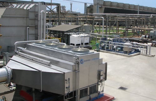
A third option has now proven its worth in long-term operation. The Absorption Refrigeration Cycle Turbine Inlet Conditioning (ARCTIC) system—developed by Energy Concepts Co., with team members Kiewit Power Engineers and Nooter/Eriksen—uses an exhaust heat–powered inlet air-conditioning system (Figure 1). With ARCTIC, the net output of the LM6000 on the same 100F day increases to 51 MW, with no heat rate degradation. The performance gain comes from using exhaust heat to produce the necessary chilling, thus avoiding the roughly 2 MW parasitic penalty of mechanical compression (based on a 2,000-ton centrifugal chiller). Figure 2 illustrates the performance gains achieved with and without using ARCTIC on an LM6000 PC SPRINT.
 |
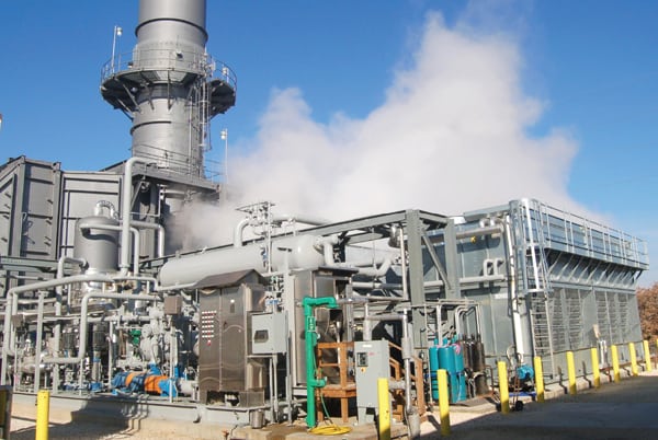
| 1. New inlet air-cooling option. An LM6000 PC SPRINT combustion turbine with ARCTIC has completed three summers of operation in central Texas. The ARCTIC system is designed to operate in tandem with the remote start of the LM6000. Courtesy: Energy Concepts Co. |
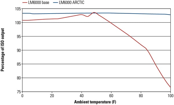 |
| 2. Flat-line performance. The ARCTIC-equipped LM6000 PC SPRINT with NOx water injection is shown as a percentage of ISO output across a range of ambient temperatures. The SPRINT version of the LM6000 also uses water injection into the high-pressure and low-pressure compressors to produce an additional 3.5 MW across all ambient temperatures. Source: Kiewit Power Engineers |
An LM6000 PC SPRINT with ARCTIC system installed at a central Texas utility has demonstrated this capability nearly every day for the past three summers, operating for 2 to 12 hours per day, in response to market conditions. The system requires no operators and functions fully automatically by matching the CT’s 10-minute start to full-load power sequence. When the CT shuts down, ARCTIC automatically shuts down after a short cool-down period.
There were approximately 400 starts of the LM6000 during a three-year demonstration period of the ARCTIC system. During this demonstration, the ARCTIC automatic start sequence failed only five times, producing a start reliability of nearly 99%. Importantly, failed starts were all nonrecurring failures. In each case of a failed ARCTIC start, the CT start and operation continued without interruption. The LM6000 merely operated without the warm weather performance enhancement.
The ammonia-water absorbent of the ARCTIC system passes through a heat exchanger inserted in the CT exhaust gas, producing 2,000 tons of chilling while also cooling the CT exhaust gas from 840F to 720F. Remarkably, the lower exhaust temperature is also the ideal operating temperature for the selective catalytic reduction (SCR) catalyst for maximum catalytic activity and catalyst life. The heat exchanger added to the exhaust path adds roughly 0.6 inches water column to the exhaust pressure drop. This added pressure drop is actually less than the exhaust pressure drop caused when adding tempering air fans to reduce the CT exhaust temperature to match the SCR temperature needs while also eliminating the added parasitic electric load of the tempering air fans.
Industrial CTs (such as the General Electric Frame 7FA) also benefit from exhaust-powered inlet air chilling. These CTs typically have a lower compression ratio, and hence have more excess air than aeroderivative turbines. As a result, they derive a somewhat lower power gain from chilling, about 4.5 kW/ton of chilling instead of the 5.0 kW/ton enjoyed by the LM6000. However, when the frame turbine is used in combined cycle mode, the power gain from inlet air chilling increases to more than 5.5 kW/ton.
The ARCTIC mode of operation is more advantageous than duct firing because it restores the warm day power to the CT’s standard rating, but without the heat rate penalties of duct firing. Duct firing can still be used when peak power is required. Inlet chilling of combined cycles can further increase cycle efficiency by preheating feedwater using the ARCTIC system reject heat, further improving the combined cycle efficiency.
Normally, the chiller rating is selected only for chilling the inlet air. However, sufficient heat energy remains in the exhaust after the SCR to produce several thousand tons of additional chilling for other applications, such as chilled water storage, cooling electric generators, lube oil systems, or any other systems adversely affected by hot weather.
ARCTIC Operation
The component parts of the ARCTIC system are illustrated in Figure 3. The evaporative condenser and the turbine inlet air chiller (TIAC) perform essentially identical functions as their mechanical compression counterparts. The wet surface air cooler (WSAC) was selected for the demonstration plant because of superior performance, but it does required 40 gpm of makeup water at design conditions. (For more information on WSACs, see “Wet Surface Air Coolers Minimize Water Use by Maximizing Heat Transfer Efficiency” in the September 2008 issue at https://www.powermag.com.)
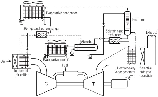 |
| 3. ARCTIC flow diagram. In general, waste heat from the combustion turbine (CT) exhaust is used in an absorption chilling system to cool the CT’s inlet air. The ARCTIC system is designed to produce sufficient chilling to maintain a constant power output, with little change in system efficiency, across a wide temperature range. Source: Energy Concepts Co. |
The total design requirement for makeup cooling water for the ARCTIC system plant is 125 gpm. However, the inlet air chilling is well below the wet bulb temperature, so there is a steady stream of almost pure condensate recovered, about 25 gpm at design conditions. In locations where water is scarce, air-cooling is another option. The performance gain relative to mechanical compression is even greater when air-cooled because air-cooled mechanical compressors require more parasitic power to operate. The air-cooled variant of this system has been designed to operate at ambient temperatures up to 125F.
The TIAC can be chilled by a circulating coolant (water or glycol) or by direct expansion of refrigerant. The latter was selected for the demonstration plant, avoiding the 80-kW parasitic load of the coolant pumps. Chilled ammonia is expanded and distributed into the TIAC coils at 34F.
The refrigerant heat exchanger (RHX) is equivalent to the suction line heat exchanger (SLHX) found in some mechanical compression units for efficiency improvement. The RHX improves the coefficient of performance (COP), the efficiency of the refrigeration unit, by nearly 10%. The resulting ARCTIC COP is a very attractive 0.6, where each unit of exhaust heat input yields 0.6 units of chilling output.
The remaining ARCTIC components—heat recovery vapor generator (HRVG), rectifier, cooler, absorber, and solution heat exchanger (SHX)—are responsible for compressing the low-pressure vapor from the TIAC to produce high-pressure vapor for the condenser. The function is synonymous with the electric-powered compressor of the mechanical vapor compression system. The low-pressure ammonia vapor is next absorbed into the aqueous ammonia absorbent located in the absorber. The cooler keeps the absorber at low temperature to allow absorption to proceed.
The absorbed solution is next pumped to higher pressure and recuperatively heated in the SHX before being desorbed by exhaust heat in the HRVG, at the high-side pressure of 230 psig. A solution pump pressurizes the solution from low-side pressure (50 psig) up to 230 psig. The 60-kW solution pump (shown below the absorber in Figure 3) is the primary electric demand of the cycle, with the evaporative cooler fans. The equivalent mechanical compressor system requires 2,000 kW.
Next, the desorbed vapor has approximately 10% water vapor, which is reduced to less than 2% in the rectifier. The non-adiabatic rectification eliminates the need for separate reflux or reboil, thus minimizing any penalty to cycle efficiency. Physically, the rectifier is a 5-foot-diameter column with seven non-adiabatic distillation trays. Each tray has about 180 square feet of heat exchange surface.
The ammonia inventory in the 2,000-ton ARCTIC is approximately 6,000 pounds. Most cold storage warehouses and food processors have similar or larger ammonia inventories. However, there are notable differences. The ARCTIC ammonia is diluted with about 8,000 pounds of water, and it contains no oil, making the solution appreciably less hazardous than anhydrous ammonia used in the SCR.
Winter peaks in electric demand also occur in the region where the demonstration plant is located. When the ambient temperature is below 40F and the air is humid, the LM6000 requires the inlet air to be heated at least 10F to avoid icing in the bellmouth or on the low-pressure compressor stationary vanes. The ARCTIC system has an anti-icing mode in which it heats the inlet air by 20F to eliminate inlet icing. The transition between heating mode and chilling mode is automatic. This mode of operation was demonstrated multiple times each winter (and on exceptionally cold spring and fall days).
The robustness of ARCTIC was demonstrated by its reliable operation during exceptionally harsh test conditions, such as during ambient temperatures from 110F down to 11F, multiple starts and stops per day, and frequent, rapid power cycling from minimum to maximum output. In one notable episode, temperatures in central Texas dropped to a record-setting 11F. Several large power plants were knocked offline, causing critical power supply shortages. The ARCTIC LM6000 operated for 62 continuous hours until the emergency passed.
The ARCTIC is delivered as a skidded unit (Figure 4). For utility applications, the standard skid sizes are 2,000 tons and 3,000 tons of inlet chilling. For smaller turbines (less than 20 MW) a range of skid sizes is available, from 100 to 1,000 tons.
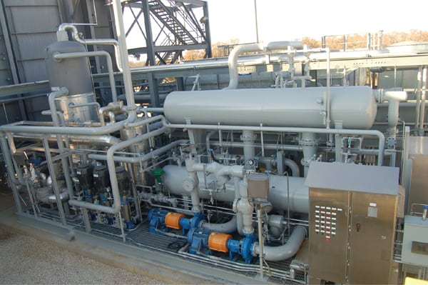 |
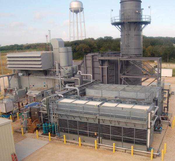
| 4. ARCTIC equipment. The ARCTIC system is packaged onto a single skid to enable quick field installation and ease of interconnection with the LM6000 PC SPRINT. Courtesy: Energy Concepts Co. |
The ARCTIC system has a small cost premium relative to a mechanical chiller of the same capacity. However, when all the auxiliary functions are credited (anti-icing, tempering air, less switchgear), the overall installed cost is essentially the same. The system’s big plus is the increased cold- and hot-weather performance, improved operating efficiency, and reduced maintenance relative to a plant using a mechanical chiller for inlet cooling, all obtained at no additional cost.
— Donald C. Erickson (enerconcep@aol.com) is president and Ellen E. Makar is the project’s engineer for Energy Concepts Co., the ammonia absorption refrigeration technology supplier. The authors wish to acknowledge the other members of the team that developed the utility-scale ARCTIC: Kiewit Power Engineers’ Chris Mieckowski, responsible for project implementation, and Nooter/Eriksen, supplier of the heat recovery vapor generator.