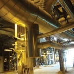
In a typical steam power plant, the boiler feedwater (BFW) pump takes suction from the deaerator (DA) and discharges high-pressure water to the boiler through the feedwater heaters. During normal operation, the DA is supplied with steam turbine extraction steam to mix with and heat the feedwater. Other purposes for the DA are to provide the required net positive suction head (NPSH) for the BFW pump and to serve as a storage tank to ensure a continuous supply of feedwater during rapid changes in BFW demand (Figure 1).
1. Circumventing cavitation. The available net positive suction head provided to a boiler feedwater pump can drop enough during a pressure excursion to cause cavitation and damage to the pump’s internal parts. A careful analysis of various operating profiles can ensure that the pump operates safely during the pressure fluctuations that occur after a steam turbine trip or large load change. Courtesy: PGESCo., Egypt
How does the plant designer or operator determine the adequacy of the BFW pump selection or the DA and feedwater system design? It’s not uncommon to find that the BFW pump was originally specified based on steady-state conditions and did not consider the DA pressure transients that occur during a steam turbine trip (with the boiler remaining in service) or a sudden steam turbine load reduction. If the NPSH available to the BFW pump during the pressure transient drops below that required by the pump for only a short period of time, cavitation and damage to the pump internals often result.
An NPSH deficit in an existing system or a new system under development can be avoided by using some very simple analytic tools.
Find the NPSH margin
The deaerator is installed at some elevation above the BFW pump to provide the NPSH required by the pump. By definition, the NPSHr is the total suction head over and above the vapor pressure of the liquid pumped.
The DA elevation minus the dynamic losses in the BFW suction piping between the DA and the BFW pump equals the NPSH available (NPSHa) to the pump. The difference between the value of the NPSHa and that required (NPSHr) by the pump gives the NPSH margin.
The NPSH margin or the NPSH margin ratio (NPSHa/NPSHr) is an important factor in ensuring adequate service life of the pump and minimizing noise, vibration, cavitation, and seal damage. The NPSH margin requirement increases as the suction energy level (for example, high suction specific speed, high peripheral velocity of impeller, and the like) of the pump increases. In the case of the BFW pump, this ratio could be in the range of 1.8 to 2.5. These margins are typically based on steady-state operation.
In addition, the NPSH margin improves the ability of the BFW pump to handle a DA pressure transient. Once a design is determined to have an adequate NPSH margin, the next step is to determine if the NPSH margin is adequate during a pressure transient.
Expect Deaerator Pressure Decay
Immediately after a steam turbine generator trip, turbine extraction steam is no longer available to the deaerator, resulting in decay of the DA pressure. Also during a sudden steam turbine generator load reduction, the extraction steam pressure decreases until the extraction stage supplying the DA can no longer maintain DA pressure. This also results in DA pressure decay as the lower-temperature condensate continues to enter the DA, cooling the stored feedwater.
The decrease in DA pressure causes some of the water in the DA storage tank to flash to steam until saturation pressure is reached at the new DA pressure. The water in the BFW pump suction line has a static head exerted on it by the level in the DA storage tank, preventing it from flashing immediately. Therefore, the water in the suction line can be considered as a slug of hot fluid that must be moved through the pump in some finite amount of time. In other words, the pump will not perceive a decrease in vapor pressure (or a decrease in water temperature) until the entire slug of hot water has passed through the pump.
During the passage of the hot-water slug, the combination of high vapor pressure at the pump suction along with a decrease in pump suction pressure (due to DA pressure decay), results in a "critical point" at which the suction pressure may drop below the minimum required pressure (that is, the vapor pressure of the hot-water slug plus the pressure equivalent of the NPSHr). This low suction pressure could result in cavitation damage to the pump internals due to insufficient net positive suction head.
Short Residence Time
The time required for passage of the hot-water slug through the pump suction line is the "residence time." Residence time can be expressed as the suction line volume divided by the volumetric flow rate (or, alternatively, as the mass of liquid in the suction line divided by the mass flow rate).
Note that because the vapor pressure at pump suction is modeled to decay only after the residence time has elapsed, the critical point occurs at the end of the residence time interval. The challenge is to determine the DA pressure at this critical point and thereby the system NPSH margin.
Establishing the Deaerator Pressure Decay Curve
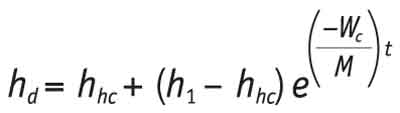
A simplified way to express the DA pressure decay is by the exponential decay equation for enthalpy. In addition, the corresponding DA pressure at any time is the saturation pressure at the calculated DA water enthalpy:
where,
hd = enthalpy of deaerator water storage tank at any time t, Btu/lb
hhc = enthalpy of condensate in condenser hotwell, Btu/lb
h1 = initial enthalpy of deaerator water storage tank, Btu/lb
Wc = condensate flow after steam cut-off, lb/min
M = mass of water in deaerator storage tank, lb
The actual pressure at BFW pump suction is simply the DA vapor pressure as computed by the equation plus the DA static head less the frictional pressure drop in the BFW pump suction piping.
This equation conservatively models the system well but does not consider the warm condensate contained in the low-pressure (LP) heaters and the condensate piping.
If using the equation on your system indicates a problem with the BFW pumps’ capability in handling the DA transient, you may want to recheck the calculations using the more exact equations available in this reference source: Liao, C.S., and Leung, P., "Analysis of Feedwater Pump Suction Pressure Decay," ASME Journal of Engineering for Power (April 1972). However, the approach described in this article uses a more conservative approach to the calculations.
Note that the condensate flow to the deaerator (Wc) after steam cut-off must be established correctly based on subsequent boiler load and spray water consumption in the steam attemperators. The boiler load is also assumed to be limited to the capacity of the turbine bypass system.
Establish Critical Point Margin
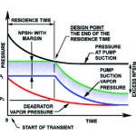
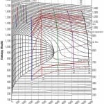
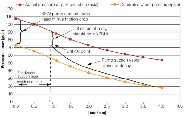
Figure 2 shows a plot of the actual measured pressure at the BFW pump suction and the DA vapor pressure for a typical steam power plant. The difference is the available NPSHa at the pump inlet. Also note that during the DA pressure transient, the actual pressure at pump suction decreases as the DA vapor pressure decays for almost a full minute. However, due to the time it takes for this hot-water slug in the pump suction line to pass, the pump suction vapor pressure does not decrease until after the "critical point," corresponding to the BFW pump suction pipe residence time where the NPSHa is at a minimum. If the value of NPSHa at this point (critical point margin) falls below the pump NPSHr, the system design is inadequate and the pump could be damaged due to cavitation of the fluid inside the pump during the transient.
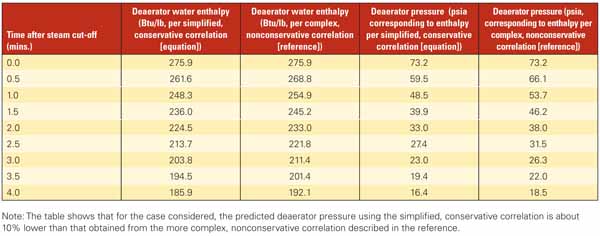
2. Good correlation with theory. The proposed simplified calculations to determine NPSH in the deaerator system give a close, conservative estimate of the more analytic approach described in the reference. Source: Bechtel Power
Options for Adding NPSH to the System
The main BFW pumps are generally large, high-energy pumps needing large amounts of NPSHr. One solution would be to raise the DA to a higher elevation to increase the NPSHa. This solution is normally not practical or cost-effective. Another approach is to install a low-speed, low-NPSH booster pump upstream of the BFW pump. The booster pump discharge pressure then provides the added NPSH required by the BFW pump. In addition, the same NPSH analysis must be made on the booster pump. The only difference is that in the case of the booster pump arrangement, the critical point and the critical point margin need to be evaluated at the booster pump suction as well as the BFW pump suction.
Additional Transient Condition
An additional transient condition that the system designer must consider occurs during a "hot start." In this situation, steam flash (water-steam mixture) can occur at the pump suction and cause cavitation damage to the pump internals. However, the mechanism causing steam flash is slightly different than what was discussed earlier.
On a plant trip, the DA pressure drops and the water temperature inside the DA drops. However, the pump and suction piping near the pump remain at a higher temperature due to the mass of the metal. As a result, when the pump is operated on a hot restart of the plant, steam flash and cavitation are likely to occur at the pump suction.
Example Illustrates Calculations
A solved example explaining the methodology for evaluating the effect of the DA pressure transient on the BFW pump NPSH is presented below. Note that the hot restart transient is not part of this calculation. Calculation of the residence time requires dimensional information of DA and the BFW pump suction piping.
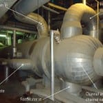
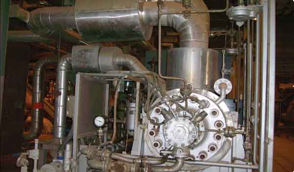
Keep your margin. Deaerator pressure decay and boiler feedwater pump net positive suction head margin during a deaerator pressure fluctuation can be calculated using the methods described in this article. Source: PGESCo., Egypt
Step 1: Collect data. Collect the following data from plant instrumentation/design documents:
-
Deaerator pressure at instant of steam cut-off, p1 = 73.2 psia
-
Saturated water enthalpy at instant of steam cut-off, h1 = 275.86 Btu/lb
-
Final deaerator pressure, p2 = 18.5 psia
-
Saturated water enthalpy at end of transient, h2 = 192.11 Btu/lb
-
Condensate flow after steam cut-off to deaerator, Wc = 29,265 lb/min
-
Warm condensate enthalpy at time of load reduction, h4 = 202.0 Btu/lb
-
Hotwell condensate enthalpy, h5 = 69.80 Btu/lb
-
Mass of water in deaerator storage tank, M = 20,3958 lb
-
Mass of warm condensate in LP heater and connecting piping, M = 32,849 lb
-
Time required to replace warm condensate, tw = M/Wc = 1.12 minutes
-
Residence time (time required to replace warm feedwater in BFW pump suction line) = 0.5 minutes (estimate based on plant-specific piping configuration)
Step 2: Perform the calculations. Use the data above with the equation provided earlier to develop the results shown in the table.
For the present case, the residence time is assumed to be 0.5 min and therefore becomes the critical point. At this point, the table shows a reduced DA pressure of 59.45 psi (or 66.1 psi, depending upon the correlation used). The actual pressure at pump suction then corresponds to DA pressure of 59.45 psi + 34 psi (where 34 psi equals the static head minus friction loss) = 93.45 psi. However, the pump suction vapor pressure during the residence time remains unchanged at 73.2 psi. This provides a margin above the pump suction vapor pressure of 93.45 – 73.2 = 20.25 psi (equivalent to 52 ft of NPSHa).
Step 3: Evaluate the results. If this calculated value of NPSHa = 52 ft is less than the NPSHr provided by the pump vendor, the pump is expected to cavitate during the transient. This means the design is inadequate and should be revised. If the NPSHa is larger than the NPSHr provided by the pump vendor, then the system should work satisfactorily during a similar pressure transient.
As a closing note, the NPSHr provided by the pump vendor is usually based on either an assumed 3% head loss or 1% head loss. It is more conservative to have the vendor provide the NPSHr based on 1% head loss.
— Contributed by S. Zaheer Akhtar, PE (szakhtar@bechtel.com), assistant chief – mechanical on assignment from Bechtel Power to Power Generation Engineering and Services Co. (PGESCo) in Cairo, Egypt. Magdy Mahmoud is manager of engineering for PGESCo., Egypt.