A supercritical plant uses a steam generator design that operates at full load above critical pressure 22.1 MPa (3,208 psia). The Benson boiler refers to a steam generator design that is capable of operating on a variable pressure ramp and is capable of startup from zero pressure at initial firing and up to supercritical pressure at higher load.
The initial versions of once-through supercritical steam generators were and still are controlled to maintain constant throttle pressure. Unit load demand is set to demand firing rate and feedwater flow. Steam temperature is controlled by the adjustment of the ratio of firing rate to feedwater flow. The furnace enclosure is maintained at supercritical pressure to avoid subcritical two-phase flow and the high temperature excursions that occur with dryout or departure from nucleate boiling (DNB) where tube failures can occur from high metal temperatures due to the inadequate steam film heat transfer coefficient. The inside tube wall temperature is suddenly higher when the water film dries out so that the steam cooling mass flux is too low for the local upset/unbalance heat flux.
Unique Benson Boiler Features
The Benson boiler is controlled employing a different design approach with furnace circuitry that, with correct operating conditions and variable pressure mode operation, will be capable of permitting appropriately located dryout to occur. Control of the A-USC Benson steam generator transitions from the minimum circulation flow recirculating mode for initial firing using the boiler circulation pump to the once-through mode where all the water entering the economizer leaves from the superheater outlet. Two-phase flow is accommodated until the critical point is reached at about 55% load where the transition to entirely single-phase flow occurs at critical pressure. Controls and design of equipment of an A-USC plant must achieve cold startup, warm restarts, hot restarts, load cycling, and shutdown.
The design is set at the Benson point, or the load at which the vertical steam separator runs dry because the fluid entering is converted completely to steam. At the Benson point the boiler circulation pump is shut off and the boiler feed pump is controlled so the feedwater flow will meet the demanded furnace enthalpy pickup function (from the economizer outlet to the primary superheater inlet) in once-through operation. By this method, the relative proportion of steam generator surface serving as evaporator and as superheater is controlled as a function of load and is stabilized. Final steam temperature control range meets a set point from about 50% to 100% load. Reheat steam temperature control range meets a set point from about 60% to 100% load.
Steam temperature is controlled by multiple stages of spray attemperation and the temperature difference across the first stage attemperators is used to trim the relationship between spray and feedwater flow in the furnace. The steam temperature control for faster transients must account for the time delay of the water entering the economizer to leave the superheater outlet, which takes about 15 minutes at minimum circulation flow load and about 3 minutes at maximum continuous rating (MCR) load. If the traditional approach of using outlet steam temperature of a variable pressure steam generator to control the feedwater-to-firing rate ratio is used, the tube metals will suffer damage due to the error in required feedwater flow caused by transit time delay.
Heating surfaces that function as preheating, evaporator, or steam generating, superheater, and reheater are shown as process lines in Figure 1, an h-p, enthalpy versus pressure diagram. The line originating at the critical point, 22.1 MPa and running out to about 2,455 kJ/kg (1,055 Btu/lb) enthalpy at 41.4 MPa (6,000 psi) is the pseudo film boiling line where the fluid below the line acts like water and above the line acts like steam. The A-USC steam generator is primarily in the greater proportion through the upper load range, a superheater. Also it should be noted for the traditional two-pass design case displayed on Figure 1, operating with variable pressure, the outlet steam temperatures of the components run nearly parallel to the isotherms so the metal temperature change in the upper load range has a very desirable minimal change.
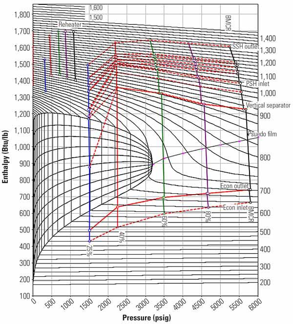
1. Enthalpy vs. pressure process diagram for an A-USC plant. Source: B&W
Variable pressure operation sets the turbine valves 100% wide open (VWO) providing better heat rate at partial load and primarily reducing the thermal stress damage to the very high temperature turbine and boiler pressure parts. The boiler can operate with zero pressure on startup due to the waterwall design and pumping a minimum circulation flow rate. There are no valves between the economizer inlet and the superheater outlet. Modified sliding pressure operation is another mode that uses throttle valve reserve so the valves are slightly closed at 90% to 95% load and stored energy of the boiler can respond more quickly to rapid load change near full load. Temperature loss due to throttling is mild and not a very severe problem for cycling damage.
Alternative Boiler Configurations
One of the design study arrangements for A-USC is the traditional two-pass configuration. Spiral-wound furnace circuitry is normally utilized in the lower furnace of a Benson boiler to accommodate variable pressure. Smooth or ribbed tubes may be used in a spiral furnace enclosure. Fewer and slightly larger tubes are used, increasing the mass flux and routing the tubes around the furnace periphery to pass through the varying heat flux zones providing more even fluid outlet temperatures. Near the elevation of the furnace arch, transition headers and piping are used for the conversion from spiral wound tubes to vertical smooth tubes in the upper furnace and arch. When the furnace is larger so the steam flow per meter (foot) of perimeter is increased, vertical tubes with optimized rib profile may be used alternatively.
The superheater, reheater and economizer heating surface arrangement are a combination of radiant and convective heat transfer surface. Pendant radiant platens are supported from the roof. At the rear of the boiler, the gas turns down into the horizontal convection pass area where the tube surface is stringer-, or end-supported at the enclosure walls. The longer-length banks are stringer-supported by economizer tube legs and are usually primary superheater and horizontal economizer surfaces. Double reheat cycles would have portions of the second (low-pressure) reheater in both down passes and some final outlet pendant surface.
The A-USC boiler should have the same gas-side temperature profile as a conventional supercritical unit while the steam is at higher temperature. The energy absorption from the boiler inlet to outlet is lower and the amount of steam flow to be heated is lower for the same power output as compared to a lower efficiency steam cycle. The higher efficiency reduces the fuel input and the combustion products’ gas weight flow, which also means the size of equipment from pulverizers, furnace, flues, air heaters, and environmental systems are smaller. The furnace size should be smaller for the same relative capacity due to lower firing rate. The convection surface tubing weight will increase due to heat transfer at a lower mean temperature difference between the hot gas and the steam.
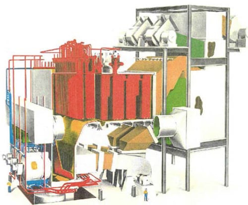
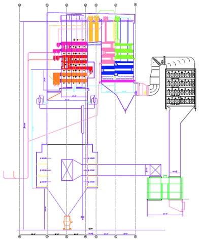
The features and arrangement selected for the A-USC steam generator are very likely to evolve from the current state-of-the-art two-pass arrangement (Figure 2).
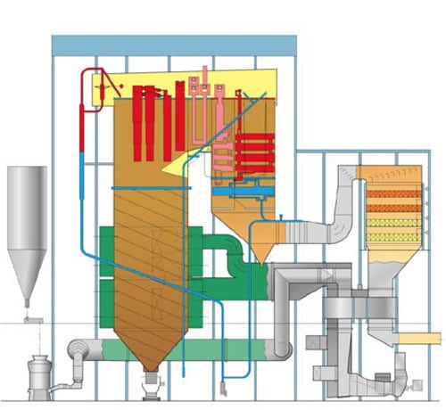
2. Current state-of-the-art 600C USC. Source: B&W
The tower design used in Europe, the ranch-style (Figure 3) and the modified tower design, which is a combination of the two-pass and tower designs, are also under consideration (Figure 4).
3. AEP Philo 6 universal pressure steam generator. Source: B&W
4. Conceptual design 800-MW modified tower A-USC. Source: B&W
The two-pass design shown in Figure 2 is considered to have the following advantages:
- Shorter steel structure than a tower design.
- Time savings of parallel construction sequence.
- Less complicated high-temperature tube sections support.
- More economical to erect.
- Less sootblowing required to clean the pendant surfaces than high-temperature horizontal surfaces in the tower design.
The tower design (Figure 3) is considered to have the following advantages:
- Better gas flow distribution resulting in lower tube metal upset temperatures.
- Wider tube spacing allowing high fuel ash removal to a single furnace hopper.
- Ability to successfully fire brown lignite.
- Drainable heating surface.
The modified tower design combines features of both designs: the structure is shorter than the tower design, and steam leads are shorter and nearer to the steam turbine. The ranch style design (Figure 3) has short steam leads, while requiring a more horizontal footprint and long ash hopper system.
Both the two-pass and tower designs have found success and enjoy preferences in select applications. Countermeasures for the negative aspects of these designs have been incorporated that keep the designs viable in the market place.
Post-combustion and oxy-combustion carbon capture and sequestration (CCS) offer opportunities along with constraints to better suit the design impact of 100C+ (200F) higher steam temperature and the new plant integration requirements. The design, when coupled with CCS oxy-combustion techniques, provides some operational advantages. The heating surface will be more effective because of the higher gas density and specific heat of the carbon dioxide. The radiant gas emissivity will be higher. The backend horizontal downpass could use a series instead of the parallel gas for reheat temperature control.
Commercial A-USC Plants
The path forward to commercial A-USC plants is to determine whether further component testing at small-scale in an electric utility setting is deemed necessary or whether the industry is ready to move forward with a small commercial-size demonstration at about 400 MW.
The customer for the product of an operating electric generating unit is the transmission grid independent system operator (ISO) that is meeting load demands at various system delivery locations by taking and transmitting power produced by many generating plants. This evolving and competitive market is served by generating units at power plants which must bid a pricing offer one day ahead and that have various operating restrictions, cost structures and characteristics that may or may not align well with the power grid’s needs at each hour of the day. Low net plant heat rate, low fuel cost, wider load turndown range, and fast rate of response are valuable characteristics that will enable the unit to achieve positive net income. The owner/designer planning a new generating unit must factor these considerations into the design.
The tendency for supercritical units has been to select a size greater than 400 MW and averaging about 750 MW. This is because economies of scale have normally resulted in the delivery of a lower cost per MW installed and a lower levelized cost of electricity. The preferred commercial-size unit has been stated to be 1,000 MW. Europe and China have been planning and constructing 1,000-MW units. The U.S. industry A-USC consortium is indicating that unit sizes between 350 MW to 1,000 MW would be possible. U.S. domestic A-USC plants will likely be teamed with CCS soon after the first commercial-size demonstration.
Design concepts for advanced ultra-supercritical steam generators are being developed, starting with the current arrangements typical of present day application, and new and significantly different steam generator arrangements are to be expected, particularly when adapted to use the advantages of oxy-combustion CCS.
The DOE and the OCDO support for the A-USC Materials Development project is greatly appreciated. The efforts of industry-wide organizations have fostered an environment of cooperation in working toward the common pre-competitive needs for ASME Code materials development for A-USC.
—Paul S. Weitzel is a technical consultant in the New Product Development, Advanced Technology Design and Development, Technology Division of Babcock & Wilcox Power Generation Group Inc.