WorleyParsons has recently been involved in various cogeneration plant studies and projects for district heating, refinery upgrades, and enhanced oil recovery (EOR) applications. In all of them, balancing thermal and power generation was central to optimizing overall plant economics.
In addition to economics, a number of significant design constraints and operational issues must be addressed if a plant is to simultaneously deal with variations in electricity and thermal demand. We have found that the key to success is to systematically evaluate the entire operating regime while assessing potential mitigating options. That is especially the case for combined-cycle cogeneration plants powered in part by midsize or large frame gas turbines.
History’s own cycle
For the purposes of this article, we define cogeneration as the simultaneous production of electrical and thermal energy from a single fuel source. The thermal energy, either in the form of steam, hot water, or another heating medium, is typically used for district or process heating and/or cooling. (In Europe, these sources of district heating are called combined heat and power plants.)
In the U.S., cogeneration has a history almost as long as standalone power generation. Most early cogen plants were built by factories that needed both power and steam. With the rise of the central station early in the 20th century, most of these factories found that they could buy electricity more cheaply from their local utility than by generating it themselves. As a result, the overall economics of independent plants that stopped or cut back on private power production suffered. That would not have been the case had utilities connected the private plants to their grids and paid for the generation. But no law forced the utilities to do that, so most didn’t, to improve their own bottom lines.
The Public Utility Regulatory Policies Act of 1978 (Purpa) addressed this economic inefficiency by requiring utilities to buy non-utility generating plants’ excess electrical output at "avoided cost" (typically, the utility’s fuel cost). Depending on its electric to thermal demand ratio, a private plant had to satisfy the minimum annual fuel use efficiency criteria to be considered a "Qualifying Facility." Purpa also created several tax incentives that motivated many thermal energy users to develop small cogeneration plants. All told, Purpa created both financial and accounting burdens for regulated utility monopolies.
Purpa began losing steam in the early 1990s when lucrative power-purchase contracts began to expire. Another nail in its coffin was the Energy Policy Act of 1992, which mandated open access to utility grids, creating a huge market for self-generators. Soon afterward, many states stopped insisting that their utilities buy power from developers of non-utility power projects. Although this represented a setback for cogeneration in the U.S., the scheme lost no momentum in other developed countries, where fuel costs more and governments continue to provide incentives to cogenerators. To complete the story, the Energy Policy Act of 2005 added five new standards to Purpa related to interconnection policies and net metering, among others (www.oe.energy.gov/purpa.htm).
System design overview
Designing a cogeneration plant requires selection of the most economic combination of equipment from among the many options available. The technology is usually chosen based on the energy forms required by the user and may include a conventional boiler, internal combustion engines, and combustion turbines. Two technical factors that play an important role in determining the plant configuration are the available fuel and the ratio of heat demand to power demand.
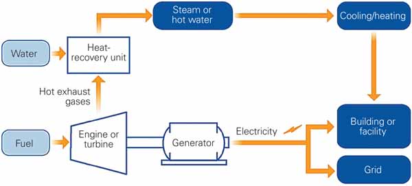
For solid fuels, the choice is typically limited to conventional boiler systems. For liquid and gaseous fuels, both internal combustion engines and gas turbines are suitable. However, the useful heat to power ratio of a gas turbine�based system is about three to four times greater than that of an internal combustion engine-based system. For this reason, gas turbines are usually specified when thermal demand is relatively high (Figure 1).
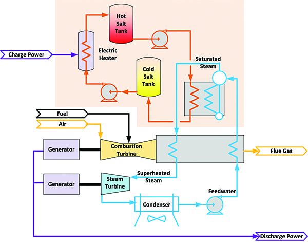
1. Why cogeneration? Combined-cycle cogeneration systems (bottom) are much more efficient than separate heat- or power-only systems. The fuel use efficiency (HHV) of separate heat and power systems is 55% to 65%, but it is 80% to 90% for a cogeneration or combined heat and power plant. Source: WorleyParsons
In a modern gas turbine–based combined-cycle power plant, about half of the fuel’s latent heat is lost in the condenser and through the stack. However, in a cogeneration plant the heat that is wasted in the condenser of a combined cycle is used effectively by the host facility, improving the plant’s thermal (or fuel use) efficiency. Depending upon the system, a cogeneration plant can be considered 80% to 90% efficient by this measure (Figure 2).
2. Energy matters. Typical heat use distribution for a combined-cycle plant powered by an F-class gas turbine. Source: WorleyParsons
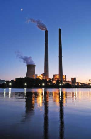
For a gas turbine�based cogeneration system, the waste heat in the turbines’ exhaust can be recovered to produce steam either for process use only (simple cogeneration) or for both bottoming-cycle power production and process use (combined-cycle cogeneration). Figure 3 is a modern, large-scale combined-cycle cogeneration facility.
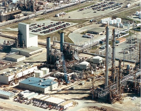
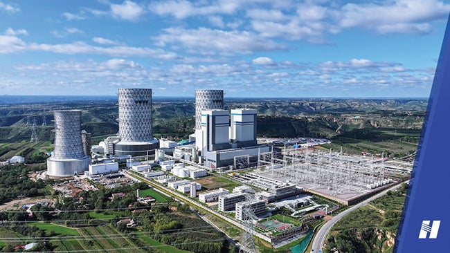
3. Pretty typical. The 450-MW Eastex Combined Cycle Cogeneration Project in Longview, Texas, has a 2×1 configuration. Its key energy converters are two GE 7FA gas turbines, two heat-recovery steam generators with supplementary firing, and one condensing/extraction steam turbine-generator. The plant sends over a million pounds per hour of high-pressure steam at two different pressure levels to an adjacent refinery. Courtesy: WorleyParsons
Operating scenarios for a combined-cycle cogeneration system vary significantly, depending on whether it is "electric primary" or "thermal primary." Also, it may be necessary to hold one form of energy production constant while the other varies. Another practical consideration is how rapidly the heat rate of the chosen simple-cycle gas turbine increases at partial load. The plant’s operating profile must be evaluated to ensure proper selection of the prime movers, safe and efficient operation of the plant, and delivery of both forms of energy.
Design challenges
WorleyParsons has designed numerous combined-cycle cogen plants of both primary varieties. Each presents its own unique design challenges.
Electric primary plants may be required to dispatch contracted power irrespective of the thermal demand. Their design becomes more challenging when the plant needs to operate at partial load to comply with the dispatch requirements while satisfying thermal demand. Operation of thermal primary plants is very different because the electricity they produce is considered a by-product. Yet their design challenges are similar to those of electric primary plants, particularly when the electricity generated cannot be economically dispatched.
It is difficult to generalize about guidelines for specifying a cogeneration system’s configuration and evaluating its performance. Nevertheless, there are a number of fundamental design issues that should be of interest to a potential developer or operator of any combined-cycle cogeneration facility. Following is a checklist of a dozen items that should be considered during the design of any system of that type:
- Calculate comprehensive heat and mass balances to determine the operating constraints at the minimum and maximum electric generation scenarios with concurrent upper and lower limits of thermal demands. For discussion purposes, the thermal demand is assumed to be steam.
- Develop the plant’s operating and dispatch profiles for both thermal and electric energy, as a way to determine system constraints.
- Select a gas turbine capable of meeting electric demand while operating at the minimum permitted load (typically, about 50%) for both electric and thermal primary plants. Remember that the design of the heat-recovery steam generator (HRSG) must accommodate supplemental firing both at baseload and partial load operation of the gas turbine if electric or steam demand is to be satisfied.
- Use supplemental firing to satisfy thermal demand if steam demand cannot be met at baseload (or minimum permitted partial load) operation of the gas turbine.
- Use fresh air augmentation to increase steam production by the HRSG if steam demand cannot be met by staying within supplemental firing limits. At many process plants and refineries, fresh air firing of small and midsize gas turbine�based plants is routinely used to maintain steam supply during gas turbine outages.
- Bring supplemental auxiliary (package) boilers on-line if steam demand still cannot be met. This is standard practice for supplying steam while the gas turbine(s) are out of service.
- Partially bypass the steam turbine, if necessary, to supply steam to the process in excess of what can be safely extracted from the steam turbine.
- Divert any additional steam to the condensing section of the turbine to generate more power if power demand increases when thermal demand is low.
- Identify process impacts due to interruption of thermal and electrical supply to determine standby equipment/processes requirements.
- Incorporate equipment/systems in the design to prevent unnecessary trips due to process transients or upset conditions. Also provide steam turbine bypass capability to supply steam to the process during periods of high demand or steam turbine outages.
- Run standby equipment in parallel for sensitive systems, as necessary, to allow smooth transitions during cogeneration system trips and upset conditions.
- Coordinate closely with the plant’s HRSG and steam turbine vendors to determine and resolve any operating constraints related to additional steam production in the HRSGs by supplemental firing or fresh air augmentation. It is important to maintain the required flow through the steam turbine without exceeding any design or operating limits.
Practical considerations
Guidelines are helpful, but case studies make the concepts and application details clear. Following are three examples from Worley Parsons project files that will get you pointed in the right direction when doing your own system evaluations. Of course, economic evaluations are based on electric rates, fuel costs, and installed plant costs, so the same analysis may result in a different set of operating profiles for your location.
Case study No. 1. A 500-MW cogeneration plant—configured 2×1 with F-class gas turbines and a two-pressure, non-reheat extraction/condensing steam turbine—supplies steam for district heating and cooling. The steam demand varies from about 100,000 lb/hr to 1,500,000 lb/hr. Two operating scenarios were evaluated in the context of this highly variable steam demand:
- Steady electric demand. In this mode, the gas turbines operate at the desired load (above the minimum permitted load). As steam demand increases, supplemental firing of the HRSGs would be implemented first. Package boilers would be brought on-line if steam demand were to exceed production using maximum supplemental firing.
- Variable electric demand. In this case, the gas turbines would be loaded to meet electric demand down to the minimum permitted load (say, 50%). Steam demand exceeding the capability of the HRSG would first be met by supplemental firing of the unit and then by bringing package boilers on-line. Note that at 50% gas turbine load, the HRSG can produce about 70% of rated steam flow without supplemental firing and nearly 100% of flow with it.
Case study No. 2. Another 500-MW cogeneration plant has the same configuration and equipment as the previous case study, but it supplies a process plant. The cogen plant was designed for partial load supplemental firing of the HRSGs. If steam demand were to exceed the level that could safely be extracted from the steam turbine, main (high-pressure) steam would be used to meet it through a pressure-reducing desuperheating station.
Case study No. 3. A 50-MW cogeneration plant with a 25-MW gas turbine, an HRSG, and a 25-MW backpressure steam turbine supplies steam to a refinery. The plant’s power demand is fairly steady. The HRSG can be fresh air�fired, operated with fresh air augmentation, or fired by supplementary fuel.
To maximize the steam production of this plant, the HRSG would first be operated with supplementary firing and then with fresh air augmentation. If a further increase in steam supply were needed, auxiliary boilers could be brought on-line. In fresh air�only firing mode, the HRSG will produce steam when the gas turbine is out of service.
—Andrew M. Donaldson is director of generation projects for WorleyParsons, a provider of professional services to the electric power industry. He can be reached at 610-855-2645 or andy.donaldson@worleyparsons.com. Kajal K. Mukherjee is an engineering technical director at the firm; he can be reached at 610-855-2632 or kajal.k.mukherjee@worleyparsons.com.