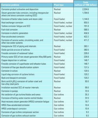
We first reported on combined-cycle plant reliability concerns due to erosive wear and flow accelerated corrosion (FAC) in heat-recovery steam generator (HRSG) pressure parts at the 1999 EPRI Maintenance Conference. More than 10 years later, these damage mechanisms remain significant contributors to forced outages, pressure part repairs, and major component replacement. The highest risk components are, with few exceptions, located within the boiler casing in modern HRSGs and, compounding the problem, are often inaccessible.
FAC damage can rapidly progress when less-than-ideal water chemistry conditions exist in conjunction with two-shift cycling operations. The damage is exacerbated by certain mechanical design configurations and choice of materials. Many combined-cycle plants have experienced detectable wall thinning of susceptible components before 25,000 hours of operation. Figures 1 through 5 are examples of the many failure modes caused by FAC in HRSGs.
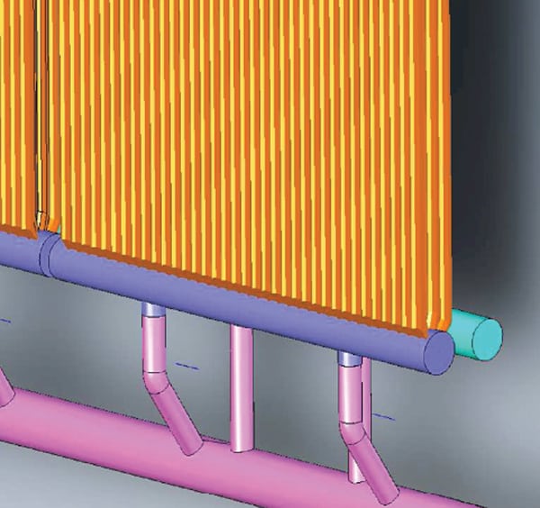 |
| 1. High local turbulence at low-pressure (LP) evaporator lower headers. At a large horizontal gas path HRSG, extensive flow-accelerated corrosion (FAC) damage was found at riser piping to the lower headers from the downcomer manifolds and at the tube-to-header weld above these risers (purple area). The plant had high duct firing capability, and steam production was very high. The damage occurred only in the leading LP evaporator panels with the highest heat input (flow rates). FAC damage was not found at the header at the lower bends, a short distance away. Source: Tetra Engineering Group |
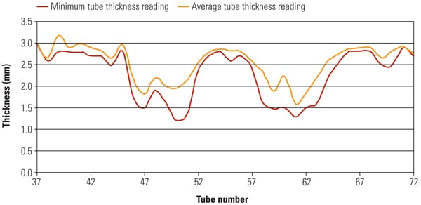 |
| 2. FAC damage found in lower LP header area. Readings of the average and minimum tube thickness were taken with nondestructive testing tools at another plant. The data show the observed wear in one-half of the LP evaporator (two modules wide). The peak wear is directly above the riser piping and decreases as you move away. Not shown in the figure is that the location of peak wear on the tube was away from the source of fluid flow. This indicated that the local turbulence was caused by the flow impacting on the side of the tube/header orifice. Source: Tetra Engineering Group |
 |
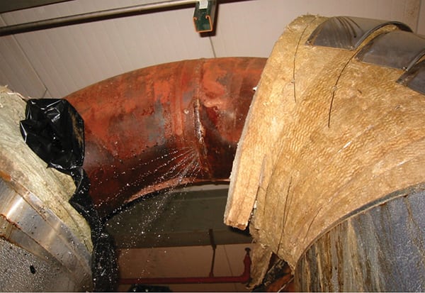
| 3. FAC damage to LP evaporator header. At this plant, a vertical gas path HRSG suffered localized FAC damage to the header and tube of the LP evaporator section. FAC damage to the header is evident. Courtesy: Tetra Engineering Group |
 |
| 4. FAC damage to tube interior. Looking inside of a header tube shows FAC damage that occurred at tube bends. Courtesy: Tetra Engineering Group |
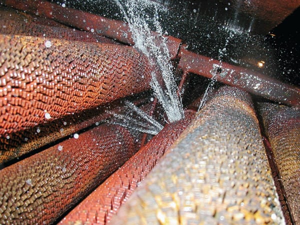 |
| 5. FAC leak in tube mid-span. Another example of isolated FAC damage is this case of a rare mid-span tube leak. The cause was found to be local turbulence originating with a poor weld joining two lengths of tube. Courtesy: Tetra Engineering Group |
Natural Gas Plants Proliferate
FAC became an issue in the U.S. in 1986 after a pipe rupture in the Surry Nuclear Power Plant resulted in six fatalities. Subsequent nuclear and conventional boiler piping failures focused industry attention on FAC and its causes. Although there were combined-cycle power plants using HRSGs at the time, they were few in number and relatively small in size. FAC did appear in these early cogeneration plants, principally because:
- Export steam required additional makeup of demineralized water and/or cleanup of returned condensate.
- Export steam water chemistry requirements impaired HRSG water chemistry.
- Favorable rates and high steam demand required high plant capacity factors.
- Many units operated under older feedwater and boiler water chemistry guidelines (pH between 8.8 and 9.2 with low dissolved oxygen) derived from mixed metallurgy system and industrial boiler guidelines.
The deregulation of the natural gas industry, beginning in the early 1990s, encouraged construction of larger combined-cycle plants. Deregulation of electricity markets and low natural gas prices spurred a “dash for gas” during the 1990s. However, rising natural gas prices and expiring long-term power purchase agreements pushed many plants into peaking or intermediate-load service. Operators of these new units also experienced FAC, but under different circumstances:
- New chemistry guidelines based on all-ferrous metallurgy.
- More resistant materials in high-risk areas of tube and pipe.
- Some units had high capacity factors, but many went to two-shift cycling when fuel prices rose and excess capacity was built in some regions.
- Export steam became less common, and plant construction shifted to refineries and other large steam users.
FAC Problems in Early Plants
Now that many early plants have more than 10 years of service, we are able to critique these HRSG designs. In these early-model HRSGs, the primary areas of FAC damage are either internal (tubes and headers) or in boiler connecting piping (evaporator risers and short feedwater piping segments). The FAC damage was often extensive, requiring major replacement and repair of pressure parts. Also, there is a large two-phase steam/water exposure in HRSG low- and intermediate-pressure components. This contrasts with conventional boiler experience, where FAC is largely confined to feedwater lines that have piping and feedwater heater components.
Many plants built in the early 1990s had extensive FAC in low-pressure (LP) evaporators and economizers. The damage to tubes, headers, and piping in HRSG evaporator panels often required complete replacement of the damaged panels or complete replacement of modules. These failures occurred within 30,000 to 60,000 operating hours (four to eight years of service). Wear rates were in the range of 1.5 to 5.5 mills/khr (0.03–0.14 mm/khr) for these components.
Subsequent failures were localized to areas of high flow, such as evaporator tubes subject to hot gas bypass or in areas of very localized geometry disturbance. As power markets evolved, many plants began or increased cycling operation or part-load operation. In some cases, reduction in the LP evaporator operating pressure produced increased two-phase flow rates and FAC wear. Changes from 0.25 mills/khr to 1.2 mills/khr were observed in one plant that correspond to water wall panel design life of 20-plus years to only a few years of service remaining. Modifying the water chemistry with tightened control can help in these situations, as can control of plant thermal conditions.
The response to these experiences was to implement better water chemistry practice both in program design and in operational control. These had the benefits of reducing the overall wear rates in high-risk zones to the 0.1 to 0.5 mills/khr range. The improved wear rates allowed newer plants to drop modified designs with higher alloy material in high-risk areas such as LP evaporator risers.
FAC Problems in Later Plants
The larger HRSGs built since 2000 have generally had less-extensive and less-rapid FAC damage than earlier plants. This reflects better water chemistry programs and control. Lower running time for many plants (3,000 to 6,000 hr/year vs. 7,500 to 8,000 hr/year), compared to early baseload plants, also tended to reduce total FAC damage, but this was not true for all plants.
The primary damage from FAC in these later plants was due to high local flow velocities, such as local flow maldistribution due to blockage, high local heat input or transient conditions, or high bulk flow rates resulting in local areas of secondary flow FAC damage. High bulk rates can be the result of high duct firing, resulting in high steam production rates or nonoptimized flow paths.
More global FAC damage has occurred in areas such as the outlets of LP evaporator tubes when part-load or other off-design condition results in non-FAC optimal flow or water chemistry conditions. FAC damage in newer plants has typically resulted in less-extensive repairs (but still operationally significant damage) than in earlier units. Damage has occurred at lower rates (longer service) with wear rates in the 0.7 to 1.0 mills/khr (0.01 to 0.03 mm/khr) and service times in the 70,000 to 90,000 hr range.
In the period of rapid growth of large HRSGs, many projects added substantial duct firing to allow peak power production or to export commercially significant amounts of steam to refinery or other customers. In some cases, high steam export made it difficult to achieve reliable water chemistry control, increasing FAC wear. Also, at full output, in some plants water flows through the areas of the HRSG most susceptible to FAC had high velocities. This led to significant local FAC wear in some areas of high-flow/nonuniform flow patterns in the range of 0.75 to 1 mills/khr, while other areas of the HRSG showed little or no FAC wear (<0.5 mills/khr). The local flow conditions produce a large increase in wear independent of overall water chemistry and temperature. Management of this FAC wear is largely a matter of modification of local flow paths and materials.
In many of these plants FAC wear rates in other areas of the same component away from the local high flows are quite low (<0.15 mills/khr), resulting in pressure part lifetime greater than 400,000 operating hours.
Future Technology Required
FAC is shifting from a rapid wear phenomenon over large areas of affected HRSG components to a slower wear process with the risk of locally higher rates. In many cases, the higher wear rates are not detectable by wear measurements in accessible locations by relation to gross flow models. The high percentage of problems in two-phase areas of LP, and to a lesser extent intermediate-pressure (IP) evaporator systems, highlighted the need for good flow modeling of these zones and FAC predictive models for two-phase conditions. More detailed fluid modeling design, inspection, and repair tools are required to identify local high-risk locations as well as the impact of operational changes on FAC wear.
Design Technology. Another key need is the mapping of test loop and advanced flow modeling studies into an easy-to-use methodology for better predicting FAC risk in highly localized zones inside the HRSG. Drawing on existing predictive approaches, it might, for example, involve an updated or extended set of geometry factors. These would characterize common structures, such as tube-to-header interfaces in the HRSG flow path. The improved method should give reasonably good predictions of wear of both “global” and “local” FAC, using only design and process data that is readily available to plant operators.
Predictive models for FAC in HRSGs are improving, but further development in the following areas are also needed:
- Two-phase conditions. Better understanding of FAC wear rates in high void fraction flow in LP and IP evaporators is required, including the impact of material removal and transport.
- Local flow disturbances. The local FAC wear condition at the HRSG tube/header interface is now recognized as a significant problem area. Identification of bulk flow and geometric conditions that lead to high FAC wear rates in this area is important.
- Local and off-design flow conditions. Better integration of FAC models with plant simulation models to identify operating modes that increase FAC risk is required.
Inspection Technology. Past efforts at improving technology for HRSG nondestructive examination (NDE) have focused on inspection in the finned tube areas not currently accessible to many NDE techniques. A bigger problem for FAC is poor accessibility of bare tube segments at headers of horizontal gas path HRSGs. Only the outermost tube rows are typically accessible, and often only part of the tube circumference for these. Borescopy can be a useful tool, but access is usually limited or requires cutting into the header or connecting piping. Advances in digital radiography and other techniques offer prospects for improved assessment of FAC damage. New technologies for under fin thickness measurement, digital radiography, and advanced borescopy all will help characterize FAC in HRSGs.
Repair Technology. FAC damage to tubes at the tube/header joint can be a large issue if more than a few tubes are affected. Improved technology for repair welding is under development and early deployment. Design to allow better access for repair is also required.
—Contributed by Peter S. Jackson, PhD, PE (pjackson@tetraengineeringgroup.com), director, field services; David S. Moelling, PE (dave.moelling@tetra-eng.com), chief engineer; and Mark Taylor (mark.taylor@tetra-eng.com), consulting engineer, Tetra Engineering