Keeping a power plant’s surface condenser in proper working order requires paying attention to balance-of-plant systems as well. Failure to monitor and maintain cooling towers and vacuum pumps in particular can lead to performance penalties or worse.
The surface condenser at a power plant has a significant effect on power generation—specifically, the efficiency with which power is generated. Any degradation in condenser performance leads to elevated operating back pressures (BP), heat rate penalties, and—in some cases—a total plant trip.
Possible culprits for performance degradation vary greatly; however, numerous condenser performance issues are not rooted in the condenser at all.
Experience has shown efficiency losses that manifest in the condenser actually start in balance-of-plant (BOP) systems such as vacuum pumps, circulating water pumps, and cooling towers. And yet, the attention these systems receive pales in comparison to the time and resources spent on condenser monitoring, inspecting, and maintenance.
The intent of this article is not to repeat the excellent work already done by the American Society of Mechanical Engineers, the Electric Power Research Institute, and the Heat Exchanger Institute with regard to monitoring, inspection, and maintenance checklists. Instead, it examines two particular BOP components that are notorious for causing condenser performance issues: cooling towers and vacuum pumps. It specifically explains why they should be included in all online monitoring and offline inspection and maintenance programs related to the condenser.
Cooling Tower Operation Effects on Condenser Operation
Most plant personnel understand in general terms that the cooling tower operation directly affects overall plant operation. The depth of this understanding varies greatly throughout the industry, and detailed knowledge of the multitude of ways a cooling tower can affect overall condenser performance is rare. It has been my experience that there are two specific areas of concern that, when left unaddressed, lead to significant losses in plant efficiency and production: proper flow distribution across cooling tower fill and recirculating cooling water flow rate.
How cooling tower efficiency directly affects a plant’s heat rate may seem a bit convoluted. For instance, for every 5-degree F rise in basin water temperature, there is a corresponding rise in condenser BP of 0.25 inches mercury (inHg); equating to a heat rate efficiency loss of 0.5% or more, depending on the type of plant.
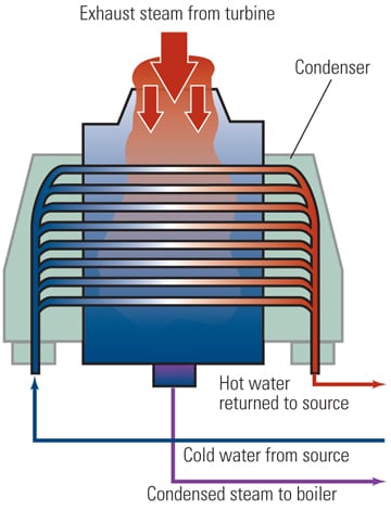
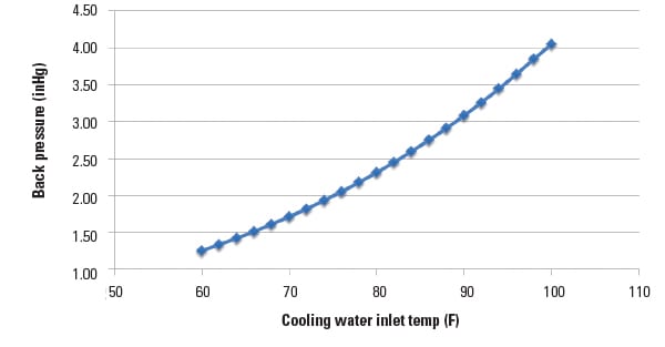
How does this 5-degree change equate to 0.25 inHg? The rise in operating steam temperature, and subsequently BP, is directly proportional to the rise in condenser inlet water temperature, with the steam tables showing an increase of approximately 0.25 inHg for every 5-degree F increase in steam temperature. So it stands to reason that degradation in cooling tower performance, resulting in a higher basin water temperature, manifests as an elevated condenser BP (Figure 1). This in turn means lower turbine efficiencies, hence the cooling tower’s direct effect on overall plant heat rate.
 |
|
1. Temperature rising. This chart shows the effect of inlet water temperature on operating back pressure. Note that it assumes a 20-degree F temperature rise and a 6-degree F terminal temperature difference. Source: Kevin Boudreaux, Nalco Co. |
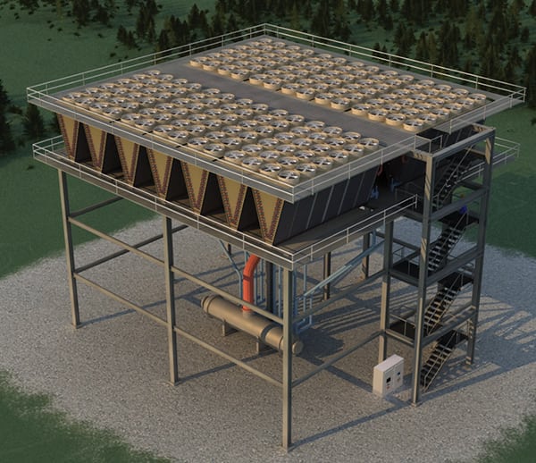
The process of evaporation (for this discussion the process takes place over a cooling tower) is used to remove heat, picked up in the condenser, from cooling water. To optimize evaporation rates, and thus heat removal, cooling towers are designed so that the proper amount of hot condenser outlet water is sprayed across the entirety of the cooling tower fill using a lateral and nozzle system (Figure 2). Falling down the large surface area of fill, cooling water comes in contact with the proper amount of counter-flowing, high-velocity air. This, in turn, causes evaporation—heat removal via phase change—to occur. The ratio of circulating water to airflow is expressed as the liquid-to-gas ratio (L:G ratio) and is a critical design point.
 |
|
2. A nozzle and lateral system above counter-flow fill packs. Courtesy: Kevin Boudreaux, Nalco Co. |
If laterals or nozzles should become obstructed, dead zones can form. These dead zones are areas in the fill where there is little to no water, and thus no water-air contact; moreover, these are areas where scaling and biological growth propagate. Conversely, there are cases where nozzles have broken off, or otherwise do not provide the proper spray cone, which causes zones of flooding. Whether starved or flooded, the L:G ratio is adversely affected and cooling tower performance degrades, directly affecting the plant’s overall heat rate.
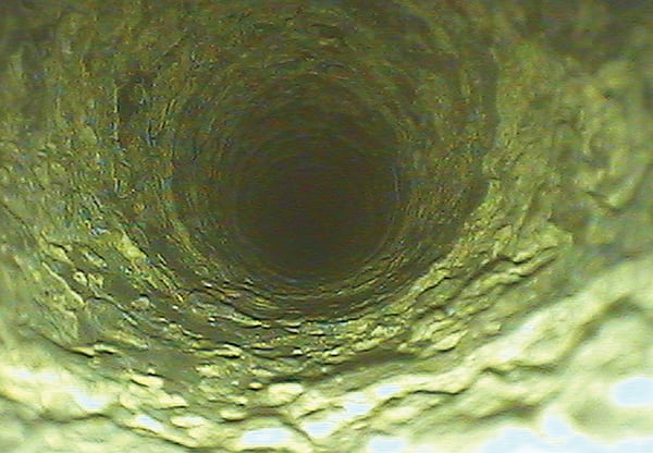
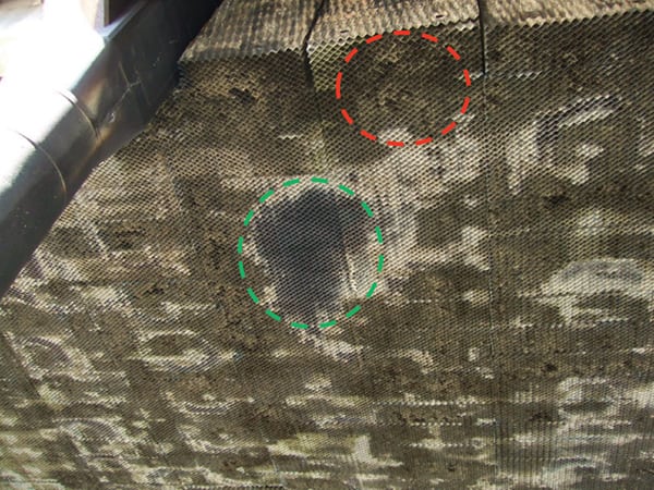
Given the cooling tower’s importance, inspecting it online to identify poor water distribution is critical and a fairly simple task (depending on the configuration, of course). By walking the perimeter of the basin and peering within the basin sections, it is easy to determine if an area is flooded or starved. Offline inspection is obviously easier, as long as the inspector knows the signs of flooded/starved sections (Figure 3).
 |
|
3. Read the signs. This photo shows both flooding (green circle) and starving (red circle) of high-efficiency fill. The nozzle above the flooded area was broken off. Courtesy: Kevin Boudreaux, Nalco Co. |
Poor flow distribution is just one example of how cooling towers affect plant operations, but it is one that is routinely seen throughout the field.
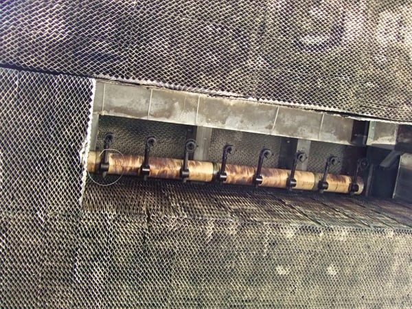
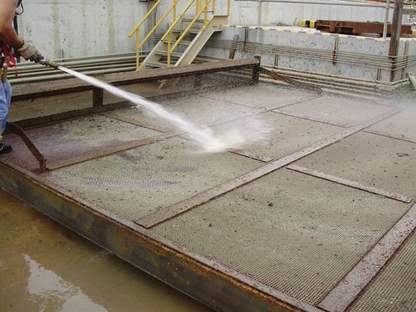
Not only can cooling tower efficiency affect condenser operation, but the ancillary components of the cooling tower, in this case recirculating water pump inlet screens (Figure 4), can also affect condenser performance.
 |
|
4. Foul. This circulating water pump’s Inlet screens are fouled with algae and solids. Courtesy: Peter Ten Eyck, Nalco Co. |
In the following example, the subject unit uses a mechanical draft cooling tower with Mississippi River water makeup. Although the makeup water is normally clarified, total suspended solids (TSS) do carry over during clarifier upsets and accumulate in the bulk water, further increasing the risk of fouling equipment such as circulating water piping, screens and filters, heat exchangers, and cooling tower fill. To complicate the issue, algae control in this particular system is very difficult, increasing the potential for TSS adherence to surfaces.
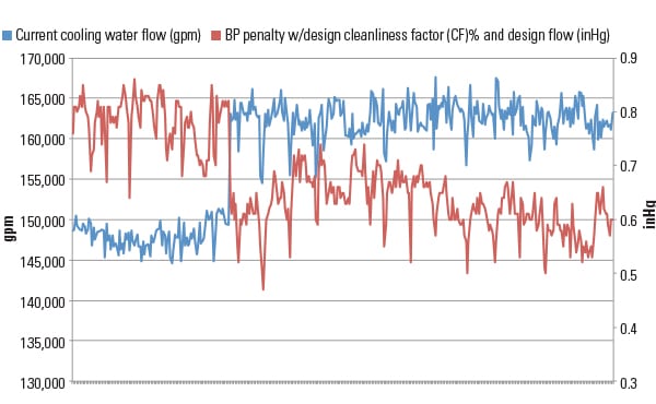
At this particular unit, the circulating water pump inlet screens were becoming obstructed with a TSS/algae agglomeration, causing a reduction in circulating water flow. That meant that each pound of water passing through the condenser would then pick up more heat than it was designed for. The result was a rise in the outlet water temperature, operating BP, and, subsequently, BP penalty (the difference between the operating and expected BP with design flow rates, Figure 5).
 |
|
5. Boogey man. These data show the effect a reduction in circulating water flow rate has on the back pressure penalty (sometimes referred to as boogey). Data are for the month of August 2014. Courtesy: Kevin Boudreaux, Nalco Co. |
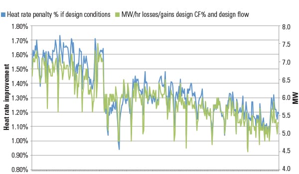
The increase in BP, 0.5 inHg in this example, means more Btus were being lost to the cooling water instead of being transferred to the steam turbine—the basis for the Carnot principle. Assuming a derate condition, the Btus lost equated to nearly 1.5 MW/hr (Figure 6), or a decrease in revenue in excess of $38,000 over a 30-day period. If considering an efficiency loss and not a derate, the degradation in heat rate was approximately 0.4% (Figure 6), or a monthly excess fuel expenditure of over $30,000. Neither a derate nor excess fuel cost is welcome, especially for something so easy to monitor and fix.
 |
|
6. One thing leads to another. These data from the month of August 2014 show the effect that a reduction in flow rate (see Figure 5, showing the same time frame) has on the heat rate and megawatt penalty. Source: Kevin Boudreaux, Nalco Co. |
It should be noted that the plant originally determined the efficiency loss to be a condenser issue, due to the increase in operating BP. However, a more detailed review of the condenser performance data uncovered the true cause: a BOP issue manifesting as a condenser performance issue.
Instrumenting a cooling tower for proper online monitoring is very difficult, and there are very few plants that have this capability. However, periodic inspection of the recirculating pump inlet screens for cleanliness and cooling tower fill for proper water distribution is simple. If, for instance, during these inspections staff find that fill flow is not distributed properly, at least the plant has a heads up for preparing and scheduling maintenance.
Vacuum Pump Operation Effects on Condenser Operation
Vacuum pumps are perhaps the most underrated piece of equipment at a power plant. Typically, unless a catastrophic failure occurs, vacuum pumps are rarely monitored, inspected, cleaned, or otherwise maintained. This is demonstrated by the fact that it would be very difficult to find a vacuum pump with the necessary instrumentation for proper online monitoring.
It is easy to understand why monitoring, inspecting, and maintaining the main condenser is critical and intuitive. Condensers are massive pieces of equipment that get a lot of press, they directly affect the steam turbine operation, and relatively speaking, the basic theory of how they work is well known. Most plant personnel understand that waterside fouling—scale, biological, and sedimentation—of the condenser tubes leads to performance degradation and overall losses in plant efficiency. This is why many condenser inspection and maintenance programs focus heavily on tubeside and water box cleanliness.
What many do not understand is that subtle changes in vacuum pump operation greatly affect condenser efficiency. This lack of knowledge leads to neglecting the vacuum pumps in condenser inspection and maintenance programs. So unless an actual event is occurring, such as water hammer or bearing failure, the vacuum pump remains hidden within the boiler and turbine deck labyrinth, unattended. And, as previously noted, these units are usually not monitored online, meaning that any performance degradation goes unnoticed. Therefore, the main focus of these systems should be online monitoring to help guide planning and scheduling of inspections and maintenance.
For instance, seal water temperature greatly influences the air removal capacity of a vacuum pump: The cooler the seal water, the higher the capacity and, conversely, capacity is reduced with warmer seal water temperatures. Seal water is cooled using a heat exchanger, which can be a shell-and-tube or plate-and-frame device, with either once-through, closed-loop, or recirculating water as the cooling medium. Upon entering the exchanger, heat contained in the seal water is transferred to the cooling medium, in turn reducing the seal water temperature. The cooler seal water is then pumped at a design flow rate (also rarely monitored) to the vacuum pump, where it provides the necessary impeller seal, allowing the pump to draw vacuum on the condenser.
If the heat exchanger becomes fouled in any way—with scaling, biological, or silting agents—heat transfer does not occur, seal water temperature remains hotter than designed, and (as previously discussed) air removal capacity diminishes. When this happens, air blanketing within the condenser occurs, the operating BP rises, and overall turbine efficiency declines. Just as with cooling tower basin water temperature, seal water temperature directly affects the overall plant heat rate.
The following example highlights how debilitating an unmaintained vacuum pump can be to condenser efficiency. Fortunately for this particular unit, vacuum pump seal water temperature is actually measured online and sent back to the plant historian. Unfortunately, it is no-action data, meaning that it is not actively monitored, and there are no setpoints/alarms around the value.
Vacuum Pump Case 1. The subject plant, located in central Florida, uses a very difficult (chemically speaking) makeup water source. It is very warm, with elevated levels of calcium, alkalinity, and phosphate, making it extremely scaling in nature. There are no cooling towers on site, and all condensers and heat exchangers, including the vacuum pump plate-and-frame exchangers, are once-through systems. Because the plant does not treat the cooling water with antiscalant, significant scaling throughout all systems has been experienced.
Due to these scaling events, taking the vacuum pump offline to clean the heat exchanger has become routine. This evolution is not prompted by the seal water temperature (even though it is in fact monitored online) but by a condenser BP high enough to nearly trip the plant. Now, undoubtedly, this is a very extreme case, but being extreme makes it one of the best illustrations of how seal water temperature directly affects actual condenser operation.
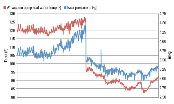
Illustrating the effect of scaling on a vacuum pump heat exchanger, Figure 7 shows the seal water temperature in this case rises to approximately 128F. With the reduction in vacuum pump capacity, the BP rises to over 4.4 inHg, initiating an exchanger cleaning. Post cleaning, the seal water temperature drops to 98F, which is much more acceptable, given that the inlet cooling water temperature was 87F. A reduction in seal water temperature by 30 degrees significantly improves the air removal capacity of the vacuum pump, thus reducing air blanketing of the condenser tubes.
More important is the decrease in BP associated with the exchanger cleaning. Figure 7 shows the BP drops from 4.4 inHg to 3.5 inHg, correlating with a reduction in heat rate of 1.0%, or 75 Btu/kWh.
 |
|
7. Drop your BP. These data from October through December 2015 show how the vacuum pump seal water temperature affects the actual operating back pressure of a surface condenser. Source: Kevin Boudreaux, Nalco Co. |
Poor control of vacuum pump cooling water chemistry is a prominent concern throughout the power industry, and it is incumbent upon generators to pay special attention to this aspect of vacuum pump operation.
Vacuum Pump Case 2. It is important to recognize that fouling of a vacuum pump heat exchanger is not limited to the waterside. In one particular case, the root cause of condenser performance degradation was ultimately identified as fouling on the shellside of a shell-and-tube heat exchanger.
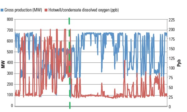
Data analysis revealed that condensate dissolved oxygen (Figure 8) and cation conductivity levels rose rapidly as the plant cycled from full load to partial load, suggesting that the cause of condenser degradation was air binding. (Air removal during low-load operation is very common and due to a change in steam pattern and a reduction in suction pressure to the vacuum pump, thus reducing its capacity.) However, performance degradation during these times is either overlooked or accepted because most plants only operate at less than full load when grid demand is low. But that does not mean it is a no-harm event. With the consensus being that poor air removal was the root cause, focus shifted to the vacuum pumps in an effort to determine if and why the system was underperforming.
 |
|
8. Dropping dissolved oxygen. Data from November and December 2015 show the effect load cycling had on condensate dissolved oxygen levels. The green line indicates the date of vacuum pump heat exchanger cleaning. Source: Kevin Boudreaux, Nalco Co. |
Instrumentation is not available on these units, so historical, online data were not available. Consequently, all troubleshooting would be done with logbooks and visual inspections, requiring isolation of the vacuum systems.
These particular vacuum pumps have a shell-and-tube heat exchanger using once-through cooling water from an on-site lake. Because the cooling water is well treated with biocide and antiscalant, waterside fouling was not suspected to be the culprit. However, further troubleshooting continued to suggest vacuum pump underperformance.
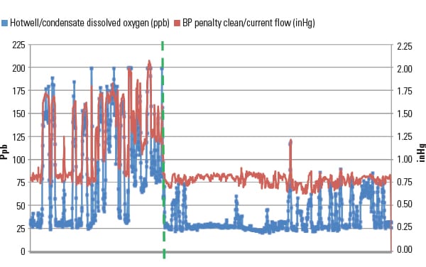
The plant decided to clean the shellside of the vacuum pump because of how easy it was to accomplish (there are two vacuum pumps in place; however, time, resources, or both caused the plant to thoroughly clean A and half-clean B). Even without a thorough cleaning on both exchangers, the data clearly show the instant improvement (Figure 9). The 4-hour cleaning translated into a BP improvement of approximately 0.5 inHg, which amounted to a 1% efficiency improvement when considering heat rate.
 |
|
9. Dramatic drop. Data from November and December 2015 show the effect the vacuum pump heat exchanger cleaning had on condensate dissolved oxygen levels and back pressure penalty. Source: Kevin Boudreaux, Nalco Co. |
Prior to the cleaning, deposit samples were not taken; therefore, it is unknown what the cleaning actually removed from the shell side. I have seen shellside bio/organic type fouling in previous cases, and though it may seem unlikely, it is important to understand that the shellside is seeing a steam/air mixture that is loaded with amine (whether ammonia or organic). As these units are brought offline, for either lead-lag operation or total plant shutdown, the condensate that forms in these exchangers sits stagnant, and very warm. With the iron and a nitrogen sources present, bio growth does not seem implausible. However, without deposit analyses, it is impossible to determine the nature of the foulant.
Perhaps even more important is the fact that after the fix, the plant is still cycling as heavily as it was before; however, improved vacuum pump capacity has led to lower dissolved oxygen concentrations in the cycle chemistry, as shown in Figure 9. Although calculating a monetary value for decreasing oxygen levels in cycle chemistry is difficult, anyone working in a power plant knows the cost of feedwater corrosion on boiler cleanings, tube failures, and forced outage time.
Air removal issues at this plant have been occurring for many years. However, because there is no online data, issues go unreported until significant plant performance deficits occur. Because plant staff now understand vacuum pumps’ complexity and relevance to plant efficiency, that equipment is now a priority, and inspection updates and cleaning protocols have been introduced.
Maintenance Well Worth the Effort
All of the case studies discussed clearly show the importance of considering the whole operation, not just the condenser, when it comes to online monitoring and offline inspection and maintenance programs. Every attempt should be made to properly monitor components that have a direct effect on the condenser operation—especially cooling towers and vacuum pumps. Not only does online monitoring identify problems before they become crippling, it also can be used in planning downtime inspections and maintenance.
Given the cost of doing nothing, whether it is a simple walk-down or a full-blown instrumentation package, time and money spent monitoring these systems is typically recovered with the identification and resolution of a single incident. ■
— Kevin Boudreaux (kjboudreaux@nalco.com) is an industry technical consultant for Nalco Co.’s Power Business Unit.