Upgrading a 1970s-era generator control system to new millennium technology in 12 days during a three-week shutdown would require careful planning and teamwork under any circumstances. The quick replacement of the governor and control system at the PT Inco smelter’s hydroelectric generation system is even more impressive because the facility is located in the middle of an Indonesian jungle.
PT Inco, an integrated mining and smelting nickel producer that is a subsidiary of Vale Inco Ltd., operates a smelter in the central part of Sulawesi, Indonesia. The facility is located literally at the end of the road and in the middle of the jungle. However, the remote site has one strong attraction: three large lakes located near the smelter’s power generation system.
The key competitive advantage that PT Inco has over other nickel producers is that it owns and operates its own hydropower stations to produce the large quantity of electric power required by the smelting process. The three nearby lakes supply water to the reservoir that is next to the power station.
Jungle Generation
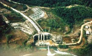
The generation system at the PT Inco smelter originally consisted of the Larona Power Station, commissioned in 1978 (Figure 1). The station was equipped with three Sulzer Francis turbines coupled to 65-MVA Hitachi generators. Due to the lay of the land, there is a 7-kilometer-long (4.2-mile-long) intake canal equipped with two radial intake control gates. The head pond at the end of the canal feeds three 1.3-km-long penstocks, which are large pipes that connect the head pond to the generators. The Larona units are equipped with bypass valves to protect the penstocks during load rejections.
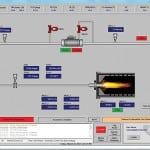
1. Larona Unit 1’s open bypass valve. As shown, the generator bypass valve will open to relieve pressure surges in the penstock in the event of a large loss of load. Courtesy: PT International Nickel Indonesia
In 1999, the Balambano Power Station was commissioned (Figure 2). It was equipped with two GE Francis turbines coupled to 80.6-MVA GE generators. In 2002, Larona Unit 3 was upgraded with a 68-MVA GE generator. The new unit has significantly higher inertia than the original unit.
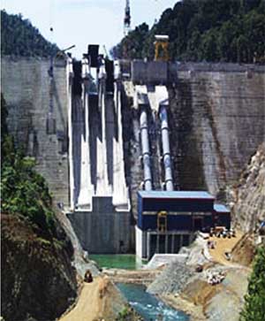
2. Balambano Power Station. The power house where the two generators are located is shown in the lower right. The two 90-m (295-ft) penstocks can be seen in the middle right portion of theimage. The three spillways in the middle left are used to allow water to bypass the generators during times of high rainfall or maintenance. Courtesy: PT International Nickel Indonesia
These five units constitute "dirty" power, whose frequency will swing between 47 and 52 hertz in what is typically a 3-minute cycle. Recent recording showed swings between 45 and 55 hertz over a two-day period, without a trip. The primary loads on this grid are four electric arc furnaces and other loads that can handle this type of power.
In contrast, "clean" power at the facility is provided by five 8-MW diesel generators, 32 1-MW diesel generators, and one 28-MW steam generator. Two DC links enable the transfer of up to 38 MW between the clean and dirty power grids.
In summary, the types of power available at the site are as follows:
-
Dirty power: 2 x 65 MW + 1 x 68 MW + 2 x 68.5 MW = 335 MW
-
Clean power: 5 x 8 MW + 32 x 1 MW + 1 x 28MW = 100 MW
-
Transferable power: 2 x 19 MW = 38 MW (as a portion of totals above)
Antiquated Controls
The Larona units used Hitachi electro-hydraulic governors and relay-based unit controls. The operating point of the generators was controlled by raising and lowering the power setting and speed-setting devices that would determine the opening position of the wicket gates. The operator performed start-up and shutdown sequencing.
The Balambano units were equipped with system automation technique (SAT) controls for unit automation and a MIPREG digital governor, which is used to measure the generator’s frequency and position the wicket gates to keep the generators’ output at 50 Hz. When the Balambano units were installed, a partial unit control system was added to the Larona units. The main function of the SAT system at Larona was to monitor equipment status.
Moving into the 21st Century
With planned increases in production, it became apparent that the control systems would have to be updated and the new unit control system would have to allow reactive power sharing. Our concern was that the additional reactive loads would push the generators closer to their maximum operating curves. Without an intelligent control system, one unit might have to provide a disproportionate share of the reactive load.
For improved water management, the system would have to be able to take directions from a higher-level control, as there would be no room for wasting water. The system would have to integrate with advanced load and generation rejection schemes in order to reduce the likelihood of grid blackouts.
Other requirements included reduced restoration time following unit trips or system blackout, enhanced monitoring and intelligent alarming to assist operators in unit restoration after equipment failures or system disturbances, and a sequence of events (SOE) recorder for improved event diagnosis.
Because our PT Inco staff is familiar with the Allen Bradley ControlLogix platform, we specified that the unit control system should be based upon that platform to minimize training requirements. Due to the plant’s isolated location, non-staff support is difficult to obtain in a timely manner; it can take a minimum of 24 hours (and usually more) to get assistance from Jakarta.
Among its multiple functions, the governor system is intended to protect the 1.3-km penstock against overpressure conditions, as a failure of the penstock would be catastrophic. The governor also must protect the canal and head pond from overtopping under blackout conditions. When the units trip, about 35,000 cubic meters of water coming down the canal have to be dealt with. A third function of the governor is the ability to bypass water from the Batubesi reservoir to the Balambano reservoir for the purposes of water management under unusual operating conditions.
Our PT Inco project team specified that the governor should be based upon a GE Woodward platform. The diesel generators use GE Woodward governors, and support is available in Jakarta and Singapore.
Searching for the Right Solutions
In early 2003, our facility assembled a team to search for the vendor that would provide a system that would suit the plant’s requirements. The team traveled to numerous sites around Asia. Most vendors were promoting their own brand of hardware and were unwilling to substitute Allen Bradley hardware.
In October 2004, our team awarded the contract to GE Singapore, which agreed to provide the Woodward governor and related mechanical components. The programmable logic controller (PLC) hardware and software were subcontracted to Rockwell Melbourne.
In August 2005, after both GE and Rockwell had finished assembling the equipment and writing the software, we jointly participated in a two-week-long factory acceptance test (FAT). Many issues had to be resolved before the equipment was delivered to the site.
Implementation Details
A 21-day shutdown was required to replace a furnace transformer. During that period, our team was allotted 12 days for construction, commissioning, and start-up. Working normal 8-hour days, our tasks would have required about 40 days, but given the allotted 12 days, we added extra crews and worked around the clock. In conjunction with the PLC replacement, other work to be done included repairing cavitation damage on the runner, repairs to the wicket gate bushings, modifying the penstock intake gate controls, and upgrades to the condition-monitoring equipment. The remainder of the shutdown was dedicated to replacing the SAT unit control PLCs on the Balambano unit. Details of some of the major implementation steps follow.
As-Built Drawings. Because the facility was commissioned more than 35 years ago, our project team needed to check the drawing package against the installation. A full-time designer was assigned to update the drawing package. This proved to be very important and helped to reduce the construction and commissioning efforts.
Detailed Engineering. We developed the mechanical, electrical, and instrumentation engineering work packages. Each discipline was split into three separate packages: pre-shutdown, shutdown, and demolition.
Factory Acceptance Test. After the PLC and governor panels were completed, they were shipped to Singapore, where they were wired together. A Woodward test set and signal generator were used to simulate the generator inputs. Our project team spent the first week of the FAT reviewing the governor operation in local mode. Various problems were encountered, and new versions of the logic were created and downloaded.
Our team spent the second week on the FAT reviewing the PLC operation. As with the governor, we encountered various problems with the logic and the human machine interface (HMI). It also became apparent that there were problems with the governor/PLC interface. Somehow, in all the preparations, this had not been included in the functional description.
Site Simulation and Training. Because we ran out of time at the FAT, when the equipment was delivered to the site in December 2005, we interconnected the governor, PLC, and HMI when they arrived. Simulation logic was developed for the PLC to mimic action of the field input and outputs. Several weeks were spent testing all of the system’s features.
We also used the simulation for training, which gave the operators an opportunity for hands-on experience. This system was a radical change from what they were used to, and as expected, they had their own list of changes and additions.
In preparation for the operator training, step-by-step procedures had been developed. These procedures were very useful during start-up, as several weeks passed between the training and actual start-up.
Different Phases of Construction
Working closely with operations and maintenance (O&M) personnel to minimize disruption to operations, the project team completed extensive pre-shutdown work that included installation of the new panels, cable trays, and cables. All cables were terminated in the new panels. New cables were prepared for termination in existing panels. The HMI hardware was installed and connected to the network. We identified the equipment that was to be demolished as well as tie-ins for the hydraulic system.
Once the shutdown began in March 2006, our project team worked relentlessly to keep to the 10-day schedule for construction, followed by 2 days of commissioning, with two crews working 12-hour shifts. Key personnel overlapped at shift change to ensure continuity and the identification of key issues that needed to be acted upon (Figure 3).
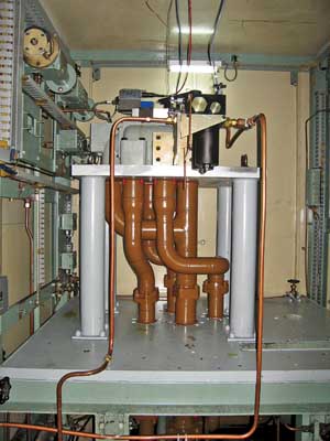
3. No more sticky wickets. The new valve manifold for the wicket gate is simple to maintain, has very few parts, and requires considerably less space than its predecessor. All linkages are electronic and totally contained within the manifold. Courtesy: PT International Nickel Indonesia
Demolition was completed in two stages: during shutdown and post-shutdown. Our team removed equipment that had required existing real estate during the shutdown. We also disconnected other pieces during the shutdown and then removed them during start-up. Several mistakes were made where, due to lack of communication, we had to reinstall items that had been demolished. A notable incident was the removal of some wiring related to the synchronizer for Units 1 and 2. We had had to hastily reconnect these wires when it was discovered that the old units could not be brought back online after they were stopped.
Commissioning the System
Our project team prepared detailed commissioning procedures for all systems (Figure 4). For the electrical and instrumentation terminations, the procedures included input/output (I/O) designation, reference drawings, testing procedures, interlock requirements, HMI indications, HMI alarms, and a sign-off. We carried out commissioning in three stages: pre-shutdown, shutdown, and start-up.
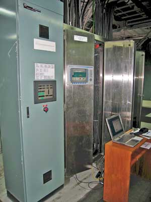
4. Keeping things udner control. The two new control panels replaced numerous panels, relays, and field devices. Courtesy:PT International Nickel Indonesia
During pre-shutdown, we brought several systems online. We verified the Ethernet communications between the PLC and the HMI. Hardwired connections and Modbus communications between the PLC and the governor were also checked. In addition, we checked Modbus communications between the PLC and the multiline generator protection relay.
Once the shutdown began, we checked the hardwired connections as they became available. In addition, discrete system checks were performed on the governor oil pumps, the generator lift pump, the cooling water systems, the wicket gate hydraulics, the bypass valve hydraulics, and the excitation system. At the time of start-up, all that was left to commission was the integration of the discrete systems that previously had been checked as stand-alone systems.
Surviving Start-Up Challenges
Start-up of the unit began with dry tests. We stroked the wicket gates and bypass valve to set the timing nuts on the distributor valves. The settings determine the maximum speed of the servo motors and were adjusted to meet the existing speeds. During this time, the vendor provided hands-on training for O&M personnel.
The next stage was to simulate the generator circuit breaker interlocks. We then began filling the penstock to begin the no-load tests. This allowed us to check the penstock intake gate interlocks. With the penstock full, our project team started the auxiliary systems manually, and we began to ramp up the generator speed. Soon after the unit started rotating, there was an unexpected sound. Workers on a previous project had installed vibration-monitoring probes but had failed to check the clearances. As a result, a series of bolts on the shaft sheared the probes and sent them airborne. Once we were satisfied that all the pieces had been found, we once again began to ramp up the generator speed, stepping uneventfully through 25%, 50%, 75%, and 100% of rated speed.
With the units up to speed, we performed the overspeed trip test. When the speed exceeded the limit, the wicket gates began to close and the bypass valve began opening. The bypass valve had been configured to open at a rate of 5% per second when the penstock pressure exceeded 16.3 bar (236 psi) and close at a rate of 2.5% per second when the pressure dropped below this limit. This caused oscillations in the bypass valve, which resulted in pressure spikes over 20.5 bar, causing one of the rupture discs to let go. We now faced the job of draining the penstock, replacing the ruptured disc, and refilling the penstock — which is typically a 12-hour process. It was decided that the governor logic had to be revised to control the bypass valve based upon wicket gate closing rate, which was how the previous governor had functioned.
We then moved on to test the canal and headpond blackout protection. We were only able to perform a simulation, because no one would give us permission to actually black out the power station.
When the unit was finally ready to be brought online, we placed the unit control PLC in automatic and started the system. The PLC brought up all the auxiliary systems while the governor brought the generator up to rated speed. We then manually synchronized the generator and held it at minimum load for 30 minutes. There were no indications of heat or vibration problems, so we gradually stepped up the load to 60 MW. Our team then took the unit offline to test the auto synchronizer. Eventually, the unit auto was synchronized. At this point the unit was handed over to operations staff and the replacement of the Balambano unit control PLCs began.
There were other start-up challenges:
-
As-built drawings. Our project team checked to ensure that all the construction and commissioning changes were recorded in the drawing package. We issued a copy of the red line drawings to the maintenance staff (a task that usually takes weeks).
-
Software fine-tuning. We had to add several changes to the governor tuning to make the unit share the load under different generator configurations. Also, we had to modify several alarm and trip setting delays to suit operating conditions.
-
Online operation. During the rough furnace operation, high imbalance currents caused the MW transducer to output less than 4 mA. This caused the governor to fail the transducer and to transfer to "speed mode." On several occasions, this caused the unit to trip. We remedied this problem by installing a digital transducer that can be limited to 4 mA.
-
Controlling water flow. In order to limit water flow through the penstock, we programmed the governor to shut the unit down if the position of the wicket gates plus the bypass valve exceeded 105%. The rough nature of the furnace load caused this problem to occur on several occasions. We added a time delay to give the governor a chance to close the bypass valve if such conditions occurred.
Meeting the Project’s Main Goals
Of the many requirements for this project, we managed to meet the important ones:
-
We returned the unit to operations in 12 days and on time.
-
The new controls have reduced unit restoration time after a trip.
-
The new HMI provides greatly advanced monitoring.
-
We provided protection against penstock overpressure.
-
We implemented canal and head pond blackout protection.
-
The controls related to bypassing water to the Balambano Reservoir are functioning well.
-
The SOE recorder is now functioning.
-
The advanced load and generation rejection schemes system has been successfully commissioned.
-
As far as achieving optimum reactive power sharing, we have the hooks in place but need new exciters before this can be realized.
- In regard to integrating water dispatch, we have the hooks in place but need to upgrade Larona 1 and Larona 2 control systems before this can be achieved.
–Kevin Geraghty (kevin.geraghty@valeinco.com) is a senior maintenance specialist with PT International Nickel Indonesia. He has 25 years of industrial experience. Starting in 2002, he worked as a control system mentor in the process plant engineering group for PT International. In 2005, he transferred to the company’s utilities engineering group.