Circulating fluid bed (CFB) dry scrubbing technologies provide distinct advantages over conventional spray dryer absorber scrubbers for removing SO2 from flue gases. The CFB also competes well against wet limestone flue gas desulfurization processes typically favored for large boilers firing high-sulfur coals. With high SO2 removal rates in a dry treatment process, the CFB scrubber appears to be the best of both technologies: a water-stingy scrubber with high SO2 removal rates.
The typical processes for removing sulfur dioxide (SO2) from coal-fired power plant flue gases include wet flue gas desulfurization (wFGD) and the more recent spray dryer absorber (SDA) technology. Both get the SO2 removal job done, although both process have a distinct advantages and disadvantages, such as producing large amounts of new waste products that require disposal or consuming large amounts of water. The circulating fluidized bed (CFB) process promises high SO2 removal efficiencies, extremely low water consumption, and the ability to bridge the size gap between the SDA and wFGD. To demonstrate why familiar options may not be the best, we begin by examining the merits of each system.
SDA Advantages and Limitations
SDA systems are typically used at plants firing low- to medium-sulfur (2%) coal. Depending on inlet SO2 loading, demonstrated SO2 removal efficiencies in the range of 90% to 95% with controlled SO2 emission rates as low as 0.065 lb SO2/million Btu are well documented with SDA systems. Removal rates in excess of 90% require the use of a fabric filter to provide additional contact time between the lime sorbent and the SO2. The filter cake on the fabric filter bags acts as a fixed bed of solids and provides an additional 1 second of contact time for enhanced mass transfer of SO2. For SDA systems, SO3removal efficiencies are typically 99%. Details of SDA technology applied to recent coal-fired projects are available online at https://www.powermag.com using the keyword “SDA.”
In the typical SDA system, the reagent slurry is pumped to the top of the SDA absorber vessel and introduced through one or more high-speed (11,000 rpm) spinning wheels within rotary atomizers located on the roof of the vessel (Figure 1). The atomizer(s) are centrally located within flue gas dispersers. As flue gas is accelerated and dispersed evenly around the perimeter of the spinning wheel, the pollutants are brought into intimate contact with a spray cloud of atomized droplets containing the sorbent. The sorbent reacts with SO2 and SO3 to form calcium sulfite and calcium sulfate while simultaneous cooling of the flue gas occurs. The flue gas then exits the absorber and is directed to a particulate collection device, either a fabric filter or electrostatic precipitator.
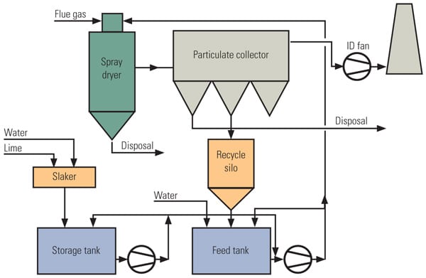 |
| 1. Typical SDA dry scrubbing system schematic. Source: Nooter/Eriksen |
SDA absorbers are downflow reactors, with the atomizers and gas dispersers located on the roof of the vessel. The absorber design is limited by two basic parameters: capacity of the rotary atomizer(s) and dispersion of the flue gas. As SDA absorbers are applied to increasingly larger gas flow rates, the energy of the gas as it is compressed and accelerated through the disperser will overwhelm and imbalance the spray cloud of atomized droplets. One SDA absorber design splits the gas flow into a roof disperser and a centrally mounted disperser to balance the spray cloud from above and below. Another absorber design incorporates three roof-mounted gas dispersers to avoid any need to balance the spray cloud.
Ultimately, the application of SDA technology is limited by the motor, gear box, and wheel capacities of the rotary atomizer. SDA systems are in operation at numerous generating plants ranging in size from 10 MW to over 600 MW. However, multiple absorber vessels have historically been required for plants greater than 300 MW. Practically speaking, SDA absorbers with a single large 1,000 hp atomizer or three 250 hp atomizers designs are limited to facilities generating approximately 350 MW. For capacities in excess of 350 MW, a second absorber vessel will result in more complex system layout and additional capital costs.
Operating labor and maintenance costs for any FGD system are functions of the system complexity and the number of rotating pieces of equipment within the envelope of the system. All systems with atomizers must be taken off-line periodically for inspection, cleaning, and parts replacement. The high-speed atomizers will develop scaling on the wheels, causing a vibration in the output shaft of the gear box or motor. Wear components, including wheel inserts, gear box bearings, and motor bearings, require monthly inspections and cleaning and periodic replacement (typically annually).
Plants will experience a reduction in SO2 removal when a single large rotating atomizer must be removed and replaced with a spare. For SDA systems with multiple atomizers, there is less SO2 removal degradation during these maintenance periods, but there will be a higher frequency of interruptions due to a greater number of machines. Also, the slakers, screens, mix tanks, agitators, pumps, piping, and valves associated with the lime preparation system represent additional maintenance items.
All dry FGD processes incorporate an aqueous phase reaction between a lime sorbent and gaseous SO2 and SO3. With FGD systems incorporating SDA technology, the lime sorbent is usually (pebble) quicklime (CaO), which must be prepared as a slurry reagent, with water added during slaking of the quicklime. The complete lime-handling and preparation system consists of truck or rail car unloading, solids-handling equipment, storage silos, detention or ball mill slakers, and slurry storage tanks. The resultant lime slurry also contains dust from the system particulate collection device to increase the total solids content of the mixture. The final ratio of solids (slaked lime plus particulate dust) to water in the slurry is always less than 1:1.
Wet Limestone Scrubbing Pros and Cons
Wet limestone FGD systems are well recognized as the predominant FGD technology for large power generators around the world. The process uses a slurry of ground limestone (CaCO3) instead of the slaked lime used in SDA processes or hydrated lime used in circulating fluid bed (CFB) systems. After truck or rail unloading of gravel limestone, the slurry is prepared using a system typically including a horizontal ball mill system that includes silos, feeders, and hydroclones in addition to the ball mills. Details of FGD technology applied to recent coal-fired projects are available online at https://www.powermag.com using the keyword “FGD.”
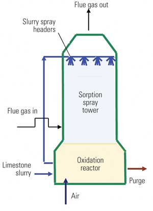
The limestone slurry is next pumped through banks of spray headers in the absorber vessel (Figure 2). Flue gas is introduced at the bottom of the absorber vessel, beneath the spray nozzles. The slurry droplets created by the spray nozzles flow countercurrent to the incoming flue gas, where intimate and uniform contact of SO2 and the calcium-rich reagent occurs.
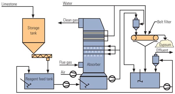 |
| 2. Typical wet FGD system schematic. Source: Nooter/Eriksen (NOTE: The flow diagrams for Figures 2 and 3 were inadvertently reversed in the print edition of this story. They have been corrected here.) |
The reactions in the absorber produce a mixture of calcium sulfite and calcium sulfate. Air, injected beneath the flue gas, promotes oxidation of sulfites to sulfates. The resulting CaSO4 by-product (gypsum) is precipitated. The oxidized slurry is recirculated to the spray headers, but a portion of the slurry is withdrawn to remove the gypsum in a separate recovery system that includes hydroclones and drum or belt filters. The recovered gypsum can then be used in commercial applications such as cement additives or wallboard.
Because of their extensive limestone preparation and gypsum recovery systems, wet FGD processes have high capital, power, and maintenance costs as compared to either SDA or CFB dry systems. The limestone raw material is a lower-cost reagent than the quicklime or hydrated lime used in the dry processes, but wet FGD processes require 30% to 40% more water, which poses a challenge in arid locations with limited water availability. Furthermore, absorber vessels for a wet system require alloy or fiber-reinforced plastic construction, whereas for dry processes unlined carbon steel is adequate. Those more-expensive materials increase costs for wet FGD systems, especially for single absorber systems.
Wet FGD is routinely used at large-scale utilities firing medium- to high-sulfur (≥3%) coals and result in SO2 removal efficiencies to 99% (depending on inlet SO2 loading) with a practical controlled rate of 0.04 lb/million Btu. To achieve SO3removal efficiencies greater than 60% using wet FGD, additional equipment (adding both cost and pressure losses) may be required if the inlet SO3level exceeds 5% of the total inlet SOx mass flow. Single wet FGD absorber sizes in excess of 1,000 MW have been installed. (Details of wet FGD systems used on many coal-fired power plants are available online at https://www.powermag.com using the keyword “wet FGD.”)
Many Advantages to Dry FGD CFB Technology
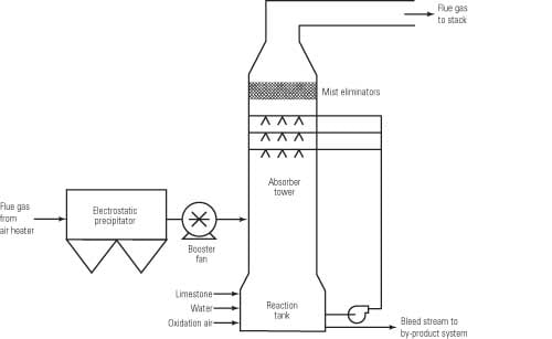
Although it is relatively new to the U.S. power industry, CFB technology has been broadly applied in Europe and China. A typical 300-MW CFB installation is illustrated in Figure 3. Today, there are more than 60 CFB scrubbers in operation in Europe, with about 34 running on coal-fired units. Seventeen of those units burning coal are rated at 300 MW or higher. Also, 14 projects totaling 6,000 MW have been built in China since 2000.
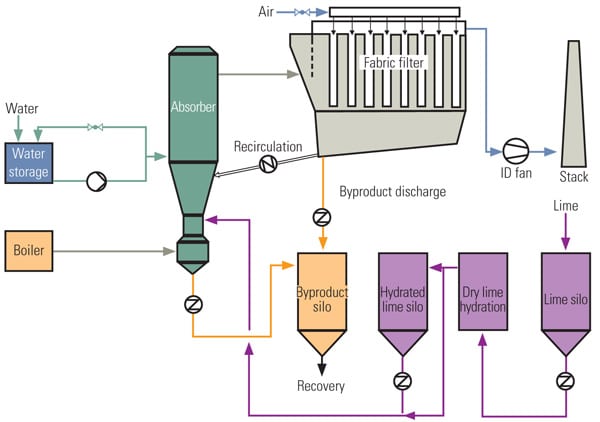 |
| 3. CFB dry scrubbing system schematic. Courtesy: Nooter/Eriksen (NOTE: The flow diagrams for Figures 2 and 3 were inadvertently reversed in the print edition of this story. They have been corrected here.) |
In North America, the largest CFB scrubber is under construction at Basin Electric Power Cooperative’s Dry Fork Station located near Gillette, Wyo. The 420-MW plant is expected to enter commercial service in 2011. A video tour of the CFB scrubber under construction is available at (case-sensitive) http://www.basinelectric.com/Projects/Dry_Fork_Station/index.html.
CFB FGD processes are substantially different than processes using SDA absorbers (Figure 4). CFB absorbers are upflow reactors, wherein all reactants (SO2, SO3, lime, and water) are introduced at the bottom of the absorber vessel along with a large portion of particulate solids collected from the downstream particulate collection device. They need no external lime preparation system requiring slakers, grit screens, pumps, and associated slurry system piping. Rather, dry hydrated lime, Ca(OH)2, is injected into the CFB absorber independently of the water and recirculated particulate.
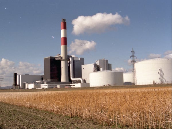 |
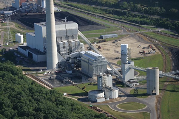
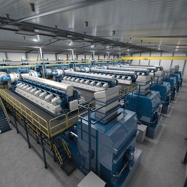
| 4. Gaining market share. A CFB dry scrubbing system is operating at the 300-MW Theiss Power Station located in Austria. There are approximately 17 CFB dry scrubber installations in Europe operating at coal-fired power plants. Source: Nooter/Eriksen |
Through multiple venturis, flue gas is introduced beneath the bed of sorbent and particulate solids and distributed across the full diameter of the CFB absorber vessel. Single-phase mechanical water injection nozzles, located on the perimeter of the absorber and above the introduction point of the recirculated and sorbent solids, spray an atomized cloud of water droplets into the bed of solids fluidized by the incoming flue gas.
CFB technology affords an enhanced heat transfer rate within the bed by spreading the water spray over a much larger surface area of solids. The ratio of solids to spray water is in the range of 20:1, translating into an approximate 20-fold increase in surface area as compared to an SDA absorber. Rather than relying on the filter cake in the downstream fabric filter for added residence time, gases entering the CFB absorber spend about 5 seconds passing through a fluidized bed some 75 feet in depth, churning within the confines of the vessel walls. The added residence time afforded by a tall, narrow CFB absorber vessel translates into improved SO2 removal efficiencies within a small FGD system footprint.
Unlike SDA absorber designs, the CFB design is not limited by the capacities of rotary atomizers. The only practical limit for a CFB absorber is its ability to disperse the flue gas throughout the vessel diameter to provide adequate suspension of the bed of solids. This limitation is readily addressed using multiple venturis for applications greater than 100 MW–150 MW.
Operating labor and maintenance costs for any FGD system are functions of the system complexity and the number of rotating pieces of equipment within the envelope of the system. Because there are no high-speed rotary atomizers or lime slurry preparation equipment in a CFB system, the annual replacement parts costs for an SDA system are at least a factor of four greater than those for a CFB dry scrubber system. In addition, CFB systems do not mandate the use of fabric filters to achieve greater than 90% SO2 removal efficiencies, as the CFB design allows using electrostatic precipitators to avoid filter bag and cage replacement costs.
CFB systems have been successfully installed at plants firing high-sulfur (up to 3.5%) coal; however, there is no technical limit on the fuel sulfur content that can be addressed using CFB technology. Demonstrated SO2 removal efficiencies are in excess of 95% and can be as high as 99% (depending on inlet SO2 loading) with controlled SO2 emission rates as low as 0.04 lb SO2/million Btu. As with SDA absorbers, SO3removal efficiencies for CFB designs can be designed for 99%, as SO3has a high affinity for the lime reagent.
Nozzles used to inject water into a CFB absorber must be removed periodically for replacement of wear components, just as with rotary atomizers used in SDA technologies. However, water nozzles are located around the entire perimeter of the CFB absorber vessel, so additional nozzle locations are typically available to allow installation of a spare nozzle prior to removing an operating nozzle for inspection or maintenance.
Bridging the Technology Gap
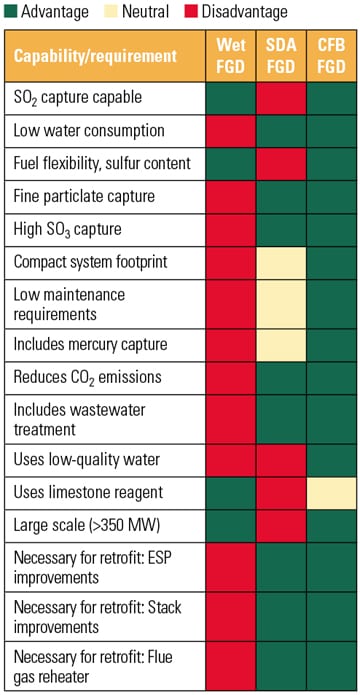
Though the choice of an SDA, CFB, or wet FGD system ultimately comes down to site-specific parameters and preferences, the application of CFB processes continues to broaden, covering the entire range of SDA processes and a larger portion of wet FGD processes (Figure 5).
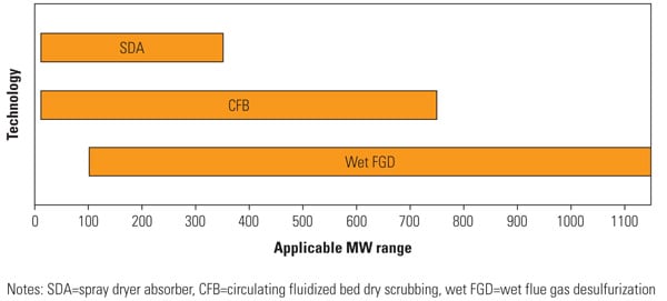 |
| 5. Comparing stats. This chart shows capacity ranges for dry and wet FGD processes compared to the CFB dry scrubber when using a single absorber vessel. The technology bridge conditions afforded by CFB technologies reflect capacity limits for single absorber vessels, capital costs, labor and maintenance costs, unit availability, and SO2 removal efficiencies. Maximum CFB single scrubber limit will vary by supplier. Source: Nooter/Eriksen |
Major considerations beyond the unit capacity and SO2 removal performance include the system footprint, system availability, particulate collection efficiency, ease of system erection, maintainability, and auxiliary power consumption. For each of these added considerations, CFB dry scrubbing can provide distinct and quantifiable advantages over competitive dry and wet FGD processes.
—Steven Moss (smoss@ ne-environmental.com) is president of Nooter/Eriksen Environmental Technologies, North American licensee of the Graf-Wulff CFB scrubber technology.