Steam turbine blade cracking often suggests the need for an upgraded blade design. Follow the process of reversing engineering a failed blade to produce a more reliable and efficient design.
Blade reverse engineering is widely recognized as a crucial step in the product design cycle. Blade surface reconstruction is an iterative process to develop mathematical models from existing physical objects for finite-element analysis (FEA), computational fluid dynamics, and rapid prototyping in order to reduce product design lead time.
In this process, precise data point measurement is important to create a valid shape. Due to the complexity of blade shape, the resultant model geometry change can lead to a large alteration in turbine performance (see sidebar). Therefore, blade shape control is critical in the design process. In essence, the blade is a complex cantilever beam, and generating an accurate simulation result makes turbine blade analysis challenging.
Finite-element analysis is the accepted tool for turbine blade structural analysis. Both the model development upgrades and analysis will be discussed.
Alstom’s Long Turbine Blade
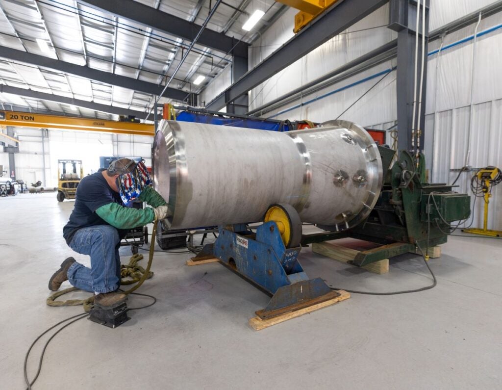
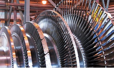
Alstom introduced its LP75 Last Stage Blade1 (LSB) last November for nuclear steam turbines. Alstom claims this 75-inch blade is the longest in the world and its exhaust area of 58 square meters is the largest of any on the market. Designed for use in the low-pressure section of Alstom’s Arabelle nuclear steam turbine, the LP75 builds on Alstom’s existing LP69 turbine blade to improve performance and achieve the best possible efficiency from nuclear steam turbines (Figure 4).
 |
| 4. Longest in the world. Alstom claims that the 75-inch-long last stage blade on its Arabelle nuclear steam turbine is the longest in the world. The Arabelle steam turbine currently powers six nuclear units and is under various stages of construction in another 18 units in four countries. Courtesy: Alstom |
The LP75 provides a reduction of one-fifth in exhaust losses compared with the existing LP69. This means that energy waste is minimized while electrical output can be maximized. Depending on project-specific conditions, an output gain of 10 MW is expected.
With this new blade, the Arabelle LSB line now offers three sizes (LP57, LP69, and LP75) and greater flexibility in plant design. Featuring the same welded rotor technology and lightweight LSB design of those earlier models, the LP75 also uses similar manufacturing processes and shares many parts, the result of a progressive product evolution.
Turbine Blade Design Fundamentals
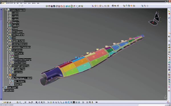
Turbine blade design involves blade solid model development, thermo-aerodynamics, and structural mechanics disciplines. The process of reverse engineering begins with determining the function of the machine part (referred to as “capturing design intent”). The accuracy of reverse engineering is limited by the applied measurement and computer-aided modeling techniques. A few of the major limitations are wear of the part; numerical, sensing, and approximation errors; and manufacturing methods. In order to ensure and enhance blade efficiency, optimizing the shape design of rotating and stationary blades is essential. The necessary steps for turbine blade reverse engineering are similar to those used in a new-product development practice (Figure 1).
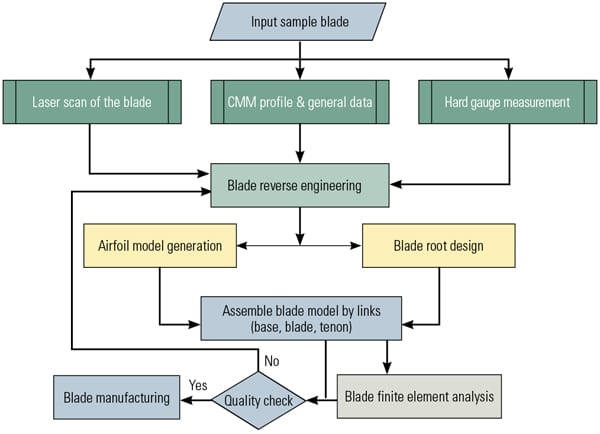 |
| 1. Process steps. Schematic of the blade model development process. Source: Alstom Thermal Services |
The process for steam turbine blade design from concept to actual product is an iterative one that includes computer-aided design (CAD) models, including blade surface for computer-aided manufacturing, FEA—and, if necessary, computational fluidized dynamics; reliability performance analysis; and design modification. The following case study presents an industrial application of an integrated reverse engineering approach to turbine blade design. The study describes a developed engineering approach to designing and upgrading a steam turbine blade from an existing part.
Data Point, Surface, and Cross-Section Generation
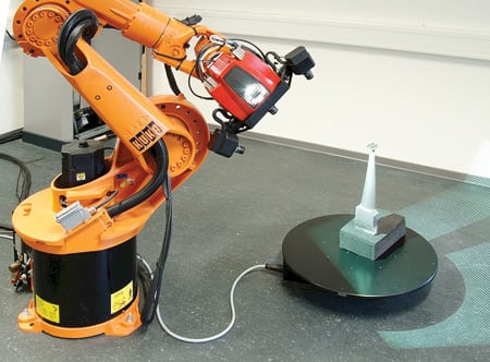
Turbine blades present challenges to manufacturers to produce and maintain the blade’s complex free-form surfaces and seemingly convoluted shapes. Contact measuring devices cannot gather enough data points to create an accurate surface profile of the airfoil’s irregular shape. Laser scanning is the best measurement method to capture the turbine blade’s entire complex features. After scanning the blade from multiple perspectives, the points of cloud data are rotated into the same reference frame and assembled into an exact 360-degree, 3-D model of the scanned part.
The data points for this case study were edited using Geomagic Studio software. Following that, the blade’s entire 3-D surface was generated in the same environment. A “perfect” CAD model is necessary for machining and FEA because turbine blades must be highly consistent in shape, weight, and geometry in order to avoid vibration and other performance-impeding characteristics. The entire CAD model can be compared with the original part to ensure the model’s quality. The inspection for this case study was performed with Geomagic Qualify engineering software. Inspection of the model and the original part indicated very good agreement (~±0.1 mm).
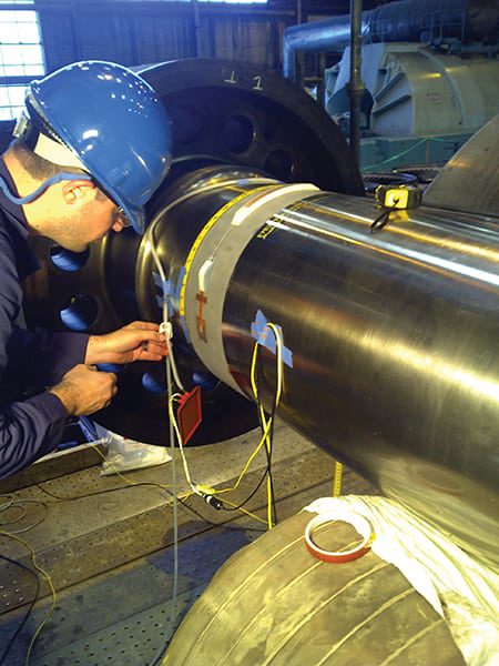
Tenon Inspection, Analysis, and Installation
Quality inspection of the turbine shaft assembly extends to the wheel steeple and the blade in order to collect information about the parts’ structural integrity and to draw a conclusion about the repair process, which can include actual repair or redesign. In this case, nondestructive testing (NDT) of the blade’s tenon revealed that a crack had initiated at the root of the tenon radius area (Figure 2).
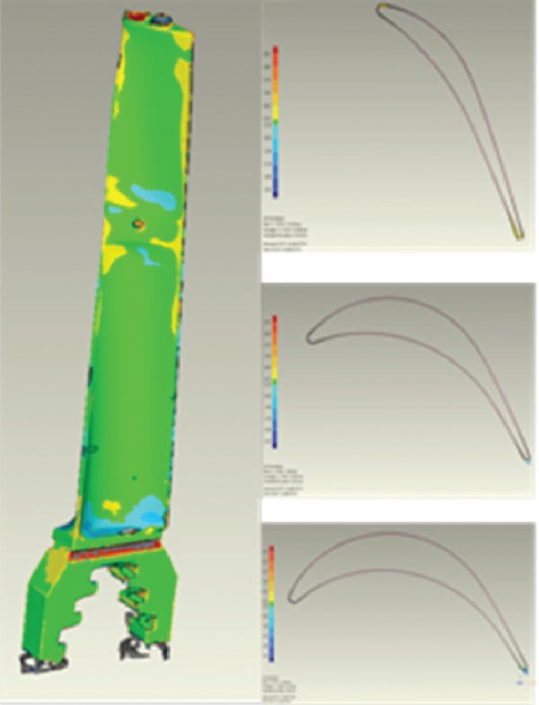 |
| 2. Tenon crack. Comparison of the original part with the developed model revealed a crack that began at the root of the tenon radius area. The areas with the highest stress are shown in red. The three figures on the right represent the blade cross-section near the root, mid-section, and tip. Source: Alstom Thermal Services |
The crack in the area of the tenon root at the base of the existing blade probably was caused by an improper size root radius, which could initiate cracking after the riveting process. The cracks appear to propagate after every cycle of the turbine operation sequence. Analysis was needed to determine the crack initiation mechanism at the root of the tenon.
A 2-D FEA indicated a distortion at the tenon root radius area after peening, as shown in Figure 3. Peening the tenon involves deliberate plastic deformation, making it easy to understand the importance of high ductility in the blade material.
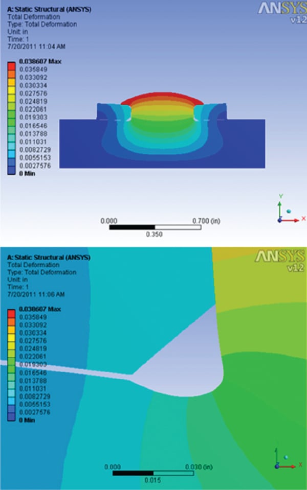 |
| 3. Distortion revealed. 2-D ANSYS model of the blade tenon after peening. The lower graphic indicates some distortion of the root radius after peening. Source: Alstom Thermal Services |
Low ductility may create serious problems during the peening process, including cracks and even fractures in the tenons. The most critical process is riveting the tenon to deform it into the classic “river” shape as part of the shroud attachment process; without this step, the tenon could not be attached. Clearly, correct assembly of the shroud band segments and riveting of the tenons are critical to long-term reliability.
The accepted refurbishment technique for blade tenon assembly is to reattach or resecure the cover band. Weld repair for blades where the crack was detected is one technique that was applied for purposes of this case study. Additional use of under-cover-band brazing further increased security of the attachment.
Shaft Steeple Inspection and Redesign
NDT of the steeple revealed that a crack initiated at the root of the steeple hook’s radius areas and appeared in every hook. In order to modify the stress field at the cracked area of the steeple hooks, a “fir tree” steeple configuration was proposed at the joint between the turbine blade and the disk. This joint represents the most critical load path within that assembly. A fir tree hook blade configuration has been commonly implemented in turbines because this design can accommodate multiple areas of contact over large contact loads. Figure 5 displays the proposed fir tree blade-steeple configuration as a possible repair solution. The new blade base design is shown in Figure 6.
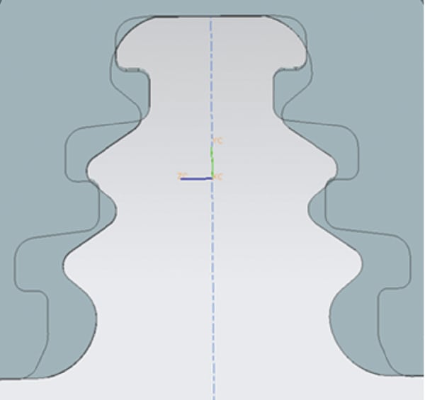 |
| 5. Proposed configuration. Schematic of the proposed fir tree configuration and of the original part comparison. Source: Alstom Thermal Services |
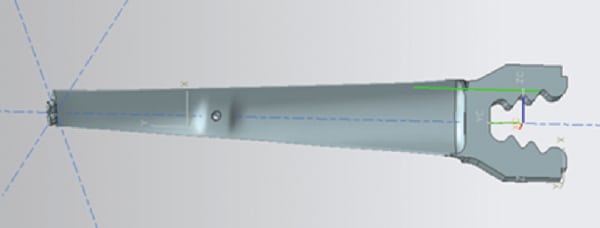 |
| 6. New blade base design. The design of the proposed fir tree base of the blade. Source: Alstom Thermal Services |
Design of the fir tree geometry was carried out using a commercially available CAD package. The model was defined parametrically in order to incorporate changes throughout the design optimization process. Every step of the modeling process was checked to make sure an adequate geometry could be produced; otherwise, a geometry failure was a signal to the optimizer to cancel or modify the model and the analysis. The blade root and the disk-steeple geometry were defined in the same way as the basic tooth, with further parameters and rules needed.
Because the fir tree steeple cross-sectional geometry is constant along the root center line, it is possible to assume that stress is present in two dimensions, although the load is actually in three dimensions. Nonetheless, it is still possible to assume that each section behaves essentially as a 2-D axial-symmetric problem with different loading applied on the hooks.
In order to verify the feasibility of the fir tree configuration, comprehensive 2-D axial-symmetric (steeple) and 3-D (blade) FEAs were executed on the original and the updated fir tree region of the blade disk assembly. Two main goals of these analyses were to create a geometric feature capable of fitting into the existing steeple domain (in other words, the part can be machined into the existing straight hook geometry) and to decrease significantly the notch stress concentration in order to increase the structure’s low cycle fatigue life.
A 2-D finite element model was developed using commercial ANSYS code, and axial-symmetric boundary conditions were applied. High mesh density was used throughout the interface region where a steep gradient in stress and strain was expected. The 2-D models were meshed with eight-node quadrilateral elements that provided a much better solution. The results of the FEA indicated that the peak stresses at the notch areas were reduced significantly using the fir tree root configuration.
With the aim of ensuring accuracy of the finite-element model solution, a 3-D blade model was developed. The turbine stage was made up of 20 pieces of seven-pack blade assemblies. To obtain an accurate finite-element model solution, it was crucial to recreate real working conditions, especially when modeling a part of a large assembly. A cyclic boundary condition was applied to the model to analyze the entire stage, and frictional contact elements were installed (with a friction factor = 0.15) between the blade-steeple interface surfaces. The model was meshed with 10-node tetrahedron elements, where the contacting surfaces and the hook radius areas were refined to increase accuracy. All models were subjected to centrifugal loading by allowing the disk and the attached blades to rotate with a specific angular velocity. In this study, the angular velocity was 3,600 revolutions per minute.
The equivalent stress distribution of the base line and the fir tree blade hooks is shown in Figures 7 and 8. The results indicate that by applying fir tree root configuration, the overall stress level is reduced significantly. It can be seen that reduction in the maximum notch stress on the order of 25% can be achieved for fir tree root design, and the low cycle fatigue life is increased proportionally.
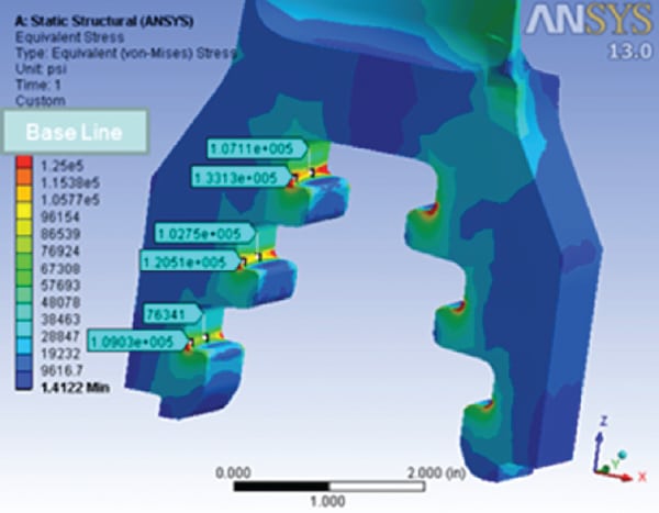 |
| 7. Reducing stress. The base line blade hooks’ equivalent stress distribution is illustrated. Areas in red represent the presence of very high stresses during operation and where the cracks occurred in the root radius. Source: Alstom Thermal Services |
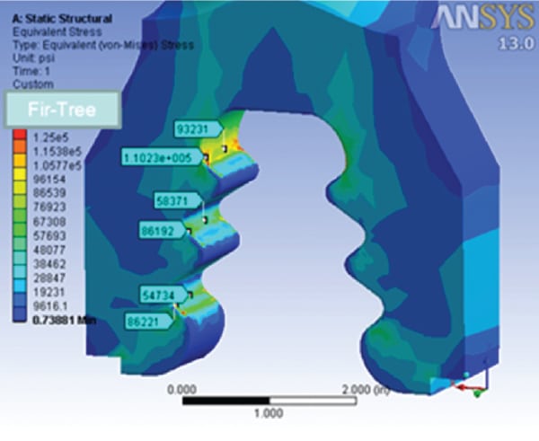 |
| 8. Improving fatigue life. The fir tree blade hooks’ equivalent stress distribution has been significantly reduced with the new attachment design. Source: Alstom Thermal Services |
In multistage turbomachinery, the interaction between the nozzles and the blades generates an excitation force on the blades, which comes from the wake of the upstream/downstream nozzles. The fundamental frequency of the excitation force due to the interaction between the nozzle and the blade is the rotor speed multiplied by the nozzle count. If the blade’s natural frequency coincides with the frequency of the excitation forces, the resultant stress may cause blade failure due to high-cycle fatigue.
Modal analysis is a powerful tool to assist in identifying and eliminating this fatigue problem. In this study, FEA was used to investigate turbine blade responses under running conditions. Finite-element modeling can be used to predict vibratory natural frequencies and mode shapes. The rotor speed at which significant forced vibration may occur is predicted with frequency speed. The natural frequency of each blade vibration mode predicted by modeling and the forcing frequencies as the function of the rotor speed can be displayed on a single graph. The intersection of the curves generated by this analysis indicated the integral order resonance points at which the possible vibratory stresses exist.
— Eugene A. Chisley, PhD, PE, and Eric Prescott are with Alstom Thermal Services.