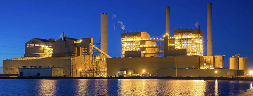
The Rovinari Power Station, located in Romania and owned by Termoelectrica, has four 330-MW coal-fired boilers that were constructed between 1976 and 1979 (Figure 1). The units fire a local lignite coal with a sulfur content that ranges between 0.5% and 1.35%.

1. The Rovinari power complex has four 330-MW subbituminous coal units in operation. Two 220-MW units have been decommissioned. The plant is being upgraded with flue gas desulfurization systems. Courtesy: Romania Business Insider
As a result of the accession of Romania into the European Union in 2007, Rovinari Power Station will soon have to meet the EU emission limit for SOx of 400 mg/Nm dry at 6% O2. A part of a EUR 1 billion modernization plan, Alstom is retrofitting wet limestone flue gas desulfurization (FGD) systems to each of the four units (Figure 2).
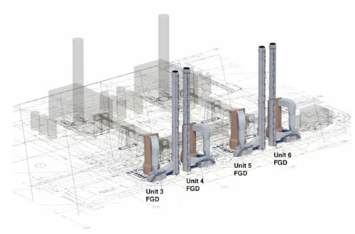
2. The planned FGD upgrades. Courtesy: Alstom
For each of the four units, the gas flow volume will be over 2,000,000 cubic meters per hour, at nominal load. Following treatment in the FGD absorber, the flue gas stream enters the FGD outlet duct at a temperature of 61C and is saturated with water. In order to minimize the droplet content of the flue gas entering the FGD outlet duct, the absorbers are equipped with two stages of mist eliminators, placed in series.
Economic Considerations for Booster Fan Location
For most FGD systems, the location of choice for the booster fans has been upstream of the FGD scrubbers, in a high-temperature nonsaturated gas stream. The obvious advantage is that the booster fans can be constructed of mild steel or a Corten type steel, keeping the cost of the booster fan itself low. However, the disadvantage is that at temperatures of 120C to 150C, the gas stream has a high volume and lower density, significantly increasing the energy consumption of the booster fans.
In recent years, the cost of energy has increased, so power plant owners are motivated to look for ways to minimize the energy consumption of the generating plant itself and thus maximize the electricity output available for delivery to the grid. At the same time, the technology of corrosion-resistant materials and of booster fan design has improved to a level where booster fans can reliably be used in the wet corrosive gas stream (Figure 3).
3. A wet booster fan must be constructed of corrosion-resistant alloys. To avoid ash or gypsum buildup on the fan blades, special spray systems and wash cycles have been developed that keep the fan blades clean during operation. This figure shows the relative location of the booster fan, scrubber, and stack. Courtesy: Alstom
Considering the need for maximum net power production and the availability of modern booster fan technology, the designers of the Rovinari FGD system found that the use of wet booster fans was highly desirable, significantly reducing the estimated power consumption per booster fan.
Effect of Booster Fan on Flue Gas Conditions
The main objective of any booster fan is to increase flue gas pressure to promote its flow through the ducts and to the top of the chimney. Due to the compression effect and fan inefficiency, a booster fan will slightly warm the flue gas as it passes through the fan before entering the stack. In the case of the Rovinari booster fans, the fan supplier has specified a temperature rise of 5.5C at nominal load and 3.0C at minimum load.
Flue gas from the Rovinari FGD system is 61C and water saturated. It will also contain up to 50 mg/Nm of fine droplets, even after passing through the mist eliminators. In a water-saturated gas flow, as seen in an FGD system without reheat, this slight warm-up of the flue gas stream could be very significant. Warming the gas will lift the flue gas temperature above its water dewpoint, potentially eliminating the constant formation of flue gas condensate in the flue gas ductwork and the wet stack. Consequently, the use of wet booster fans could be an important tool in reducing the risk of liquid carryover from wet stacks.
To evaluate the effects of flue gas temperature increase caused by the booster fans, the evaporation of the 50mg/Nm liquid load must be considered. In addition, the wet booster fans have a 2-minute wash cycle running 12 times per hour, during which water is injected at a rate of 400 liters per hour. The evaporation and flow of this washing water downstream of the fan also has to be considered.
Based on a set of thermodynamic calculations, Alden Research Laboratory concluded that, at nominal load, the temperature rise in the wet booster fans should be sufficient to:
- Evaporate the 50 mg/Nm of droplets in the gas flow.
- Evaporate the washing water from the wash cycle.
- Raise the gas flow temperature 1.95C above its water dewpoint.
During the minimum load case, assuming the same volume of water in the fan wash cycle, the heat added to the gas flow by the wet booster fans would not be sufficient to both evaporate all droplets in the flue gas and raise the temperature of the gas stream above its water dewpoint.
In addition to the findings noted above, which are based on the energy balance of the total gas stream, Alden concluded that for a portion of the droplets from the fan wash cycle, the residence time in the outlet duct would be too short for these droplets to evaporate before the chimney breeching. On the one hand, this is good, because it leaves more heat in the flue gas to warm up above its dewpoint. On the other hand, the presence of unevaporated droplets in the chimney breeching creates the need for liquid collectors and sumps in the lower zone of the breeching and lower zone of the stack. (For more information on stack drains, see "Designing Wet Duct/Stack Systems for Coal-fired Plants," POWER, March 2006.) Moreover, local, unpredictable cold points (such as expansion joints) may result in localized condensate formation, further confirming the need for a liquid collection system.
Design of the Rovinari Wet Stacks
Each of the new FGD systems at the Rovinari Power Station will be equipped with its own free-standing, 120-meter-high, 7-meter-diameter chimney. These chimneys are in accordance with the new chimney design developed by Hadek Protective Systems bv (Figure 4). Each consists of a 120-meter-high concrete shell, protected internally by a 41-mm-thick Pennguard block lining system applied directly to the concrete shell. The new chimney design does not use any internal flue, which allows it to be relatively slender and also keeps construction cost and construction time to a minimum.
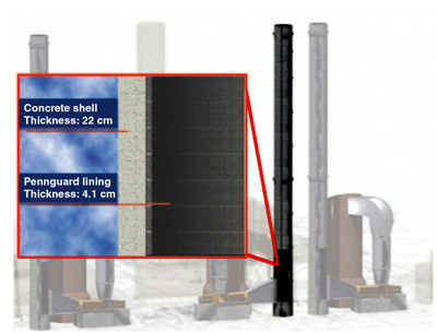
4. The Rovinari wet stacks have been designed to be well insulated so there is little heat transfer from the stack gas to the atmosphere, to minimize condensation. Source: Alstom
The Pennguard block is a closed-cell borosilicate glass block with a thermal conductivity of 0.087 W/mK at a mean temperature of 38C. As a result, Pennguard-lined chimneys are well insulated and the temperature losses of a flue gas stream flowing from the bottom to the top of these chimneys will be low. The Pennguard lining will be applied directly to the concrete shell, eliminating the need for an internal flue.
Combined Effect of Wet Booster Fans and Pennguard-Lined Chimneys
The study performed by Alden Research Laboratory shows that at an ambient temperature of -10C, the temperature of the flue gas is reduced by 1.6C as it flows from the booster fan outlet duct to the top of the chimney. This means that at nominal load the temperature increase of 1.95C created by the wet booster fans is greater than the temperature decrease experienced by the flue gas as it flows to the top of the insulated chimney. As a result, both the thermal condensation rate ("cold wall condensation") and the adiabatic condensation rate (resulting from pressure loss) are kept at zero, effectively eliminating condensation in the wet stack. It is important to consider that this finding is conservative because a portion of the fan wash water will not evaporate, effectively allowing a slightly stronger warming of the gas flow.
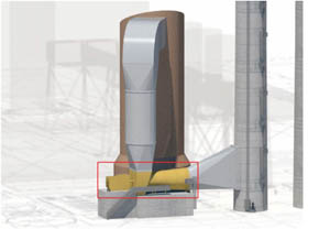
It is also important to consider that Alden Research Laboratory has developed and designed a system of liquid collectors and drains, both in the FGD outlet duct between the FGD scrubber and the wet booster fan (for liquid carryover from the FGD scrubber) and in the outlet duct and chimney breeching downstream of the wet booster fans (for nonevaporated droplets from the fan wash cycle). As usual for wet stack projects, Alden built a detailed scale model of the FGD plant, outlet duct, and chimney breeching to develop, test, and validate its proposed liquid collector and drain system (Figure 5).

5. Detailed scale model of the FGD plant. Source: Alden Research Laboratory
The study has shown that, in addition to the fan efficiency increase achieved by placing FGD booster fans downstream of the FGD scrubber, this design choice can have environmental advantages. The combination of the flue gas temperature rise in the booster fans and the excellent thermal insulation offered by Pennguard-lined chimneys can reduce or effectively eliminate condensate formation in the wet stacks. Nevertheless, the use of a well-designed system of liquid collectors and drains both in the FGD outlet ducts and in the chimney breeching is still required.
—Marco Rossi and Carlo Acquistapace are with Alstom Power Italia S.p.A. Lewis Maroti and David Anderson are with Alden Research Laboratory Inc. Albert de Kreij is with Hadek Protective Systems bv.