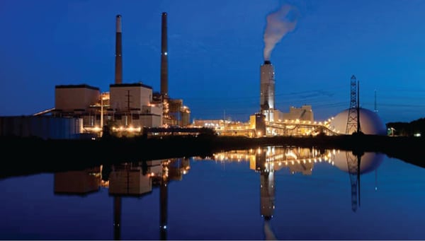
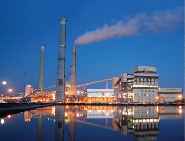
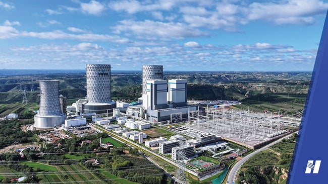
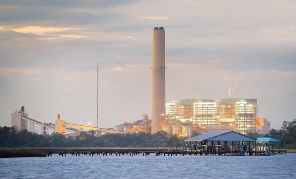
Owner/operator: St. Johns River Power Park
A recent NOx reduction project added selective catalytic reduction equipment to each of the two 640-MW, mixed coal–fired units at the St. Johns River Power Park. The selection of precisely the right catalyst required extensive long-term testing with “mini” reactors. Once the right catalyst formula was identified, the actual retrofit project was completed in a mere 23 months, an aggressive project schedule that required overcoming many design and construction challenges.
 |
| Courtesy: Black & Veatch |
St. Johns River Power Park (SJRPP) consists of two identical 640-MWnet coal-fired baseload generating units placed into service in 1987 and 1988. SJRPP is jointly owned by Jacksonville Electric Authority (JEA) and Florida Power & Light Co., which each take 50% of the plant’s generation.
The plant is fueled with coal delivered from Kentucky and West Virginia that is carried to the plant by four utility-owned unit trains. The plant enjoys a million tons of coal storage capacity, enough to keep it operating for 90 days. Coal is reclaimed and forwarded to each unit by enclosed 2,100-foot-long conveyors. Coal can also be delivered by ship or barge to the St. Johns River Coal Terminal and then forwarded to the plant by a 3.2-mile-long conveyor system at the rate of about 1,500 tons/hour, through seven transfer stations.
Both units were configured with the latest air emissions systems when constructed: A flue gas desulfurization (FGD) system removed 90% of the sulfur dioxide, and an electrostatic precipitator removed more than 97% of solid particulates from the flue gas before it was released to the atmosphere through a common 640-foot stack. Uniquely, the FGD system is configured with two operating absorption vessels and one spare vessel for increased plant reliability. Bottom ash, fly ash, and synthetic gypsum by-products from the plant’s two FGD systems are either marketed for use in construction materials or landfilled on site. Plant cooling for each unit is provided by a single 460-foot-tall natural draft cooling tower using makeup water originating in the St. Johns River.
Selecting the Catalyst
In 2006, SJRPP began preparations to upgrade the air quality control system of each unit with a selective catalytic reduction (SCR) system to reduce NOx emissions. SJRPP retained Black & Veatch to perform the engineering, procurement support, and construction management services for the SCR upgrade project. Tackticks (now a part of FuelTech Inc.) provided process consulting services to SJRPP.
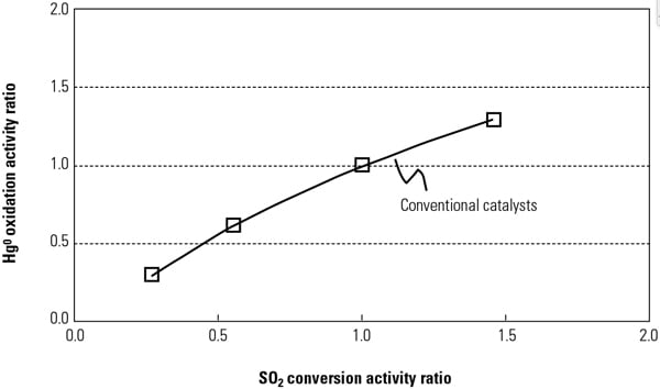
The first step was to select an SCR capable of reliable and economic operation on a variety and combination of fuels, including domestic bituminous coals, Columbian coal, and petcoke. Since 2004, combustor modifications allowed burning 100% petcoke in up to eight burners (two pulverizers) and coal in the remaining 16 burners. The high vanadium and sulfur in the petcoke, high arsenic and low calcium in the domestic coal, and high silica (up to 18% ash) in the Columbian coke made design and selection of the SCR problematic.
High arsenic levels can accelerate the rate of catalyst deactivation, and sulfur concentration determines the catalyst minimum operating temperature that is a factor in the production of visible SO3 emissions. Increased vanadium in the fuel (vanadium is also an active metal in the catalyst) will increase the production of SO3 emissions, further complicating the already complex SCR selection process. Further confusing the fuels selection, at SJRPP fuels are direct-bunkered (a specific fuel goes to a specific set of burners, as the fuels are not mixed prior to burning), meaning that no benefit could be realized for any individual fuel characteristics that might “cancel out” when blended with other fuels with different characteristics.
Given the large number of combinations of fuel mixtures possible, the only definitive approach to characterizing combinations of fuels and their interactions was to perform pilot testing. Therefore, a series of baseline or characterization tests were designed to establish actual flue gas operating conditions at various plant operating conditions.
In February 2006, Clean Air Engineering began tests to define flue gas flow and temperature distributions, emission concentrations, boiler operating conditions, and fuel and ash analyses at nine different fuel and load combinations. Other plant operating data from the plant information system were also added to the test database. The result of the test program was a definitive design basis for the SCR system; the maximum allowable percentage of petcoke in different fuel mixes that produce temperatures at the SCR less than 850F (limited bymaterial properties) is known, NOx production goals are met, and the expected concentration of SO3 produced remains low.
The next step was physical testing of catalyst offerings from three suppliers in the actual gas path to confirm predicted performance, such as catalyst activity and the mechanical design of the reactor. The suppliers provided “mini” SCR reactors that were placed in the actual flue gas path, in three separate locations for 2,100 operating hours spread over six months.
The test process ensured that each was secured in the gas pass in exactly the same orientation and each catalyst spent the same number of hours in each of the three test locations. When the test was completed, the catalysts were shipped back to the suppliers for activity and oxidation rate testing.
Based on this rigorous testing regimen, Ceram Environmental Inc. was selected as the catalyst supplier for the project. The confidence developed by Ceram during testing resulted in a performance guarantee of 85% NOx reduction and an 18,000-hour life when using 70% coal and 30% petcoke.
Unexpectedly, petcoke was later dropped from SJRPP’s future fuel plans, which meant that the design fuel would be a combination of domestic coals—a more difficult operating requirement. The concern was that the catalyst deactivation rate would greatly increase given the new mix of elements in the flue gas, thereby reducing catalyst life. Ceram repeated the in-situ testing and determined that a change in catalyst chemistry was possible without any commercial impact to the project. NOx reduction and catalyst life guarantees were maintained while burning 100% bituminous coal.
Project Challenges
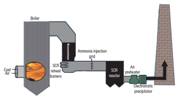
Construction of the two SCR additions was completed in just 23 months, for both units. Given the compact area of the site and poor access to the space between the boiler and stack, the SCR reactors were positioned to the east and west of each boiler-airheater center line, two 50% reactor modules per unit (Figure 1). In addition, locating SCR steel support structures directly behind each boiler, in a “traditional” SCR arrangement, would have required an additional outage for each unit (instead of the two outages that are typically seen with large complex retrofit projects). The one-outage approach also required as much pre-outage construction of ductwork and the SCR reactor as possible.
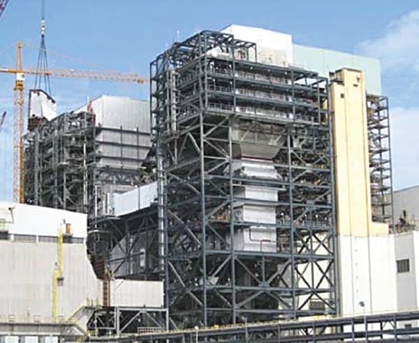 |
| 1. Double play. Two 50%-sized SCR reactor modules were placed east and west of the boiler-airheater centerline. Also included were double isolation dampers on both the inlet and outlet and large particle ash screens on the inlet of each module. Courtesy: Black & Veatch |
A further complication of using this reactor arrangement was the need for double isolation dampers on the inlet and outlet of the SCR. Coupled with the need for large particle ash (LPA) screens, this added complexity to the ductwork and SCR reactor arrangement. Existing above- and below-grade utilities in the vicinity of the SCR units (such as cooling water piping), along with the requirement to design the structures to withstand 120-mile-per-hour hurricane winds and high groundwater levels, further complicated design of the structures and foundations.
Adding an SCR also increases the pressure drop of the plant’s gas path, reducing the performance of the plant fans, especially at high loads. At SJRPP, each unit has four induced draft fans with the requirement to operate three to achieve full load. In order to keep that operating flexibility, the rotors and motors of each fan were replaced, leaving the fan housing and foundations in place. Because of the possibility of pressure drop increasing during operation (for example, plugged LPA screens), SJRPP wanted to maintain as much fan margin as possible. The forced draft and primary air fans were also modified by adding fan tips while keeping the existing motors.
A significant challenge overcome after the SCR systems entered service was the production of LPA. Under certain operating conditions, ash particles can agglomerate to form larger particles that can physically plug the catalyst. The LPA capture design process began with both computational fluid dynamics and physical flow modeling. The result was that a set of aerodynamic baffles were added to the economizer outlet to divert most of the LPA from the flue gas path into the economizer hoppers. Also, the LPA screen was coated with a special erosion-resistant material designed to withstand the erosive effects of the high-silica Columbian coals.
Commissioning of both units went smoothly. Tuning of the ammonia injection grid took less than 8 hours before the required outlet NOx and NH3 slip requirements were achieved. The LPA screen and flow baffles have also performed as designed.
— Dr. Robert Peltier, PE is POWER’s editor-in-chief.