If the U.S. regulates CO2 emissions in the future, the power generation industry is likely to be a prime target. As the table shows, electricity production accounts for nearly one-third of total U.S. carbon emissions. Capturing CO2 from coal-fired plants is of particular interest for two reasons: coal fuels about 50% of U.S. electricity production, and burning coal emits more carbon per kilowatt-hour than burning other power generation fuels. Oil-fired power plants are about two-thirds as carbon-intensive as coal-fired plants, and natural gas-fired combined-cycle plants are about half as carbon-intensive.
Sources of CO2 emissions in the U.S. in 2003. Source: DOE/EIA Annual Energy Outlook 2005
The technical challenges of CO2 capture appear to be similar in scope and complexity to those of removing sulfur dioxide (SO2) and nitrogen oxides (NOx) from flue gas—processes that many power plants now perform routinely and cost-effectively. However, the relative economic impact of capturing CO2 will be much greater, primarily because the "overhead" of CO2 capture reduces a plant’s rated capacity by 25% to 33%. Furthermore, because of the large quantity of CO2 that must be captured (about 3,000,000 lb/hr for a 1,000-MW plant), on-site storage of the captured gas is not feasible. Some means will have to be developed for transporting the captured CO2 off-site at the same rate at which it is captured.
The following paragraphs summarize the technical and economic aspects of the three currently feasible methods for minimizing or eliminating the carbon emissions of power plants.
Postcombustion capture of CO2 from flue gases (using proven chemical absorption methods) could be implemented at existing coal-fired power plants, but the impact on O&M and capital costs would be significant. Although the size and cost of the required absorber would be comparable to those of an SO2 scrubber, the absorber would consume one-quarter to one-third of the total steam produced by the plant, reducing its generating capacity by the same amount. Deploying chemical absorbers across the U.S. coal-fired fleet would require only the scaling up of units now used for applications other than power generation. An alternative postcombustion CO2 capture method might be the use of gas separation membrane technologies, which are now in the early prototyping stage.
Oxygen-fired combustion, which produces a 90% CO2 exhaust stream, provides some multipollutant control, but the technology is less mature and its O&M and capital costs would be comparable to those of postcombustion capture. Specifically, the oxygen separation plant would consume about 23% to 37% of the total plant output and cost about the same as a chemical absorber. This option is most appropriate for new plant projects and would become attractive only when new plant development becomes more desirable than retrofitting existing coal-fired plants. Significant technical challenges will have to be addressed before oxygen-fired combustion can be implemented.
Precombustion capture, which involves capturing CO2 from synthesis gas (syngas) generated by a coal gasifier, is potentially less expensive than postcombustion capture. It is considered a promising long-term option, but the required technology is still being developed. Power plants that capture CO2 precombustion also are attractive because they can be based on a combined-cycle (Brayton and Rankine) design that is inherently more efficient than the Rankine cycle employed by pulverized coal-fired plants. Another plus: Because hydrogen production would also be possible, precombustion capture would be compatible with a hydrogen economy. Precombustion capture technologies would be appropriate only for new plant projects.
Postcombustion capture
The high cost of gas compression and storage dictates that CO2 be separated from other flue gases prior to sequestration. Postcombustion capture poses two significant design challenges: the relatively low partial pressure of the carbon dioxide in the flue gas and the relatively high temperature of the flue gases.
Figure 1 is a schematic/mass-balance representation of a typical 1,000-MW coal-fired power plant whose CO2 capture equipment is installed downstream of systems for reducing emissions of NOx, particulates, and SO2. Note the supply of low-pressure steam to the "CO2 removal" box at upper right; it would not be required if the removal vehicle were gas separation membranes rather than a chemical absorber. The steam would normally be extracted from the steam cycle, decreasing the net plant output. After compression, the CO2 stream exiting bottom right of the figure would be available for sequestration.

1. Retrofit potential. Mass balance for a typical 1,000-MW (existing) power plant with postcombustion CO2 capture. Source: MPR Associates
The mass-balance numbers shown in Figure 1 illustrate the following:
- The CO2 emission rate is four times that of the coal flow.
- The concentration of CO2 may be low, but the quantities of CO2 are very large relative to other streams in the power plant.
- The CO2 concentrations are low because the air flow is an order of magnitude greater than coal flow.
Chemical absorption. Existing commercial applications of chemical absorption—the most widely used method of commercial CO2 capture for more than 60 years—include enhancing oil recovery by injecting CO2 into oil wells.
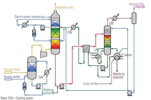
Figure 2 is a simplified schematic/flow diagram of the process. The flue gas stream enters at the left side of the figure. The chemical solvent and CO2 are exposed to each other in the absorber, where they chemically react to form a loosely bonded intermediate compound. This compound, in liquid form, is then isolated by transferring it to the regenerator (stripper), where heating causes its breakdown into separate streams of CO2 and solvent. The CO2 is then condensed and dehydrated and compressed before being stored for commercial use or sequestration.
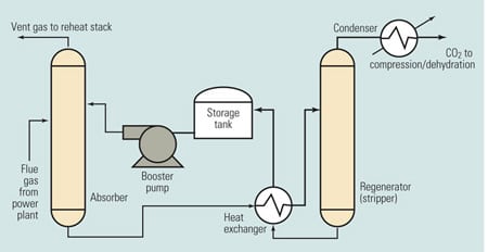
2. Can it be scaled up? Simplified chemical absorption process diagram. Source H. Herzog, "An Introduction to CO2 Separation and Capture Technologies" (MIT Energy Laboratory, 1999)
The stream of solvent—typically, monoethanolamine (MEA)—produced in the regenerator is recycled back to the absorber, enabling the process to be repeated. The storage tank in the solvent return line allows for constant CO2 removal despite variations in solvent recycling rates. The booster pump in the same line provides the pressure gradient required to transport the solvent. The heat exchanger transfers heat from the relatively hot fluid returning from the regenerator to the relatively cool fluid flowing to the regenerator.
The chemical absorption process uses pressure vessels, storage tanks, pumps, and heat exchangers similar to those of many other industrial processes. The absorber module is a gas/liquid contactor located within a carbon steel vessel or duct. This component is similar to the wet scrubber modules that have been retrofitted onto many coal-fired power plants. During operation, the absorber module pressure and temperature are approximately equal to those of the exhaust entering the module. Unlike a wet scrubber, the absorber module generates no significant waste product.
Chemical absorption has two big advantages: It produces a relatively pure carbon dioxide stream, and its technology is mature and commercially available today. However, the process has two equally big disadvantages: It imposes an "energy penalty" of 25% to 37% on power plants burning coal, and the large size of the required components not only makes the equipment expensive, but it also increases the footprint of the host plant by about 60%.
Following are some potential issues that could affect the cost of implementing chemical absorption systems:
- Existing chemical absorption equipment and processes would have to be scaled up for application to utility power generation.
- The SO2 and oxygen contained in flue gas will degrade amine solutions. An effective way to counter these mechanisms in large-scale installations that do not have effective SO2 scrubbers will have to be developed.
- Reliable operation of packed towers used in chemical absorption systems needs to be demonstrated.
In 2000 the National Energy Technology Laboratory (NETL) estimated that postcombustion capture using chemical absorption would increase the cost of electricity production by 70%. Improved sorbents may reduce the energy penalty and the capital cost of the chemical absorption process. The focus of efforts to reduce the energy penalty is on reducing the high regeneration energy requirement. It may be possible to reduce capital costs through design and technological advancements targeting the size of the absorber module and other major components. It is NETL’s goal to reduce the electricity production penalty of postcombustion CO2 capture to 20%.
Gas separation membranes. Membranes can capture CO2 by separating it from the other exhaust gases. The two most promising separation methods are solution-diffusion and molecular sieving. In the former, the gas is dissolved into the surface of the membrane and then diffused through it by mass transfer. Molecular sieving involves physically separating smaller molecules from larger ones via a very fine mesh.
Membranes are categorized by their material, of which polymeric and inorganic are the two most common types. Polymeric membranes transfer gases by the solution-diffusion mechanism. They are effective and inexpensive because their high ratio of membrane surface area to separation module volume reduces capital cost. However, polymeric membranes are susceptible to degradation and their performance is not good for certain gas flow characteristics. There appears to be a practical limit to the development of polymeric membranes for separation of CO2.
Because inorganic membranes can implement any of several separation methods, they could allow for some optimization of the process. Although inorganic membranes outperform polymeric membranes in some respects, they are much more expensive because their ratio of membrane surface area to separation module volume is much lower than that of polymeric membranes. Nonetheless, inorganic membranes are considered more promising vehicles for CO2 capture on the basis of their greater flexibility.
It may be possible to use gas separation membranes to capture CO2 from synthesis gas produced by a coal gasification process. This application is discussed in more detail in the section titled "Precombustion capture."
Overall, gas separation membranes are in an early stage of development. It has not yet been demonstrated that they can be practically applied to large-scale carbon capture.
Oxygen-fired combustion
This capture option produces a high concentration of CO2 in the exhaust gas stream by generating less non-CO2 gas during combustion. This is accomplished by burning fuel in the presence of pure oxygen rather than air. Oxygen-fired combustion is simpler and less chemically intensive than postcombustion capture, but it is less mature and similarly expensive. This option provides some multipollutant control and allows for smaller gas-handling equipment, but it imposes an energy penalty of 23% to 37% as well as higher capital cost. Pilot-scale demonstrations have been conducted and at least one full-scale project is currently under consideration.
Because oxygen is used instead of air, the nitrogen component of air and its combustion products are eliminated from the exhaust gas stream. Because nitrogen typically makes up a significant portion of the exhaust gas, eliminating it significantly increases the concentration of CO2, increasing the rate of CO2 capture without additional processing.
Because burning coal in the presence of pure oxygen raises combustion temperatures beyond the limit of furnace materials, a portion of the exhaust gas (mostly CO2) is recycled to the furnace to keep temperatures within allowable limits. For this reason, oxygen-fired combustion is sometimes referred to as CO2 recycling. In the near term, the oxygen needed would be generated on-site using mature cryogenic methods. In the longer term, a process based on ion transport membranes may prove be more attractive, but that technology is not expected to be available for at least another few years.
Figure 3 is a schematic diagram of an oxygen-fired combustion system. Particulates and sulfur compounds are first removed from the exhaust stream using standard equipment. After SO2 removal, the exhaust gas stream is approximately 90% CO2 by volume on a dry basis. After compression, this stream would be made available for sequestration. The exhaust gases are recycled back to the furnace for temperature control, as mentioned earlier. The oxygen production unit separates air into streams of oxygen and nitrogen mixed with other gases. The nitrogen and other gases are vented to atmosphere and the oxygen is sent to the furnace.
3. Seeking economic viability. A power plant using oxygen-fired combustion for CO2 capture. Source: MPR Associates
The main advantage of oxygen-fired combustion is that it is not chemically intensive. In addition, NOx normally formed from nitrogen in air is absent, and boiler size can be reduced while maintaining the same flow velocities because the volume flow rate of exhaust gas is decreased by the replacement of air with oxygen. The size of other gas-handling equipment—including equipment for removing sulfur compounds and particulates—also can be reduced.
A big disadvantage of oxygen-fired combustion is its energy penalty of 23% to 37%, primarily reflecting the need to produce pure oxygen. Another is its high capital cost, which has been estimated at about $2,040/kW. Finally, boiler corrosion problems are exacerbated by the increased concentration of SOx produced by the recycling of CO2. Sulfur is introduced in the fuel and is therefore not reduced by switching to oxygen-fired combustion. The large size of the major components significantly influences the capital cost. Adding oxygen-fired combustion to a coal-fired power plant for the purpose of CO2 capture is expected to increase the plant’s footprint by about 150%.
Oxygen-fired combustion for CO2 capture is in an early stage of technological development. Further development is needed to reduce costs. However, a true comparison of the costs of oxygen-fired combustion should take into account the reduced cost of CO2 processing and NOx reduction.
Precombustion capture
It is possible to capture CO2 in equipment installed between a coal gasifier and a combined-cycle power plant. Such a process makes available separate streams of CO2 for use or sequestration and of combustible gases (mostly hydrogen) that can be burned to produce electricity.
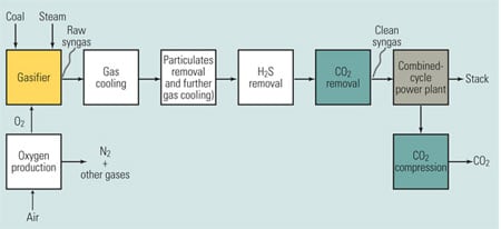
Figure 4 shows the CO2 removal equipment (and other equipment) that would need to be installed between a coal gasifier and a combined-cycle power plant to effect precombustion capture. Note the greater process complexity, relative to the other options previously discussed. The gasifier’s raw syngas output is treated by a variety of equipment on its way to becoming the clean syngas fuel for the combined-cycle plant. First, the syngas must be cooled to protect downstream equipment. Then, particulates are removed from the gas by a wet scrubbing process that also cools it further. Next, hydrogen sulfide (H2S) and CO2 are removed.

4. Too complex and costly? A power plant with precombustion CO2 capture. Source: MPR Associates
The main advantage of precombustion capture is its more moderate energy penalty of 10%, based on gasification or steam reforming. The high partial pressure of CO2 could allow for the use of a more-efficient capture technology (that is, physical absorption), further reducing the energy penalty.
The primary disadvantage of precombustion capture is that the total capital costs of the generating facility are very high. Operating costs are higher than for standard plants due to the energy penalty, but they are lower than for postcombustion capture. In 2000, the DOE estimated that the use of precombustion capture would increase the cost of electricity production by 25%. Now its goal is to reduce the production penalty to 10%, making precombustion capture even more attractive than a postcombustion capture process. However, affordable precombustion capture will require significant R&D investment. Hot gas cleanup technology and improved oxygen production processes are two promising areas of development.
Gasification options. Precombustion capture is achieved by adding additional processing steps to coal gasification or steam reforming of natural gas. Gasification is addressed here because it is the more promising application for power production in conjunction with sequestration.
Gasification partially oxidizes a solid hydrocarbon fuel to produce a gaseous fuel. The most common version of this process is coal gasification—the conversion of coal to syngas. Syngas has several uses, one of which is as a fuel for power generation. For precombustion capture, CO2 is removed prior to combustion.
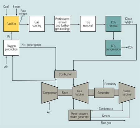
When syngas is used to fuel a plant similar to a traditional combined-cycle power plant, the process is referred to as integrated gasification combined cycle (IGCC). There are many different possible configurations for an IGCC plant, of which Figure 5 is a simplified example—as well as an expanded version of Figure 4. The inputs to the gasifier are coal, water, and oxygen. Oxygen, rather than air, is fed to the gasifier to make the CO2 partial pressures high enough to allow use of more energy-efficient CO2 removal processes. Steam is required because it is one of the reagents of the chemical reaction that take place inside the gasifier. The products of gasification are syngas (mostly hydrogen) and carbon monoxide (CO). An additional processing step not shown in Figure 5 is a shift reaction that reacts the CO with steam to produce CO2 and hydrogen.
5. The most promising option. An IGCC power plant with CO2 capture. Source: MPR Associates
Modern gas cleanup technology requires the gas to be cooled before processing. This cooling can be achieved more efficiently using heat-recovery heat exchangers that produce steam; however, this adds operational complexity. Gas cooling is typically integrated into the gasifier design. Particulate removal equipment (for example, a venturi scrubber) also can provide additional gas cooling. An alternative to extensive gas cooling is to use hot gas cleanup technology, which is still in a developmental stage.
If the syngas is at a relatively high pressure compared with exhaust gases, the more efficient process of physical absorption (which is discussed later) can be used instead of chemical absorption. Carbon dioxide is removed from the syngas after H2S is removed. A few different processes could potentially be used to remove the CO2. These options also are discussed below in greater detail. After compression, the removed CO2 is ready for sequestration.
The syngas is burned in the gas turbine combined-cycle power plant. If the gasifier is fired with oxygen and fuel nitrogen compounds are removed during gas cleanup, very little NOx is formed, and what is formed is exclusively in the combustion turbine. Waste heat contained in the turbine exhaust gas can be captured and converted to steam (for use by the plant’s steam turbine) by a conventional heat-recovery steam generator.
The compressor for the gas turbine also supplies compressed air to the oxygen production unit, which separates air into separate streams of oxygen and nitrogen combined with other gases using the method described for oxygen-fired combustion. Near-term technology options involve using cryogenic oxygen production methods, while ion separation membranes have potential for longer-term (2010) application. The oxygen is an input to the gasifier, and the nitrogen is sent to the combustion chamber to reduce NOx emissions by decreasing combustion temperatures.
CO2 capture options. Any of several processes could potentially be used to capture CO2 in this application. The options are different than those for postcombustion capture because with precombustion capture, the CO2 in the input gas stream is at a significantly higher partial pressure.
Physical absorption is a mature technology and is being used to capture CO2 today. The Great Plains Synfuels plant near Beulah, N.D., has been capturing CO2 on a large scale for 20 years using this process. It would be relatively easy to adapt the technology for precombustion CO2 capture at an IGCC power plant. As mentioned earlier, physical absorption is also the process that would be used to remove sulfur products during gas cleanup. Some economies of scale can be achieved by sharing equipment between the absorption systems for sulfur removal and CO2 removal. However, two separate gas streams are required because the sulfur products must be kept separate from the CO2 after removal. Physical absorption, which is effected by mass transfer of gas molecules into a solvent, is a complicated, capital-intensive process. The solvent used would likely be Selexol, which is currently used in industrial applications.
Other precombustion options include membranes, such as those described earlier in the section on postcombustion capture, and hydrate-based separation. Although the DOE has proposed the use of membranes in the FutureGen power plant, membranes for this application are still in the research and development phase.
Hydrate-based separation is a novel concept that aims to use CO2 hydrate—an ice-like substance that is stable at high pressures and low temperatures—to trap CO2 molecules in a lattice of water molecules. The process begins by forming the hydrate by exposing the syngas (containing CO2) to water under high pressure. As the hydrate forms, the CO2 is captured. The hydrate is then separated and disassociated, thereby releasing pure CO2. This technology—which the DOE considers the most promising long-term CO2 capture technology identified to date because its energy penalty may be as small as 6% to 8%—is currently in the R&D phase.
—Lance C. Elwell and Willard S. Grant are engineers at MPR Associates Inc. Elwell can be reached at 703-519-0440 or lelwell@mpr.com. Grant can be reached at 703-519-0224 or wgrant@mpr.com.