Coal-fired plants have been powering the electric grid for more than a hundred years, but the technology being used in them is not stagnant, as many advancements have been made. One new design—the Clean Combustion System Steam Generator—has been proven in pilot testing to increase efficiency while reducing emission control costs. It could be a game-changer for the industry.
The markets for new coal-fired steam generators will be driven by 21st century technologies that provide high-efficiency, low-pollutant emissions, and low-cost electricity. CastleLight Energy is a technology management firm that proposes a new CCS Steam Generator (CCS-SG) design incorporating the field-demonstrated Clean Combustion System (CCS). The CCS technology evolved from fundamental combustion research developed at Rockwell International for NASA’s large moon-rocket engines.
The proposed CCS-SG features a compact furnace design with a small footprint per MWth and a large MW-per-ton-of-steel steam capacity. These fundamental characteristics are found in the 1950s Babcock & Wilcox cyclone wet-bottom electric generating units (EGUs)—a low-cost steam generator design that, in its time, captured a large U.S. EGU market. As important, the CCS-SG uses equipment, steels, refractories, and instrumentation in commercial use today on coal-fired EGUs and which are very familiar to most plant operators.
Today’s Coal-Fired Electric Generating Unit
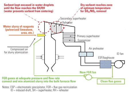
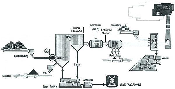
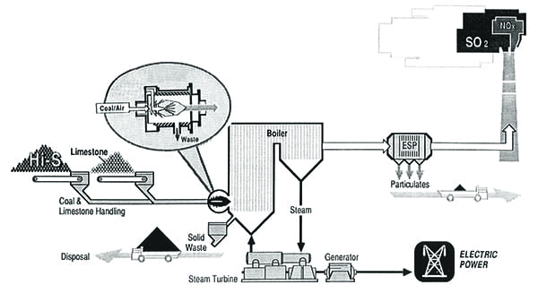
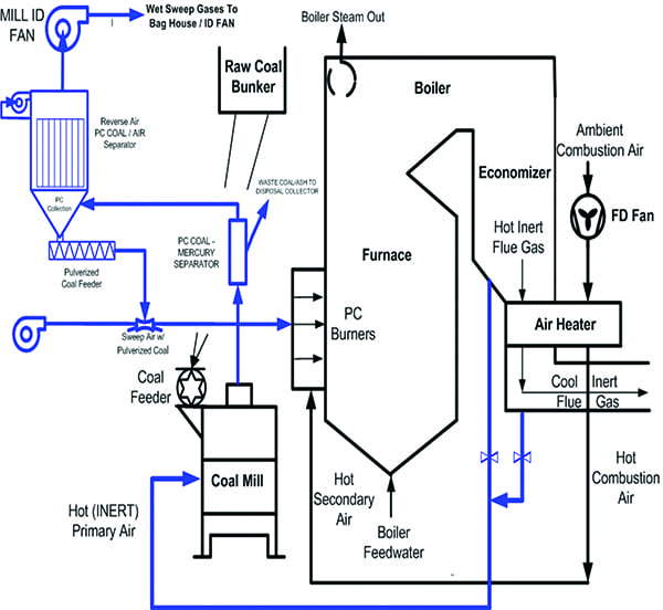
Figure 1 illustrates today’s coal-fired EGU steam generator and the back-end emissions control equipment used to meet U.S. Environmental Protection Agency (EPA) air quality regulations, such as SO3 (Trona injection), NOx (selective catalytic reduction [SCR] and ammonia), mercury (activated carbon injection), particulate (electrostatic precipitator [ESP] or baghouse), and SO2 (wet flue gas desulfurization [FGD] and limestone). This equipment comprises a significant portion (about 35%) of an EGU’s cost, including a higher operating cost, a roughly 2% loss of efficiency (CO2 increase), and reduced electricity delivered.
 |
|
1. This diagram depicts a common coal-fired electric generating unit (EGU) design in use today. Courtesy: CastleLight Energy |
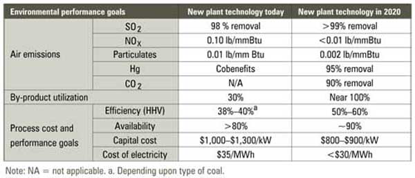
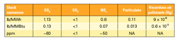
The EPA, through its management of the 1990 Clean Air Act Amendments (CAAAs), has set strict emissions performance limits for new coal-fired EGUs. Table 1 summarizes these emissions based on best available control technology (BACT).
 |
|
Table 1. EGU pollution emission performance targets. Courtesy: CastleLight Energy |
The EPA’s recent Affordable Clean Energy Rule also proposes to limit CO2 emissions from new EGUs. Table 2 summarizes the proposed efficiency targets, corresponding CO2 emissions, and unit heat rate equivalents.
 |
|
Table 2. Proposed EGU CO2 emission targets. Courtesy: CastleLight Energy |
CCS-SG EGU with Integral SO2 and NOx Control
Figure 2 illustrates a coal-fired EGU with the CCS-SG. It includes a coal-drying step coupled with a coal-gasification hybrid providing SO2 and NOx control to meet EPA air quality regulations. Limestone is added to the coal to provide the calcium necessary for sulfur capture. Particulate control is furnished with an ESP or baghouse. The CCS-SG reports improved combustion efficiency of about 6% and delivers about 10% more electricity for the same amount of coal fired, at one-third the cost of conventional FGD and SCR systems.
 |
|
2. This diagram shows an EGU unit with a CCS-SG (Clean Combustion System Steam Generator). Courtesy: CastleLight Energy |
The Figure 3 schematic illustrates the CCS process for SO2 and NOx control. It is a rather simple coal gasification hybrid (replacing conventional coal burners) and in-furnace air-staged combustion. The gasification chambers (GCs) are fabricated as studded, refractory-lined waterwalls mounted in the boiler furnace. The water-cooled refractory surfaces become coated with coal slag to provide a reliable, renewable, protective surface from the coal gasification products.
 |
|
3. This diagram shows how the CCS burner works. It utilizes a hybrid coal-gasification process. Courtesy: CastleLight Energy |
A number of CCS burners (based on unit requirements) fire pulverized coal and powdered limestone with very little hot combustion air into the GCs, creating a hot, very-fuel-rich gas as required for the CCS sulfur capture and NOx destruction processes described below. The high gasification temperatures melt the coal ash, which then drains from the GC as a slag product. The hot, fuel-rich gases of nitrogen, carbon monoxide, and hydrogen exit the GC into the furnace. A clear, bright-orange gas fills the furnace to generate steam. The furnace walls remain clean, free of slagging, fouling, and corrosive sulfur deposits.
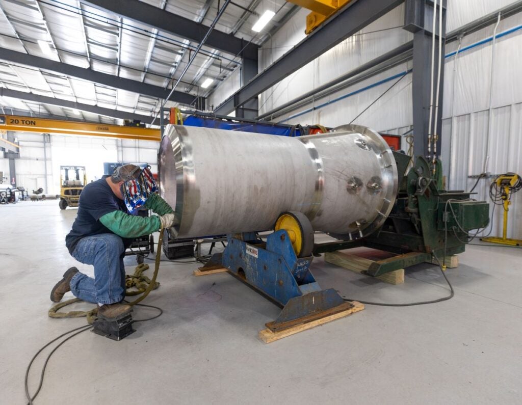
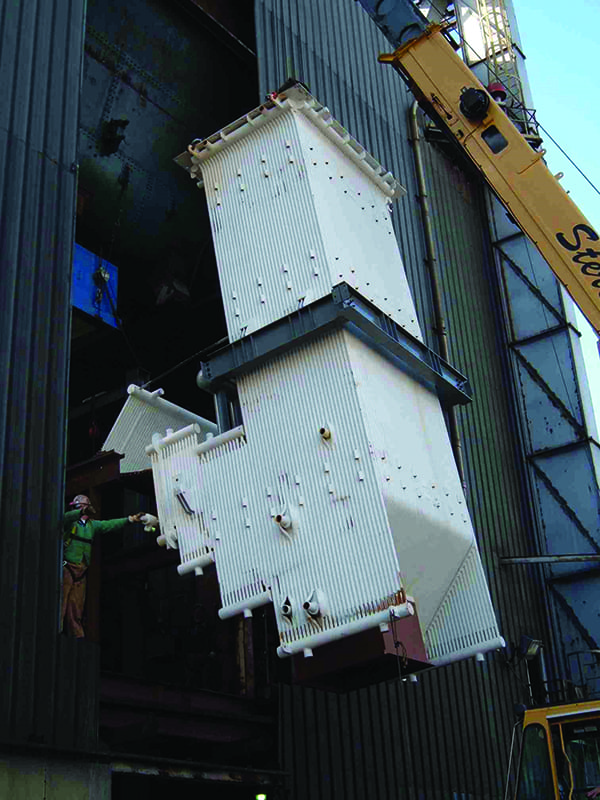
As the gases cool in the furnace (to less than 2,300F to avoid any thermal NOx formation), over-fire air (OFA) is staged through multiple ports to complete the combustion of carbon monoxide to CO2 and hydrogen to water. The gases then exit the furnace into the boiler’s back-pass superheater section. Figure 4 shows a CCS-GC installed on a 30-MWth industrial stoker boiler.
 |
|
4. A CCS gasification chamber is shown here being installed on a 30-MWth industrial stoker boiler. Courtesy: CastleLight Energy |
Sulfur Capture in Combustion
Engineers are aware that the sulfur in coal can be captured in the initial combustion step. For example, commercial circulating fluidized-bed (CFB) furnaces burn coal in a bed of sand and limestone (at about 1,600F), fluidized with hot combustion air. The CFB combustion process is fairly slow—several seconds—and requires high-horsepower, high-pressure air blowers to circulate the fluid bed.
By comparison, the CCS combustion process is fast—fractions of a second. As the carbon is oxidized, the sulfur is released from the coal into the hot gases. The calcium (from limestone) reacts with the sulfur to form calcium sulfide (CaS), a solid particle at these temperatures.
The gasification temperatures are sufficiently hot to melt the coal ash (silica and alumina) along with the CaS, creating a liquid-glass slag product. Recall that bottle glass is a melt of silica, alumina, and calcium oxide (CaO). However, because CaS has replaced CaO in the process, the sulfur is encapsulated and bound in the slag; it cannot leach out in water. About half of the melted coal ash contacts the walls of the GC and drains into a water-quench tank as bottom ash for disposal. The remaining fine ash droplets that carry into the furnace section solidify as fly ash particulate (about 10 micron) as the gases cool to make steam.
NOx Formation and Destruction
The nitrogen in the coal (about 1%) is the major source of NOx (about 85%) from coal combustion. Thermal NOx, formed from oxidation of nitrogen at high temperatures (above 2,300F) in the furnace, comprise the balance of NOx emissions.
In the late 1970s, combustion research by Dr. A.E. Axworthy, principal scientist at Rocketdyne, confirmed that the nitrogen in coal forms NOx, or the precursors of NOx such as ammonia (NH3) and cyanide, at the same time and place as the carbon is oxidized. Further, he demonstrated that this fuel-NOx formation process cannot be avoided when firing coal, as compared to thermal NOx formation when firing natural gas.
A theory evolved to look for a process to reduce (destroy) NOx to nitrogen. A lab furnace was set up and it was determined that the CaS compound was a gangbuster NOx-destruct catalysis, especially under fuel-rich, high-temperature conditions, such as found in the CCS. This was a remarkable discovery.
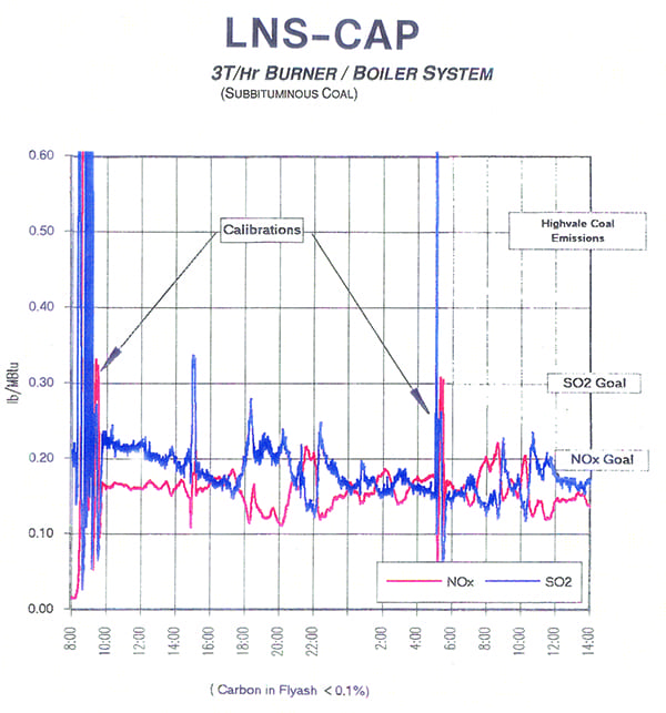
Rockwell’s new burner concept provided sulfur capture with synergistic NOx destruction all within the combustion step. An SCR catalysis and NH3 are not needed for NOx control. As important, follow-on CCS programs have demonstrated the CCS NOx control process operates reliably from initial startup to full-load operation (Figure 5), generally reporting about 50 ppm, to meet a strict less than 0.07 lb NOx/MMBtu emission rate.
 |
|
5. This chart is from a Low NOx/SOx Coal Applications Pilot (LNS-CAP) project, which demonstrated emissions performance of this hybrid gasification scheme while firing Western low-sulfur Powder River Basin-type coals. It achieved SO2 of less than 0.2 lb/MMBtu (about 100 ppm), NOx of less than 0.15 lb/MMBtu (about 110 ppm), high efficiency (loss on ignition of less than 0.1%), and near-zero SO3. Courtesy: CastleLight Energy |
Coal Drying to Improve EGU Efficiency
Raw Powder River Basin (PRB) coal quality is about 8,560 Btu/lb and includes about 30% water. This moisture carried through the furnace results in a significant latent-heat-of-water energy loss. However, with a simple coal-drying step, PRB quality is improved by about 25% to roughly 10,700 Btu/lb, resulting in about 3% higher combustion efficiency, reduced coal consumption, lower operating costs, and lower CO2 emissions.
Typical large (500-MW) coal-fired EGUs consume about 10,000 tons of coal per day. Coal drying programs such as dry fining require time (about 30 minutes) to dry the coal, resulting in very large equipment investments necessary to supply sufficient coal. Further, dried PRB coal cannot be stored—it is a very reactive fuel, and for safety must be consumed immediately.
Conventional direct-fired EGUs use coal mills to grind the coal to a talcum-like powder using hot (about 600F) primary air from the air preheater as a sweep-gas to convey the powdered coal from the mill to the coal burners on the furnace. As noted, the CCS gasification process uses very little combustion air as compared to typical coal burners, so an indirect coal-fired system is used, directing the coal from the mill to a small baghouse to remove the sweep-gas and collect the powdered coal in a hopper.
Rather than use hot primary air for the sweep-gas, the CCS uses hot (about 600F) inert flue gas (oxygen less than 10%) drawn from the EGU’s exhaust, which is possible because the CCS exhaust gases have near-zero SO3. As the coal is pulverized, the hot sweep-gas evaporates the coal’s surface moisture (from about 30% to about 7%), safely drying the coal particles in about one second (Figure 6).
 |
|
6. The CCS coal drying process is shown here. It uses hot inert gasses drawn from the EGU’s exhaust to reduce coal surface moisture from about 30% to about 7%. Courtesy: CastleLight Energy |
The sweep-gas conveys the pulverized coal and limestone from the mill to a small baghouse (Figure 7) added to each coal mill. In the baghouse, the powdered coal is separated from the wet sweep-gas. The dry powdered coal is then collected in the baghouse hopper, and directly metered and conveyed to the CCS burners as required to meet EGU firing loads. The now cool and wet sweep-gas from the baghouse is rerouted around the furnace to the EGU’s exhaust.
 |
|
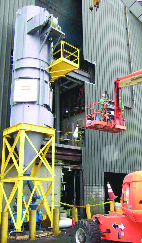
7. This image shows a coal sweep air separator installed on a pilot unit. Courtesy: CastleLight Energy |
CCS-SG Is a Viable Technology
It is generally accepted by the utility industry that the best Rankine Cycle heat rates (Btu/kWh) for EGUs require supercritical, high-temperature, high-pressure steam boilers. These units operate best at full loads, are limited in turn-down, and require expensive, exotic steels to survive the high temperatures. Also, today’s electric grid requires EGUs that are capable of rapid response to match loads that meet load variation from renewable solar and wind generation.
However, the proposed CCS-SG is a subcritical boiler design, featuring supercritical heat-rate performance (in excess of 42% efficiency, better than 8,100 Btu/kWh). This design can provide wide load following—from low-load, overnight operation at about 25% of maximum continuous rating (MCR) with the ability to ramp up at about 4% MCR per minute to 100% MCR operation.
The subcritical CCS-SG is sized for about 350 MWe and operates from 2,400 psig to 2,520 psig, or as close to these pressures as can be done safely. The CCS-SG includes one or two reheat steam cycles to the turbine and an efficient feedwater heater system, for example, a total of eight feedwater heaters, one being the deaerator. Natural gas, supplemented with coal co-firing, is used for startup and warmup duty in about five hours.
The CCS-SG is a compact heat-recovery furnace/steam generation section that includes multiple stages of OFA. There are six 50 ton/hr coal pulverizers and coal-drying systems—one for each GC and its CCS burners. Near the furnace bottom are six CCS GCs (three located on each side of the furnace), each GC directs its hot gases into the furnace section and each has four down-fired, entrained-flow, CCS burners, for a total of 24 CCS burners. Each CCS burner is sized for about 150 MMBtu/hr.
The hot gases from the GC must make a 180-degree turn to enter the furnace. Each GC includes water-cooled slag screens that remove half of the liquid ash, which then drains into a water-quench tank under the GC. A wet-drag-link system conveys the ash/slag into a dumpster for disposal. This slag product has commercial value of about $3/ton for roof grit, and it is suitable for grit-blasting metal, as it doesn’t cause silicosis.
The CCS-SG can fire PRB subbituminous and lignite—low-sodium coals—to meet the strict EPA air quality regulations for a new coal-fired EGU, that is, SO2 emissions of less than 0.13 lb/MMBtu or about 66 ppm and NOx emissions of less than 0.07 lb/MMBtu or about 50 ppm. A baghouse is required for fly ash particulate control (less than 0.13 lb/MMBtu).
To optimize the EGU efficiency objectives, the steam turbine generator and other large rotating equipment is designed for high-efficiency service. CastleLight recommends the design criteria presented in the report titled “Program for Coal-fired Electrical Generation Units to Maximize these Objectives: – Boiler Efficiency – Electrical Generation (kW) for a Given Fuel Rate (Btu/hr), – Reliability and Availability, as well as Operability,” written by Dr. Melvin Giberson, president of TRI Transmission and Bearing Corp.
CCS-SG Commercialization Path
As mentioned, the cost for a coal-fired EGU includes FGD and SCR pollution emissions control. As the 21st century CCS-SG does not require this equipment, it is expected to save an EGU about 35% compared to conventional boiler technology.
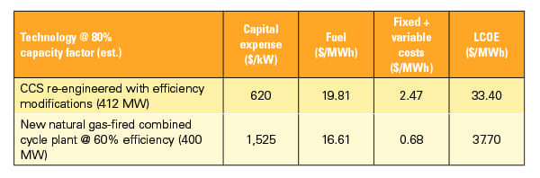
For commercialization, CastleLight recommends forming an investor group to acquire a PRB coal-fired power plant (100 MW to 200 MW with its Title V permit current). This organization can then re-engineer the plant with CCS technology. As an emissions reduction program, the CAAAs provide construction permits with waivers of New Source Performance Standards (NSPS) and Prevention of Significant Deterioration (PSD) with no New Source Review (NSR) trigger. Table 3 shows that such a CCS re-engineering project can make a coal-fired EGU competitive with that of a new natural gas-fired combustion turbine in combined cycle mode with gas at $3.00/MMBtu or higher.
 |
|
Table 3. This table compares the levelized cost of electricity (LCOE) of a CCS re-engineering project and a new natural gas-fired combined cycle plant. Courtesy: CastleLight Energy |
With commissioning, testing, and tuning for optimum performance, and a few years of operation, the first CCS-SG EGU may then be sold to recover the investment. Thus, proving CSS-SG as a commercial system for use worldwide. ■
—Keith Moore is CEO of CastleLight Energy Corp., an Oxnard, Calif.-based technology management firm (castle-light.com).