Heat exchangers are important in all thermal power plants and in many other applications. If not properly operated and maintained, a variety of failures can occur, resulting in downtime, reduced efficiency, and higher costs. However, there are a number of steps you can take to keep heat exchangers in top condition.
Heat exchangers are used in many critical processes to protect other valuable manufacturing equipment, optimize energy consumption, and reduce associated operating costs. A properly selected, installed, and maintained heat exchanger can help enhance the reliability and efficiency of a fluid system.
However, although heat exchangers provide high operating efficiency, they are exposed to specific risks in power plants, which can lead to costly downtime if left untreated. There are three common types of heat exchanger failures that can occur:
- ■ Mechanical failures
- ■ Scale, mud, and algae fouling
- ■ Chemically induced corrosion
Mechanical Failures
Mechanical failures can take many different forms including, but not limited to, metal erosion, steam or water hammer, and thermal expansion and cycling.
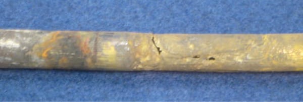
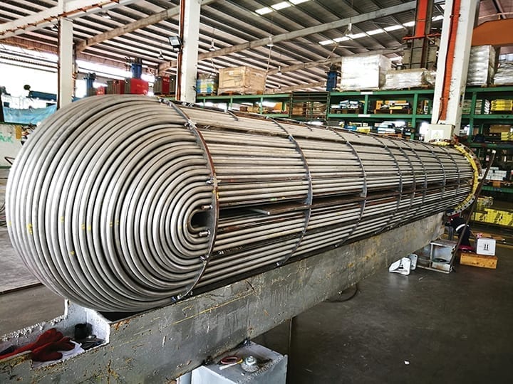
Metal Erosion. Excessive fluid velocity on either the shell or tube side of the heat exchanger can cause damaging erosion, potentially removing the tube material’s protective film, exposing fresh metal to corrosion. The areas most prone to erosion are the U-bend of U-tube heat exchangers (Figure 1) and tube entrances. Tube entrance areas can experience material loss when excessive high-velocity fluid from a nozzle is divided into much smaller streams as it enters the heat exchanger. When excessive velocity occurs at the entrance area of tubes, it typically produces a horseshoe-shaped erosion pattern.
 |
|
1. A U-tube bundle is shown here being fabricated at a mechanical workshop. Source: Shutterstock |
The maximum recommended velocity in the tubes and entrance nozzle depends on many variables, including tube material, fluid handled, and temperature. Materials such as steel, stainless steel, and copper-nickel withstand higher tube velocities than copper.
Erosion problems on the outside of tubes can occur with impingement of wet, high-velocity gases, such as steam. Wet gas impingement is controlled by oversizing inlet nozzles or by placing impingement baffles in the inlet nozzle projection area. Typical shell-side nozzle velocity limits to prevent impingement erosion on the outside of tubes can be established with the following:
density x velocity x 2 ≤ 1,500 lbm/ft2-second
where density is entered in lbm/ft3, and velocity is the shell nozzle velocity in ft/second.
Steam or Water Hammering. Pressure surges or shock waves caused by the sudden and rapid acceleration or deceleration of a liquid can cause steam or water hammer. The resulting pressure surges can reach 20,000 psi, which is high enough to rupture or collapse the tubing in a heat exchanger.
In a water/steam heating application, damaging pressure surges can result in an interruption to the flow of cooling water. The stagnant cooling water is heated beyond its boiling point to generate steam, and the resumption of the flow causes a sudden condensing of the steam, which produces a damaging pressure surge or water hammer.
Therefore, cooling water flow should always be started before heat is applied to a heat exchanger. Modulating control valves are also preferable to fluid flow control valves, which open or close suddenly and cause water hammer. If condensable fluids are handled in either the shell or tubes, vacuum breaker vents can help prevent steam hammer damage resulting from condensate accumulation.
The installation of properly sized steam traps with return lines can help eliminate steam hammer by preventing condensation from accumulating in the shell. Plant managers should also ensure that the lines are pitched to a condensate receiver or condensate return pump.
Thermal Expansion and Cycling. Accumulated stresses associated with repeated thermal cycling or expansion can result in tube failure. This is more likely to occur with a straight-tube fixed-tube-sheet design, where the tubing is fixed between the two tube sheets and cannot expand or contract.
This problem intensifies as the temperature difference across the length of the tube increases, causing tube flexing, which produces a stress that acts additively until the tensile strength of the material is exceeded and cracks. The crack usually runs radially around the tube, and often results in a total break. In other cases, the crack occurs halfway through the tube and runs longitudinally along it. Failures due to thermal expansion of fluids are most common in steam-heated exchangers.
A U-tube-type heat exchanger, which allows the tubes to freely expand and contract, is one solution. Relief valves can also be installed in the heated fluid system to prevent this kind of failure. It’s advisable to provide some means to absorb fluid expansion. For example, installing a tank in the heated fluid system prevents periodic discharge of relief valves, which results in a loss of system fluid and places an undue burden on the valve.
Scale, Mud, and Algae Fouling
Various marine growths or deposits can leave a film or coating on the surfaces of heat transfer tubes, which act as an insulator restricting heat flow, causing tube wall temperatures to rise and corrosion to increase.
Scale is the result of dissolved minerals precipitating out of heat transfer fluids. The solubility of these minerals is altered by forces within the heat exchanger, such as changes in temperature or chemical reactions. For example, when calcium bicarbonate is heated, carbon dioxide is released and the material is reduced to calcium carbonate, which precipitates and coats heat transfer surfaces.
The rate of precipitation is reduced with increasing fluid velocity. Fluid velocity must be matched to the tube material’s ability to withstand the erosive effects of velocity.
Suspended solids are usually found in the form of sand, iron, silt, or other visible particles in heat transfer fluids. If velocities are not high enough to keep them in suspension, particles settle out. Suspended solids are very abrasive to tubing and other heat exchanger parts. If abrasive suspended solids are handled in the heat exchanger, fluid velocity should be kept low enough to prevent erosion.
Algae and other marine growths are a serious problem if they get in a heat exchanger. In many cases, the environment in the heat exchanger is conducive to rapid proliferation of the algae or other marine growths, which restrict flow and impede heat transfer.
Chemical algaecides, such as chlorine, are effective in controlling algae and other marine growths. Always check to ensure any chemical treatment is compatible with the materials of construction. High fluid velocities also discourage their attachment and expansion.
Chemically Induced Corrosion
These failures result from the complex chemical interaction between the materials of the heat exchanger and the fluids circulated through it, and numerous other system controls. Common types of chemically induced corrosion failures include:
- ■ General corrosion
- ■ Pitting corrosion
- ■ Stress corrosion
- ■ Galvanic corrosion
General Corrosion. This type of corrosion is characterized by a relatively uniform attack over the tube, tube sheet, inlet bonnet/channel, or shell. There may be no evidence that corrosion is taking place.
Fairly stable aggressive conditions generate this type of attack. Low pH (less than 7) combined with either carbon dioxide or oxygen can produce this attack on copper causing a blue or bluish-green color to appear on the inside of tubes. Various chemicals, such as acid, also produce this type of metal loss.
Selecting a material with adequate corrosion resistance for its environment, along with using proper treatment chemicals, maximizes heat exchanger life. It is important to keep in mind the various factors working in combination—you may need to consult a metallurgist.
Pitting Corrosion. Localized pitting frequently occurs in both ferrous and nonferrous metals. It results from the electrochemical potential set up by differences in oxygen concentration within and outside of the pit, frequently referred to as a concentration cell. The oxygen-starved pit acts as an anode and the unprotected metal surface serves as a cathode, resulting in a small number of pits, any of which can cause a heat exchanger failure.
Pitting corrosion is most likely to occur during shutdown periods when there is no flow and the environment is most suitable for the buildup of concentration cells. The susceptibility to pitting corrosion is further enhanced by scratches, dirt or scale deposits, surface defects, breaks in protective scale layers, breaks in metal surface films, and grain boundary conditions.
To prevent pitting corrosion, ensure materials of construction are suitably selected, and properly clean and prepare the heat exchanger for shutdown periods.
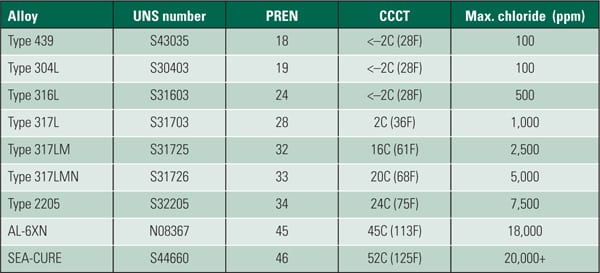
Stress Corrosion. This form of corrosion attacks the grain boundaries in stressed areas. Heat exchanger tubes usually have both avoidable and unavoidable residual stresses. These stresses are the result of drawing or forming the tube during manufacture, forming U-bends, or expanding the tubes into tube sheets. Failures from this corrosion take the form of fine cracks, which follow lines of stress and material grain boundaries. Chloride ions can cause stress corrosion on stainless steel tubes, while ammonia can cause stress corrosion cracking on copper or copper alloy tubes.
Keeping tube wall temperatures below 115F (calculated with maximum, not average fluid temperatures) prevents stress corrosion cracking problems with a chloride ion concentration up to 50 ppm. Copper-nickel alloys have good resistance to stress corrosion cracking and should be used in applications where low concentrations of ammonia are expected.
Galvanic Corrosion. Galvanic corrosion occurs when dissimilar metals are joined in the presence of an electrolyte, such as acidic water. It usually produces a higher rate of reaction on the less noble metal, causing it to corrode quickly.
Metals grouped together have fewer tendencies to produce galvanic corrosion. When two metals from substantially different groups are coupled together in an electrolyte, the result is substantial corrosion of the less noble metal. Typically, a voltage difference of greater than 0.2 volts suggest a galvanic risk, and the further apart the metals are, the greater the risk of corrosion. Consider not only the different materials for the heat exchanger components but also for piping and fittings connected to the heat exchanger.
With a carefully selected and maintained heat exchanger, operators can stay ahead of issues. What’s more, smart specification and maintenance will optimize fluid systems for reliability, efficiency, and importantly, peace of mind.
—John Boyer (john.boyer@xyleminc.com) is heat transfer commercial team manager for Xylem, and Jim Klimek (jim.klimek@xyleminc.com) is heat transfer product/business development manager for Xylem.