Modern heat recovery steam generator (HRSG) design must balance operating response with the reduction in life of components caused by daily cycling and fast starts. Advanced modeling techniques demonstrate HRSG startup ramp rates can be accelerated without compromising equipment life.
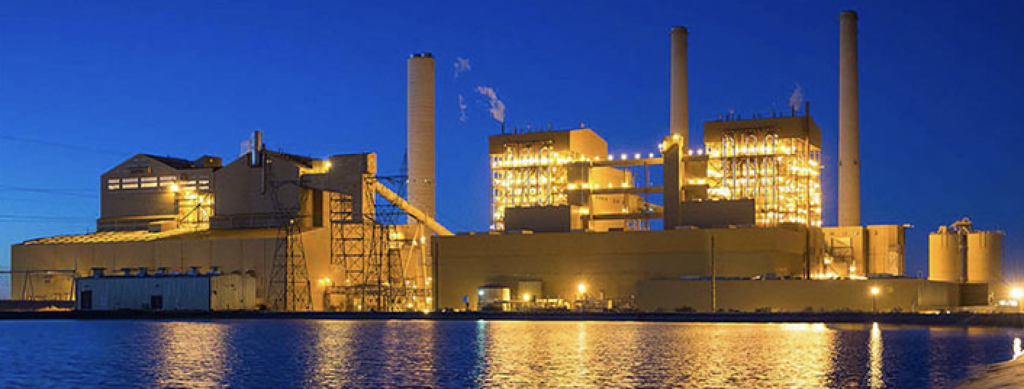
Natural gas–fired combined cycle (NGCC) technology is an attractive choice for new power plants because of its high fuel efficiency, operating flexibility (quick starts and rapid load changes), relatively short planning and construction period, and relatively low emissions and capital cost.
The large-scale installation of wind farms and solar electric installations has created a new opportunity for advanced NGCC technology used as backup to these intermittent resources. A combined cycle plant can quickly increase (or decrease) its electric output to replace that lost during periods when the wind doesn’t blow or the sun doesn’t shine. However, the capability of the combustion turbine (CT) to perform rapid load changes and fast startups must also be reflected in the design of the heat recovery steam generator (HSRG).
NGCC plants used to back up renewable sources will experience increased cycling operation. The most critical factors during startup are the rapid increase of key operating parameters, including temperature, pressure, and mass flow. In the past, the cold startup time of a typical HRSG ranged from 45 minutes to 2 hours—or more. During the startup period, HRSG components, especially the steam drum, are subject to high thermal stress that is generated by the uneven distribution of temperature. The increased level of component stress often has an adverse impact on component life, often requiring upgraded materials.
Earlier work identified the effects of cyclic operation on the HRSG, particularly the life of key components subjected to thermal transients. The design of modern HRSGs includes many features to limit the stresses resulting from these thermal transients. Increased boiler operating pressures have required HRSG designers to increase component thickness to resist the added pressure stress. However, the more robust components cause an increase in the thermal transient stress experienced by the component. Dynamic thermal transient analysis, incorporating dynamic modeling and thermal hydraulic analysis, can be used to determine the component stresses and resulting fatigue life of components. The most highly affected components include superheater and reheater outlet headers and manifolds, high-pressure steam drum, downcomers, and risers.
Customer demand for greater NGCC operating flexibility has led to new designs—for example, GE’s recent FlexEfficiency combined cycle plant designs. (See “GE Develops FlexEfficiency 50 for Increased Operational Flexibility” in the December 2011 issue, online at https://www.powermag.com.) The FlexEfficiency design is able to rapidly increase or decrease its power output in response to fluctuations in wind and solar power, enabling the connection of more renewable resources to the power grid. One of the key features of this new NGCC configuration is its ability to reach full load in less than 30 minutes from a cold start.
Improving Plant Operations
Optimizing operation of the HRSG within an NGCC plant requires a combination of robust component design, rigorous calculation methodologies, and implementation of advanced control systems. All three requirements must be addressed in every HRSG design.
For example, the performance of an HRSG may not be optimal due to overly conservative operation in order to extend component life. The result is often inconsistent or low ramp rates used throughout the startup, resulting in relatively long startup times. In such cases, faster startup times are possible while maintaining acceptable fatigue cycle life of the HRSG components. The case study presented later in the article will demonstrate the analysis used to select an appropriate ramp rate.
Optimizing operation of the control system can also accelerate NGCC startup by providing a more consistent HRSG ramp rate. The typical control system can be improved in several areas:
- Ramp up the HRSG immediately upon CT startup. Send a small amount of CT exhaust gas through the HRSG while sending the remainder to a bypass stack.
- Replace manual adjustments of the bypass damper during startup with automatic control. Incorporate feedback philosophy, using the desired steam drum ramp rate to control the bypass damper.
- Minimize CT hold time during HRSG startup hold. Hold the CT with the inlet guide vane wide open at the allowed maximum temperature for the HRSG.
- Optimize the use of bypass damper to help accelerate CT startup.
This list is not exhaustive but must be added to or modified for plant-specific details. However, the common factor is that any change in operation must be thoroughly assessed to avoid any potential impact on HRSG component fatigue life. A rigorous analysis methodology must be employed to quantify the impact of operational changes and when providing guidance on the operating methods to be used by plant staff.
Analysis Methodology
The analysis methodology is complex and must be adapted to site-specific equipment and requirements. It includes an overall NGCC plant simulation—including HRSG, CT, and steam turbine (ST); evaporator sub-model simulation; and fatigue cycle life analysis incorporating the advanced startup methodology and features, as described above.
System Analysis. First, ProTRAX software is used to simulate the overall system that includes the evaporator, superheater, economizer banks, duct burner, feedwater system, CTs, and STs. The CT is modeled as a boundary condition module that provides the CT outlet conditions (temperature and flow rate) for the HRSG model. The ProTRAX model dynamically calculates steam temperatures, pressures, and flow rates as functions of time, based on a given plant startup procedure. The analysis in the case study described in the next section focused on the cold and warm HRSG startup scenarios because these have the greatest impact on the operation and fatigue cycle life.
Evaporator Analysis. Next, a one-dimensional THTNET (Thermal-Hydraulic Transient NETwork) model of the evaporator downcomers, risers, feeders, heat transfer tubes, and steam drum is constructed using Foster Wheeler’s proprietary in-house software. The evaporator flue gas inlet temperature and flow rate and steam-side drum pressure are obtained as functions of time from the HRSG system model. Of primary interest are individual riser outlet conditions (temperature, flow rate, steam quality, and heat transfer coefficient) and drum water conditions (temperature and level).
Cycle Life Calculations. Finally, a screening analysis of the headers and drums is used to determine the most critical components from the consideration of thermal cycle fatigue. Previous analyses of similar HRSG configurations by Foster Wheeler have determined the riser connections to the steam drums to be the most susceptible areas during startup transients. Fatigue life evaluations are performed for these riser-to-drum connections.
A finite element analysis of the drum-to-riser junction is performed for three startup conditions, at two ramp rates for each condition. These startup conditions are simulated by a transient thermal analysis, followed by a stress analysis. A general purpose finite element analysis program is used in these calculations. The variation of steam temperature and the film coefficients applied during the transients is obtained from dynamic analysis of the HRSG and the THTNET modeling results.
Temperature and stress results obtained by the finite element analysis are used to determine the fatigue life of the selected HRSG components. The analysis presumes a number of assumptions. For example, all welds are assumed to be ideal, full-penetration welds. The analysis considers only elastic material effects, and any effects due to high-temperature elastic-plastic creep are not included in the present analysis. Local thermal stresses are analyzed, and the stresses due to thermal expansion of tubes and pipes are not included. The deadweight stresses due to loads from the piping on the nozzle were neglected because proper design can minimize these loads.
The temperature and thermal stress calculations obtained by the finite element analysis are then post-processed to determine the fatigue life of the selected components. Pressure stresses are added to the thermal stresses. The Von Mises equivalent of the total stresses is used in the fatigue calculations.
The fatigue life evaluation is based upon methods described in the American Society of Mechanical Engineers (ASME) Boiler and Pressure Vessel Code, Section VIII, Division 2. The fatigue properties of the materials are obtained from the ASME code. The results present the fatigue damage incurred for each condition. Total fatigue damage over the plant life can be determined be summing the number of cycles of each type of startup, multiplied by the fatigue damage of that particular startup condition.
Application Example
To illustrate the methodology, the impact of fast startup on an existing HRSG design and its normal operation was evaluated, including effects upon natural circulation, thermal performance, and cyclic fatigue life. The purpose of the analysis, abstracted from a recently completed study, was to provide guidance for improving startup times, consistent with minimal impact upon cycle life. Dynamic simulation and life-cycle analysis were performed on the plant’s HRSG, which was designed and supplied by Foster Wheeler. The primary goal of the analysis was to accelerate the cold startup, above the rates previously used by the plant (an average of 80F/hr), while continuing to maintain acceptable component cycle life.
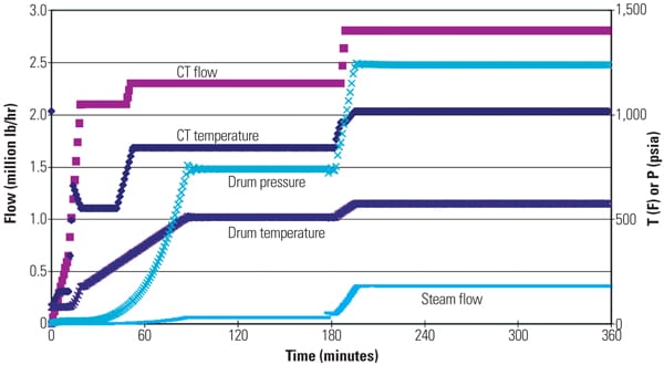
System Analysis. A model of the existing operating HRSG was created using ProTRAX simulation software. The case study plant is equipped with a single-pressure HRSG with supplementary firing and a bypass damper. The HRSG is also configured with an economizer and primary and secondary superheaters. Data collected during a typical cold HRSG startup is illustrated in Figure 1.
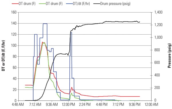 |
| 1. Typical cold HRSG startup. The red and green curves show the top-to-bottom drum temperature differential at the left and right ends of the drum, respectively. The blue curve describes the rate of change of the drum water temperature (F/hr), which is one of the key parameters controlled during HRSG startup. The black curve illustrates steam drum pressure change during startup. Source: Foster Wheeler North America Corp. |
For more accurate control, another control loop was added to the model to maintain a given drum temperature ramp rate, which was achieved by manipulating the opening of the gas diverter damper in conjunction with opening the steam supply valve. Using this control model, different startup scenarios were simulated and evaluated for different initial conditions and different CT and HRSG ramp options. Parameters affecting HRSG startup performance include the CT ramp rate and hold conditions, HRSG ramp rate and startup condition, and CT and HRSG initial conditions.
To reduce the time for cold startup, the rate of drum water temperature rise was increased to 300F/hr, as shown in Figure 2. During this scenario, part of the hot flue gas from the CT was diverted to the HRSG at the beginning of startup, and the ST and CT were ramped together to full load. To minimize plant startup time, a properly tuned control loop maintained the ramp rate at the maximum allowable value. Fast ramping of the CT and holding it at a high loading condition will generate more power during startup. However, the CT ramp rate is limited by the dynamic response of the HRSG to generate steam and to maintain the tube metal temperatures below the design limits.
 |
| 2. Cold startup. The dynamic response of the modeled NGCC during a cold startup is illustrated. Source: Foster Wheeler North America Corp. |
Evaporator Analysis. THTNET is an in-house computer code developed by Foster Wheeler that performs one-dimensional transient thermal/hydraulic analysis of a flow heat transfer network through finite difference techniques. The program has the capability to model system components such as tanks, shell-tube heat exchangers, and control valves.
The THTNET model of the analyzed high-pressure (HP) evaporator is shown in Figure 3. It consists of 170 steam/water nodes and 120 flue gas nodes, for a total of 290 nodes. The model begins at the steam drum, follows the fluid flow through the downcomers, into the transfer piping, up through the feeders, into the feeder headers, through the heat transfer tubes, into the riser header, through the risers, and into the steam drum and separators. Each individual riser and feeder is modeled.
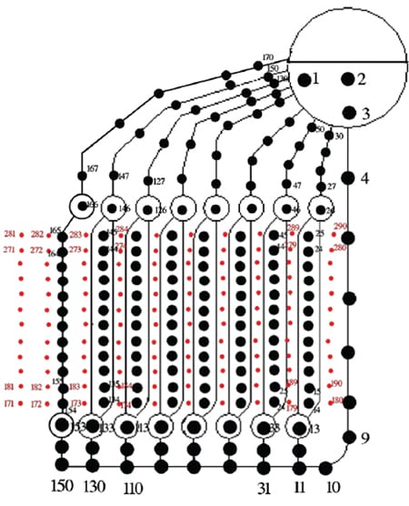 |
| 3. Evaporator model. The nodes selected in the high-pressure evaporator for the THTNET model are illustrated. The evaporator consists of many pipe loops connected to the steam drum in parallel. Courtesy: Foster Wheeler North America Corp. |
The Chisholm correlation is used to determine water/steam slip. The modified Martinelli-Nelson correlation is used to determine two-phase pressure drop. The thermal inertia of the tubes and fins is simulated by specifying the actual tube inside and outside radii and multiplying the metal density by the ratio of the finned tube weight (tube + fins) to the bare tube weight.
Heat transfer coefficients in the riser are calculated as the greater of the natural convection and forced convection (liquid) coefficients. The forced convection heat transfer coefficients are calculated from the Dittus-Boelter correlation for fully developed turbulent pipe flow. The natural convection heat transfer correlation is calculated from the turbulent vertical wall correlation.
Drum and Downcomer Analysis. A one-dimensional model was constructed of the drum using the in-house Foster Wheeler computer code CONDRAD. Heat transfer coefficients in the lower drum (below the water level) are calculated from the turbulent horizontal wall correlation (cold plate facing up). The heat transfer coefficient in the upper drum (above the water level) is calculated from the laminar film condensation correlation.
Boundary Conditions. The evaporator flue gas inlet temperature and flow rate and drum pressure are obtained as functions of time from the HRSG system model. Feedwater flow rate is added to maintain the drum water level near the normal water level by the model controller.
A cold startup with the 300F/hr drum water temperature rise was one of the scenarios analyzed. Figure 4 presents the riser outlet quality versus time for some of the eight risers for this scenario. The first riser is on the cold end, while the eighth one is on the hot end. Figure 5 presents internal heat transfer coefficients for the risers and the drum.
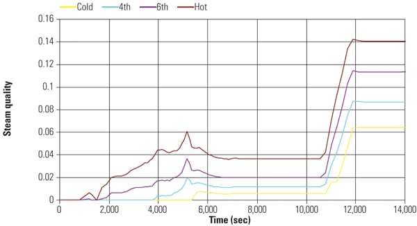 |
| 4. Riser outlet quality. The steam quality in different riser outlets is illustrated during a cold plant startup using a 300F/hr drum water temperature rise. Saturated steam has a quality of 1.0. Source: Foster Wheeler North America Corp. |
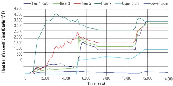 |
| 5. Efficient heat transfer. The internal heat transfer coefficients for the risers and the drum during the same startup scenario described in Figure 4 are shown. Source: Foster Wheeler North America Corp. |
Cycle Life Calculations. The HRSG is subjected to cyclic load changes, especially during accelerated startups. The temperature gradient that exists between the inside diameter intersections of the drum riser and the drum outside diameter causes thermal stresses in the component and combines with pressure stresses (the steam drum is at operating pressure) to cause fatigue damage. The maximum Von Mises stresses of the combined (temperature and pressure) load case were used to determine the fatigue life for each case, as well as the fatigue damage per cycle. Total stresses, using the combined thermal and pressure loads, were used in the fatigue calculations. The fatigue life evaluation is based on the analysis methodology described in ASME Boiler and Pressure Vessel Code, Section VIII, Division 2, Appendix 5.
A preliminary screening analysis of the headers and drums was made to determine the most critical components of the HRSG from the consideration of thermal cycle fatigue. The components consisted of HP headers and drums and their connection to thin-walled tubing and piping. The riser connections to the steam drums were found to be the most highly stressed areas during a cold startup transient.
Based on the results of the preliminary screening analysis, the connection between the 5-inch riser and the drum was identified as the component and location most susceptible to thermal cycle fatigue. The thermal transient models were run to determine the temperature distribution in the drum-riser connection, up to the end of the main startup ramp. The thermal fatigue analysis that follows is focused on this particular drum-riser connection.
Four startup transient scenarios were selected for analysis of the drum-riser connection using a general purpose finite element program:
- Cold startup at 200F/hr
- Cold startup at 300F/hr
- Warm startup at 200F/hr
- Warm startup at 300F/hr
Each startup condition was simulated by a transient thermal analysis, which was followed by a stress analysis at the drum-riser connection at the specific time during startup when the maximum thermal stresses occurred. The stress analysis included the combined effects of thermal and pressure loadings.
The temperature and stress results obtained by the finite element analysis were then used to determine the fatigue life of the selected HRSG components. The variation of steam temperature and pressure, and the heat transfer film coefficients during the various startup conditions, were obtained from the dynamic analysis of HRSG and the THTNET modeling results. Results of the transient thermal stress analysis (temperatures and stresses) of the drum-riser connection for cold startup with 300F/hr ramp rate are shown in Figures 6 and 7.
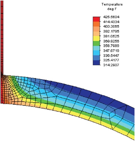 |
| 6. Worst-case temperature. The partial section view shows the wall of the drum on the left and the tube wall to the right. The maximum drum riser temperature experienced during each startup transient was found at 5,351 seconds into the startup. Source: Foster Wheeler North America Corp. |
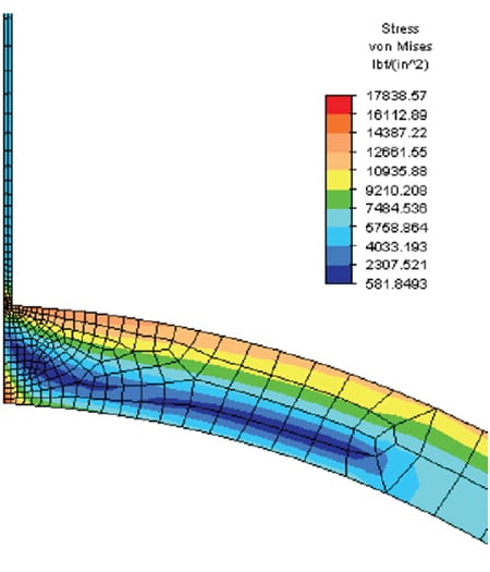 |
| 7. Worst-case stress. Under the same conditions described for Figure 6, the worst-case drum-riser stress at 5,351 seconds into the startup is illustrated. Source: Foster Wheeler North America Corp. |
Determine Allowable Fatigue Cycles. The transient thermal stress analyses just presented focused only on the startup portion of the cycle for a single component, the drum-riser connection. The HRSG experiences a variety of other transients, including cold starts, warm starts, shutdowns, and rapid load changes. In evaluating the fatigue life of one or more components, the designer must consider the stresses over the entire cycle, which vastly complicates the analysis.
For this case study, the shutdown portion of the cycle was also considered in determining the fatigue life of the component. To bracket the fatigue damage results, two scenarios were considered: a smooth shutdown and a shutdown that is as severe as a fast startup. For a smooth shutdown, it is assumed that the metal temperatures drop gradually over a long period of time without inducing significant additional stresses. In this case, the stress range is equal to the startup maximum stress value. For the case of a shutdown as severe as startup, it is assumed that the thermal stresses are reversed and, thus, the total stress range is double the maximum stress value during startup.
The effects of local structural discontinuities must also be accounted for in the fatigue analysis. While the finite element model does account for some of the geometric stress concentration effects, an additional factor is included to account for discontinuities (such as weld connections and surface irregularities) that are not included in the model. A conservative fatigue strength reduction factor of 5 was applied to the finite element stress results.
The smooth shutdown case assumes the situation in which the HRSG is “bottled up,” to maintain temperature and pressure. The severe shutdown case represents an operating upset, including, for example, a significant post-purge through the HRSG during CT shutdown. Both smooth and severe shutdown cases were paired with the cold and warm startup cases (200F/hr to 300F/hr) to form a complete startup-shutdown cycle.
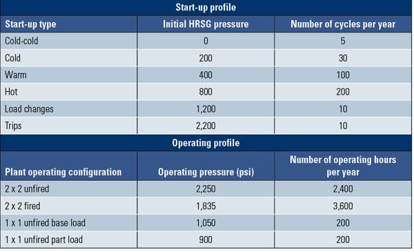
In actual operation, the HRSG experiences a combination of different startup types (including cold, warm, hot, load changes, and CT simple cycle). In order to accumulate the damage caused by the multiple types of startups, it is useful to look at fatigue damage per cycle for each startup type. Normally, cold and warm startups are the largest contributors to reduced HRSG fatigue life. For this case study, a typical annual plant startup/shutdown distribution was used (Table 1).
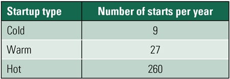 |
| Table 1. Typical distribution of annual plant startups. Source: Foster Wheeler North America Corp. |
The effect of the shutdowns must be included in the assessment of the total damage for each cycle type investigated. In summing the fatigue damage per cycle associated with each type of startup, assumptions must be made about the nature of each corresponding shutdown. There is a significant difference in the damage per cycle for smooth versus severe shutdown. As a part of this work, several different shutdown assumptions were evaluated, including the following conservative cases. The “conservative case” assumes that each shutdown is as severe as the startup. Alternatively, a “realistic severe case” was examined, where 75% of the shutdowns are severe and 25% are smooth. This analysis focused on the effects of the cold and warm starts, neglecting the fatigue life contributions of the hot restarts and load fluctuations.
The top portion of Table 2 presents the results of the “realistic severe case.” The predicted component life, under the assumption that shutdowns are 75% severe and 25% smooth, are shown. The bottom portion of Table 2 reflects the “conservative case,” which shows a corresponding predicted component life under the assumption that all shutdowns are as severe as the startups. The life shown in these tables corresponds to the time when total fatigue damage equals 100% and crack initiation (leading to tube failure) is predicted. It should be noted, however, that ASME design fatigue curves, which are the basis for this analysis, include an additional safety margin to account for material property variations.
The fatigue life predictions show that an acceptable component life is achievable even with accelerated HRSG startup. After adding more advanced HRSG controls for the HRSG, the plant startup time was reduced by up to a third with an acceptable component life.
— Horst Hack (horst_hack@fwc.com), Zhen Fan (zhen_fan@fwc.com), and Andrew Seltzer (andrew_seltzer@fwc.com) are with Foster Wheeler North America Corp., Perryville Corporate Park, Hampton, N.J. Javier Alvarez (francisco.alvarez@fwes.fwc.com) is with Foster Wheeler ES, Madrid, Spain.