Gone are the days when ocean or river water for once-through cooling of a new power plant was assumed to be available. Today, more than 500 fossil-fueled and 38 nuclear plants use once-through cooling. However, regulators in several states are aggressively pushing what is essentially a ban on the use of once-through water cooling, forcing a conversion to closed-cycle cooling.
The availability of open-cycle cooling water was usually the determining factor when siting a new power plant in years past. Along the coasts, seawater was available; river water was favored elsewhere. If a suitable river wasn’t available, then a cooling lake was created. Technical advances in cooling technology, often driven by emerging regulatory requirements, soon made historic cooling water sources more problematic.
By the 1970s, new plants used large-scale cooling towers for cooling a plant’s condenser. Today, plants that still rely on open-cycle cooling are exploring how to make the transition to closed cooling systems because of tightening regulatory requirements with respect to protecting aquatic life, reducing the thermal discharge into the water, and concerns about protecting water supplies.
This article focuses on evaluating power plant thermal discharges. A previous article presented many of the aquatic protection technologies available to plant owners to comply with National Pollutant Discharge Elimination System (NPDES) permit requirements (see “CWA 316(b) Update: Fish Guidance and Protection” in the October 2011 issue or in the archives at https://www.powermag.com).
Cooling Water Trends
The responsibility for meeting Clean Water Act (CWA) section 316(b) requirements to protect aquatic life and manage thermal discharges through technology-based solutions is delegated to the states. The states manage individual water discharges through the issuance of NPDES permits.
The current trend concerning revisions in NPDES permits requires reducing the amount of thermal energy rejected or reducing the cooling water outlet temperature, or both. Short of reducing plant load, reducing the thermal energy discharge is a euphemism for converting all or part of the cooling water heat rejection process from once-through cooling to one of the many closed-cooling options. The only other option is plant closure.
The challenge for designers asked to make an assessment of the feasibility and economics of a conversion from open to closed cooling is that there is no one-size-fits-all solution. Each plant presents a unique design challenge. In fact, many plant owners have received poor advice about cooling system conversions, resulting in inaccurate cost estimates, overly aggressive construction schedules, and unrealistic operational expectations. Additionally, plant owners often fail to consider their plant’s unique design and operations features and are unaware of the many new technology solutions now available.
Why Are Cooling Towers Added or Replaced?
New cooling towers are added and existing ones are replaced if the current cooling system heat rejection capability is inadequate or emerging regulatory requirements make the conversion a requirement.
In California, for example, the State Water Resources Control Board (SWRCB) adopted “Water Quality Control Policy on the Use of Coastal and Estuarine Waters for Power Plant Cooling,” which became effective Oct. 1, 2010. The policy effectively requires all 19 of the state’s coastal plants (including two nuclear plants) to transition to closed cooling to meet the state’s best technology available requirement under CWA section 316(b). Implementation plans prepared by fossil plant owners were submitted to the SWRCB on April 1, 2011, and implementation dates are under negotiation. A “Scope of Work Report” outlining consultant qualifications and study requirements for the two nuclear plants was completed on Nov. 7, 2011. Selection of the consulting engineering companies to perform the studies is pending (Figure 1).
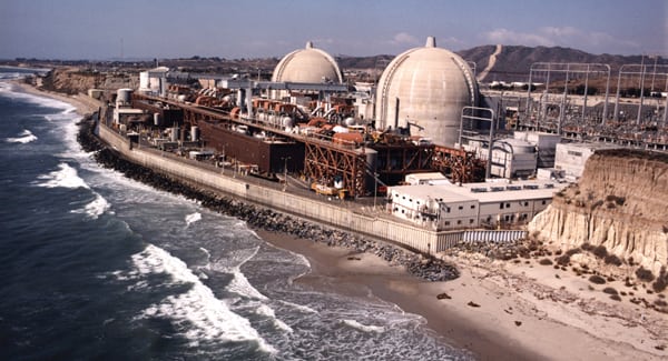 |
| 1. Cooling system conversions. California’s San Onofre (pictured) and Diablo Canyon nuclear power plants have been tasked with evaluating technologies and strategies to comply with Clean Water Act section 316(b) best technology available requirements, including the option of switching from an open cooling system to a closed or dry cooling system, among many other requirements. Source: Southern California Edison/Nuclear Regulatory Commission |
Noncoastal regions appear to be more concerned with reducing the thermal load placed on a river (million Btu/hr) and the temperature of the cooling water discharge. A good example of a plant that has made a conversion is PPL’s Brunner Island plant, located in York County, Penn. The owners of the three-unit, 1,546-MW plant invested approximately $100 million to install perhaps the largest forced-draft cooling towers in the world to reduce the thermal loading and discharge temperature to the Susquehanna River. The new cooling towers began operation in April 2010 (Figure 2).
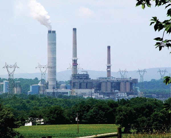 |
| 2. Cooling tower retrofit completed. PPL’s Brunner Island power plant added forced-draft cooling towers to reduce the thermal loading and discharge temperature of the cooling water discharge to the Susquehanna River. The 34-cell cooling tower requires four 3,500-hp pumps to deliver about half a million gallons every minute. The cooling towers are used during the nine warmest months of the year, from March through November. Courtesy: PPL |
Before You Make the Switch
A feasibility study for a potential once-through cooling system conversion to a closed system in order to reduce cooling water discharge temperature and thermal load begins with asking questions designed to help develop an understanding of the actual condenser heat exchange requirements and the current state of repair of plant equipment. It makes no sense to add new equipment until all the possible plant performance has been extracted from existing equipment.
Other questions will help determine if the existing cooling water system performance is marginal or if it has any surplus capacity. If a cooling water system has been the victim of inadequate maintenance, then a renovation may be cost-effective because a smaller cooling tower or a less-complicated solution may be all that is needed. What about the condition of the steam turbine? A steam turbine upgrade or overhaul may reduce the thermal duty on the cooling water system, improve steam turbine reliability, and produce a net increase in plant efficiency, avoiding additional major plant cooling water system modifications.
Many other questions must be answered before the true condition of a plant’s cooling water system can be determined and repairs or upgrades can be recommended. Other areas of the existing plant must be explored for degradation of the existing cooling water system caused by:
- Intake system fouling (intake screens, intake area silt deposition, and mechanical equipment degradation).
- Fouling and pluggage of cooling water system pipelines.
- Cooling water pump performance degradation.
- Condenser tube fouling, failure, and pluggage.
- Chemical treatment regimens that are limited due to direct discharge to a body of water.
- Steam turbine blade erosion or copper plating of blades (resulting in higher cooling system heat load).
- Impact on the cost of operations and maintenance.
Some facilities that already have a closed cooling water system are also being asked to reduce thermal loading and cooling water discharge temperatures. If your plant falls into that category, then you must also explore other potential sources of system degradation and repairs required before identifying new system upgrades. Sources of degradation of existing cooling towers include:
- Cooling tower fill fouling (including biofouling, scaling, improper spray patterns, trash, or silt pluggage).
- Regular tower structural or piping-related failures due to age, biological, and chemical attack on members.
- Operation at high cycles of concentration resulting in material failures, large mineral deposits, and the like.
- Legacy issues such as cooling towers that never met original performance guarantees.
- Lack of discipline in circulating water chemistry treatment or insufficient makeup water pretreatment.
- Repeating failures of unreliable components.
Finally, in addition to the previously mentioned issues, the engineering analysis must consider several additional factors, such as:
- Several (10 or more) years of historic weather datasets for the site to allow projection of cooling tower performance. This may be provided from site records or from nearby data collection sites.
- Historic station data on cooling system performance and/or performance tests of towers, circulating water pumps, condensers, and steam turbine(s).
- Recent evaluations of current cooling system performance.
- Plant operability limitations (such as turbine backpressure limits, vacuum system capability, and water usage restrictions).
- Project financial inputs (including required return on investment and financing interest rates).
- Value of electrical power, preferably on a monthly basis.
Over the years, we have seen utilities proceed directly with a new cooling tower project without a thorough analysis that considered all these factors. The resulting projects were initiated without understanding their true cost and scope. By not first repairing or upgrading existing infrastructure, these plants didn’t operate optimally after the modification. The inevitable result of adding much new equipment was an overly expensive closed cooling water system that was suboptimized for its intended purpose.
A proper evaluation will present several feasible approaches from which the owner may select one that will optimize performance of the overall plant. Plant-specific factors must also be addressed in the analysis, such as specific limitations imposed by regulators, constructability issues related to plant site constraints, different contracting options, and economic factors peculiar to the project.
Project Case Study
A series of engineering studies was recently completed for a four-unit coal-fired station with once-through cooling provided by an adjacent river. This plant exemplifies the complicated nature of once-through cooling system conversions. The units are small, each less than 200 MW, and total plant capacity is just over 600 MW. (We are intentionally vague on the plant description to keep the plant anonymous.) The river is comparatively small and experiences periods of low flow and high natural temperatures that have severely limited plant generation capability in the past.
The customer was facing extensive loss of station power production when complying with thermal load and discharge temperature restrictions anticipated in the plant’s new water discharge permit. Different consultants conducted several studies in the past to find ways to alleviate the derating problems; however, none of the recommendations had been enacted. One engineering study considered limiting plant operations to comply with downstream river temperature limitations by shutting down Unit 3, an unacceptable alternative. In addition to the limit on river temperature, the customer was faced with a potential limit on thermal discharges affecting the entire plant (Figure 3).
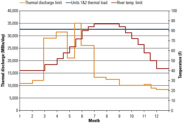 |
| 3. Heat-limited plant. Owners of a four-unit, approximately 600-MW plant using once-through cooling were evaluating the potential requirement to reduce both the plant’s cooling water discharge temperature and thermal discharge limit to a river, in million Btu/day. Shown in orange is the proposed maximum allowable thermal load to be applied to all four units. Shown in dark blue is the typical thermal load from only Units 1 and 2 at full power. Note how the thermal load from only two units exceeds the proposed limit during the entire year, except for part of May. Also included is the anticipated downstream river temperature limitation for the station. Plant operation has resulted in downstream river temperatures up to 120F in the past. Source: Sargent & Lundy |
Our first study of this plant’s cooling water system options assumed that a river discharge temperature limit and a thermal discharge limit were to be imposed on the plant. The worst-case thermal discharge limit was identified to evaluate future operation of the units. As can be seen in Figure 3, the only option without installation of helper cooling capacity was to maximize power generation (in this case, from only Units 1 and 2) up to the thermal discharge limitation (Table 1). Operation of other combinations of units is also possible.
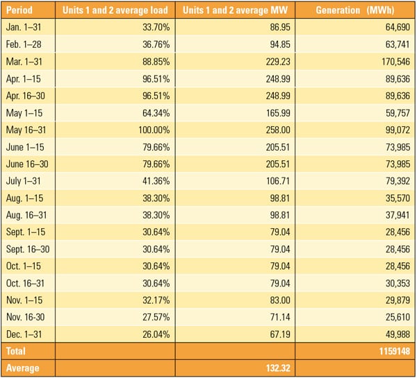 |
| Table 1. Thermally limited operation. By limiting the thermal energy rejection to a river, and without any source of helper cooling, this plant would be forced to limit power generation by shutting down two of its four units and limiting operation during eight months. Many other operating scenarios are possible with the four units. Source: Sargent & Lundy |
A second (separate) engineering evaluation was subsequently conducted based on a different set of proposed limits of river water temperatures. We examined historic plant operating data as a means to develop a mathematical relationship that would allow us to predict maximum allowable generation based on river flow rate, upstream river temperature, and permitted downstream river temperature. With these empirical relationships determined, the theoretical maximum generation was calculated (Table 2) assuming a maximum cooling water exit temperature of 109F or 120F while meeting the maximum downstream river temperatures shown in Figure 3 (Table 2). Downstream river water temperatures were not evaluated for the months of January through April, November, and December due to the minimal predicted generation losses during these months.
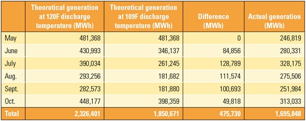 |
| Table 2. Temperature-limited operation. Downstream maximum river water temperature limits will also require units to operate at part-load for about half the year but with no operating limits anticipated during the remainder of the year. The amount of power generated is a function of the average downstream river water temperature selected and the combination of units selected to operate. Source: Sargent & Lundy |
Reducing plant load to decrease downstream river water temperatures is the least capital-intensive but perhaps the most uneconomic option. However, there are other technical options that allow the plant to operate unfettered by river water temperatures that may have much improved overall economics.
The obvious option is converting the once-through cooling water system to a closed cooling water system using one of the many cooling tower technology options. Other less-obvious options are bypass of cold river water around the plant, mechanical chilling of the discharge stream, spray modules in the river, and smaller, “helper” cooling tower cells or modules.
In this particular analysis, the economics leaned toward a closed-cycle cooling conversion. However, an analysis using a helper cooling tower (a tower that operates in parallel with the once-through cooling system when required to maintain the required river water temperature) showed economic promise (Figure 4). A plant derate analysis was performed to determine the optimum number of cooling tower cells required to produce a 109F and a 120F river water temperature downstream of station discharge. When the discharge requirement is 109F, adding more than eight cooling tower cells (modules) provided negligible economic benefit.
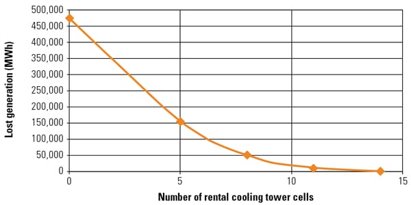 |
| 4. Lend a helping hand. A “helper” cooling tower with perhaps eight cells was found to be the best economic option for the case study plant if it must operate under a downstream river water temperature limitation of 120F. Source: Sargent & Lundy |
Not surprising, the site layout did not consider the future possibility of adding a large cooling tower. Existing infrastructure was carefully considered to properly locate the new cooling tower as well as to minimize installed and operating costs. Options for converting all four units, as well as only two of the units, were also investigated. The ultimate recommended tower location was different than that suggested by other consultants due to the potential for icing of the switchyard. The new location benefited from the ability to reuse existing cooling water piping, although it was directly adjacent to a busy haul road and the coal pile.
After detailed discussions with tower vendors, it was determined that as long as a low clog-type tower fill was selected, the amount of sludge to be removed during basin cleanings would increase, but the dusty location would not otherwise affect tower performance. Furthermore, plume abatement was required due to the proximity of the tower to a nearby bridge, which could experience dangerous fogging and icing from a tower plume.
The proper design point for the plume abatement system was selected and the corresponding additional cost was included in the project budget. The customer now has a solid plan ready to implement should regulators add new river water thermal discharge and/or temperature limits to the plant’s NPDES permit in the future.
— Jeffrey S. Mallory, PE (jeffrey.s.mallory@sargentlundy.com) is a project engineer I for Sargent & Lundy.