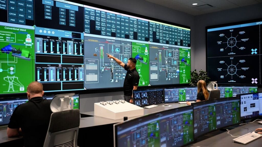
A new advance in vibration monitoring, developed with EPRI, facilitates the measurement of torsional vibration and is expected to be of significant value to power plants relying on a wide range of generating equipment.
The Electric Power Research Institute (EPRI), in conjunction with Suprock Technologies, has conducted a research project to develop and demonstrate an advanced wireless sensor technology for monitoring torque fluctuations in the shafts of turbine generators. The initial sensor design measured shaft surface strain as a basis for assessing torsional vibration amplitude and frequencies. The current sensor design adds shaft surface acceleration measurements.
Currently available proximity probes used as shaft vibration sensors at bearings cannot measure torque. The new sensor will assist plant operators by monitoring torque pulsations caused by grid interactions to ensure they do not produce shaft component vibration and fatigue.
To date, a hardware embodiment of the design has been fabricated and lab-tested. Prototypes were installed and tested on two commercial generating units. No reliability issues were observed with the EPRI hardware during 11 unit-months of sensor operation. These field installations demonstrated the feasibility of the process for securing the instrumentation to the shaft as well as the suitability of the stationary telemetry hardware suitable for use in a plant environment.
Torsional Shaft Vibration
The shaft systems on large grid-connected steam turbine generators can be subjected to dynamic torque oscillations caused by negative sequence currents in the generator. These currents can be grid-induced or caused by unbalanced electrical shorts in the windings.
The resulting torsional stimulus is applied to the generator rotor at twice the line frequency and can result in vibratory response of the entire turbine generator shaft train. Although the torsional stimulus amplitude is very low compared to the static torque produced by the turbine, the resulting torsional response of the shaft system can be amplified if this stimulus frequency is aligned too closely with a natural frequency of the lightly damped shaft system. If undetected, the resulting torsional vibration can lead to accumulation of high cycle fatigue damage in highly stressed rotor elements, such as turbine blades, couplings, exciter shafts, and retaining rings.
The design strategy for reducing the risk of torsional-induced component failures is to ensure that torsional natural frequencies of the shaft systems are sufficiently detuned from the induced stimulus occurring at specific harmonics of the shaft speed. Proper detuning can be verified by measuring the torsional natural frequencies from the operating steam turbine generator. One method for identifying the torsional natural frequencies is to use a wireless telemetry system to measure and analyze dynamic strain and acceleration on the shaft.
Conventional wireless strain gauge telemetry often involves use of custom-fit shaft collars or temporary belts, induced power systems, and a stationary ring-antenna surrounding an exposed portion of the shaft. The custom-fit collars require a unit outage to accurately measure the shaft diameter, followed by a collar procurement lead time. Furthermore, these systems, once installed, are often used for torsional testing over limited time durations, typically a few days—not for long-term monitoring applications.
So, although strain or acceleration measurements may be a technically sound approach for monitoring shaft torsional vibration, the practical difficulties in cost-effective deployment of this technology in a commercial power plant environment have limited its widespread use.
Model Predictions Versus Unit-Specific Measurements
Another issue related to torsional vibration involves upgrades to existing turbine generator sets.
These upgrades commonly include the replacement of entire elements such as low-pressure turbine rotors, generator rotors, or exciters. The new elements introduce changes to the distribution of torsional stiffness and inertia, which result in small changes to the natural frequencies and mode shapes of the entire shaft system. These frequency changes could move the shaft closer to a resonant condition with the generator rotor excitation stimulus at twice line frequency.
The effect of changes in natural frequencies should be evaluated in the design analysis phase of the upgrade project using rotordynamic models. Uncertainty in the model prediction, however, requires the imposition of a wide frequency “avoidance” band surrounding the twice-line-frequency excitation. ISO Standard number 22266-1:2009 provides shaft torsional vibration frequency avoidance criteria. These criteria form the basis for loss control standards by plant insurers such as Nuclear Electric Insurance Ltd. (NEIL). The standards provide an incentive for plant operators to measure unit-specific torsional frequencies rather than to rely only on model predictions. Unit-specific measurements eliminate the model uncertainty, permitting turbine generator operation in a narrower frequency avoidance window.
Need for New Monitoring Technology
As a result, the power generation industry needs a cost-effective and reliable technology for measurement of shaft natural frequencies on operating units. The ideal technology should be installed and used with minimal impact on plant operations and be sufficiently rugged to survive long-term monitoring duty.
In its research project, EPRI worked with Suprock Technologies to first assess currently available commercial strain-gauge telemetry hardware to identify areas for improvement. These areas included type of strain sensor, size and mass of sensor electronics, power consumption, power delivery systems, strain data telemetry, and sensor attachment methods.
EPRI also established a number of design objectives for the new sensor. The design would improve sensitivity to resolve low levels of torsional vibration associated with modes having low elastic energy at measurement locations. The sensor would have a low “noise floor,” which would allow capture of low-amplitude mode frequency indications that can be hidden by traditional wireless instrumentation. A high measurement sampling rate would ensure sufficient frequency resolution to verify that natural frequencies are fully outside the avoidance band at normal running conditions. In addition, the design would not require custom-fitted components, and it would take advantage of available low-cost microelectronics.
EPRI Wireless Shaft Vibration Monitoring System
Based on its analysis of current sensor hardware, and with its objectives for improvement, EPRI developed a wireless telemetry system to meet the needs of the power generation industry.
According to Chris Suprock, principal engineer at Suprock Technologies, “We leveraged advances in sensor technology, digital microelectronics, and radio frequency (RF) engineering. The design is built to withstand the environmental conditions while providing maintenance-free operation. The torsional telemetry system represents a leap forward from previous rotor sensing technologies. Furthermore, the rotor installation process provides a time savings and mechanical improvement over traditional techniques.”
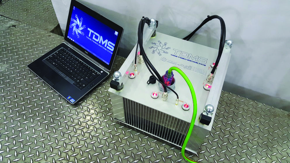
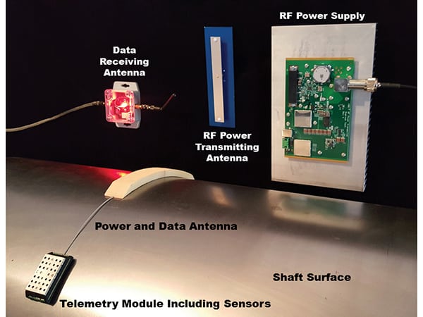
The major subsystems of the torsional vibration monitoring system include: rotating telemetry transceivers, stationary telemetry modules, and a hub computer assembly (Figure 1).
 |
|
1. Shaft torsional telemetry system components. Courtesy: EPRI |
Rotating Telemetry Transceivers
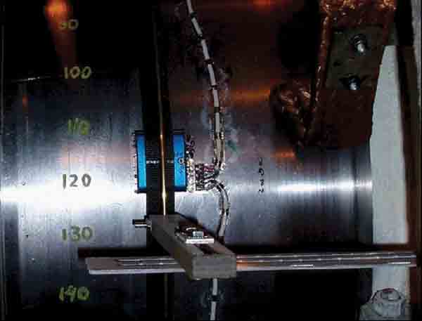
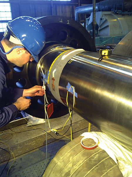
In the current sensor design, a wireless, battery-free, rotating transceiver measures and digitally transmits strain and acceleration data obtained from the shaft surface (Figure 2). The concept is developed from the need for a very compact package with much lower mass and power consumption than conventional telemetry. By reducing the rotating telemetry transceiver mass and size, the need for a custom-fitted shaft collar or temporary belt is eliminated. Developing a standard size rotating telemetry transceiver is an important consideration, so that it may be applied on various shaft diameters without costly customization.
 |
|
2. Prototype. The telemetry receiver components are positioned on a lightly abraded shaft section prior to epoxy encapsulation. Courtesy: EPRI |
The transceivers contain a pair of semiconductor strain gauges and a pair of accelerometers, which are configured to simultaneously measure shaft torsional vibration and lateral vibration. This configuration improves mode frequency detection regardless of the mode shape at the selected transceiver location on the shaft.
The transceiver board transmits a 2.4 GHz signal that contains the strain and acceleration digital data stream. This is received and demodulated by the stationary receiver. The resulting data is archived on the system computer.
An epoxy-infused Kevlar band, or partial band, attaches the rotating sensor board to the shaft surface. The band adheres the sensor to the shaft in a manner that can accommodate expected temperatures and g-loading due to rotation. The encapsulation also protects the sensor board from environmental and mechanical damage in a power plant environment. Key to the design of the sensor attachment and encapsulation system is the ability to perform the encapsulation rapidly, within critical path outage schedules. Equally important is the long-term reliability of the Kevlar infusion and the bond to the shaft. A special vacuum impregnation process has been developed to ensure an aerospace-quality epoxy bond produced within a time-constrained installation window.
Stationary Telemetry Modules
A set of stationary telemetry modules supplies radio excitation and enables control communication with the rotating telemetry transceivers. The stationary telemetry module is attached to adjacent turbine or generator housings within approximately 1 meter of the transceiver location on the shaft. Depending on the shaft size and speed, anywhere from one to three redundant transmitter/antenna assemblies are positioned around the shaft. These power supplies are controlled by the hub computer that sets the data acquisition parameters and stores time-stamped raw data.
Hub Computer Assembly. Each of the several stationary telemetry modules communicates digitally with a hub computer through USB. Software on the hub computer manages the received data, RF power, rotating telemetry transceivers, and stationary telemetry module redundancy. The hub computer is responsible for data logging, configuring of the system, and post-processing the data that has been received from the rotating telemetry transceivers through the stationary telemetry modules.
Data Received from Sensor. The archived telemetry data can be analyzed using one of several data visualization methods:
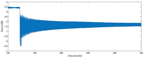
■ Time-transient plots: These plots show strain versus time for a selected strain gauge or accelerometer. This is typically used to capture a brief event associated with a unit trip, grid disturbance, or synchronization (Figure 3).
 |
|
3. Example time transient of shaft strain following unit trip. Courtesy: EPRI |
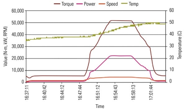
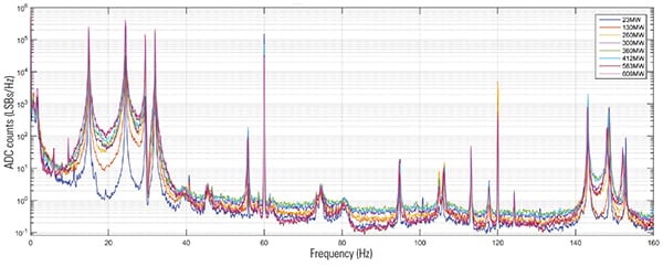
■ Averaged spectral plots: These plots are used to accurately establish the natural frequencies of the shaft system, indicated by peaks in amplitude versus frequency plots. Spectral plots document the variation in shaft natural frequencies with operational parameters such as unit load (Figure 4).
 |
|
4. Spectral plots of shaft strain obtained from generator input shaft at eight unit load points. Courtesy: EPRI |
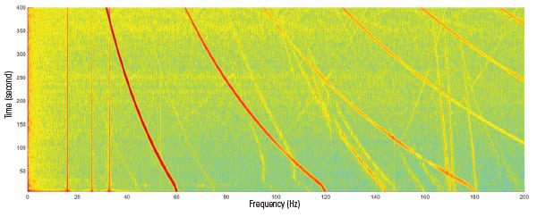
■ Spectrograms: Spectrograms consist of a stacked series of spectral plots obtained during non-steady machine operation—for example, a rotor speed ramp following unit trip. This data visualization format is similar to a Campbell diagram when used to detect trends in turbine blade frequencies with speed (Figure 5).
 |
|
5. Example shaft strain spectrogram obtained following a unit trip. Note the trends in both shaft speed harmonics as well as the natural frequency indications as the shaft speed declines from bottom to top of plot. Courtesy: EPRI |
Field Experience
To date, prototype EPRI torsional sensors have been installed on three shaft locations on two separate generating units. The accumulated operating time represents a total of 11 unit-months of operation without failure of the shaft sensors, circuit boards, or the stationary antenna assemblies.
The data received from the prototype sensor is considered high quality and sufficient to meet the industry needs relative to shaft frequency identification.
A Salt River Project (SRP) Navajo Generating Station (NGS) spokesperson explained that the EPRI equipment was installed toward the end of the Unit 3 major overhaul in the spring of 2015. “The equipment was set up to monitor turbine roll-up of Unit 3 after LP Turbine L-0 bucket upgrades, with hold points occurring at speed no load and different loads up to full load. Data was taken alongside GE’s Life Extension Services program. Both sets of data were used to identify the torsional frequency and mode shapes of the shaft system and components. The results of this data verified that we were running close to the second harmonic of line frequency, which in our case is 120 Hz. Several members of the SRP team—including Israel Perez (turbine engineer), Jim Colsen (mechanical engineer), and Joe Frazier (engineering manager)—along with GE subject matter experts, met to alleviate the issue. The solution that emerged from several meetings resulted in mass reduction along the shaft.”
“In conclusion,” the spokesperson added, “NGS was able to deviate from the second line frequency and run Unit 3 without issue, and this was supported with data that was taken by both systems. To this day, data can be taken and monitored with the EPRI equipment on Unit 3.”
Jim Pratt, senior director of SRP’s Base Load Generation, said it’s important for utilities like SRP to host field tests like this one. “The results of these field tests have the potential to benefit the entire industry. This is one way where EPRI is bringing new technology to the market that directly supports our long-term goals of reliable operation,” Pratt said. “Because of research partnerships like this, we are hopeful to bring products like this to market when we need them.”
The sensor has also been installed for a similar period at Duke Energy’s Marshall Steam Station, and torsional data has been collected over the load ranges and various speeds. A Duke spokesperson notes that, “compared with earlier technologies, the system is very sensitive and provides more data, with a higher degree of granularity, which makes it easier to tell where the torsional peaks are. The data gives us a very good picture of each individual torsional node, so we can identify whether it’s a blade stress or predominantly a rotor-induced torsional stress. That, in turn, helps us identify what the failure mechanism would be and how close we are to that natural frequency.”
Field testing of the prototype system also provided a valuable basis for assessing performance of the following key aspects of the EPRI torsional sensor system:
■ Suitability of the RF excitation to meet the sensor needs, including the specific transmitter/antenna components, antennal layout, and power levels used for both power transmission and reception.
■ Strength and integrity of the Kevlar-epoxy infusion used to attach and protect the sensor system on the shaft.
■ Low noise-floor of the strain spectra, enabling detection of modes with low elastic energy at the sensor location.
■ Demonstration that rotor access time durations required for sensor installation are compatible with typical time-constrained outage plans.
■ Functionality and durability of the entire telemetry system in an enclosed oil-mist environment.
■ Durability of the rotating and stationary telemetry components exposed to high ambient temperatures with seismic vibration.
Future Work
Enhancements to the prototype sensor have been incorporated into an upgraded sensor design. Once this design is field-tested, the system will be commercialized. The goal is to ensure availability of this technology on a wide basis to meet industry needs. It is anticipated that highly sensitive and low-noise shaft strain monitoring will be the basis for advances in a range of new condition monitoring applications on a wide array of power-generating equipment. ■
—Steve Hesler (shesler@epri.com) is the manager of EPRI’s Steam Turbine-Generators and Auxiliary Systems Program.