The consideration of power supplies has become critical to the success of converting analog instrumentation and control systems to digital control systems (DCSs). Careful planning is particularly necessary for nuclear power plants, where instrumentation systems are required for safely shutting down a reactor, mitigating the consequences of an accident, and performing post-accident analysis.
With the conversion of existing analog instrumentation and control (I&C) systems to digital control systems (DCSs), careful consideration and planning of power supply systems has become critical. This article addresses the most important issues that must be considered in the design, operation, and maintenance of power supply systems for nuclear facilities, specifically: power quality, redundancy and diversity of supply, good planning prior to installation, and maintenance of the equipment over its lifespan.
Pursue Power Quality
Most DCSs are provided with power conditioning; however, the equipment selected to provide power for these systems should meet an established set of minimum requirements for voltage regulation and noise suppression to ensure that the output of the uninterruptible power supply (UPS) meets the manufacturer’s requirements for the DCS.
According to the Electric Power Research Institute’s (EPRI) Report TR-1016731, the most commonly reported causes of failure for nonsafety-related DCSs are electromagnetic interference (EMI)-induced disturbances and power supply transients and failures. Power supply transients can include supply voltage surges or spikes, frequency deviations, and noise induced by harmonic content.
Voltage and Frequency Stability. Results of testing documented in the EPRI Report TR-1001072 reveal that programmable logic controllers (PLCs) are most susceptible to the depth, duration, and likelihood of voltage sags. Disturbances to the power system voltage and frequency can result from lighting, short circuits, and switching of loads such as capacitor banks. All of these disturbances can cause transient voltage surges and spikes.
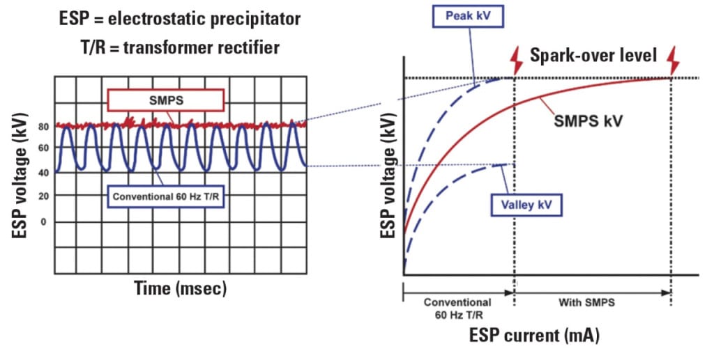
The duration of a voltage sag affects PLC performance and can result in premature system shutdown in some cases. Even momentary voltage surges can result in malfunction of input and output circuits, especially if the PLC power supply is also used to provide sensing voltage for the inputs. For example, a UPS inverter produced a square wave output that was incompatible with three of five PLCs tested. In contrast, a UPS inverter that produced a true sine wave output effectively mitigated voltage sags.
Regulation, Monitoring. The addition of a constant voltage transformer to the PLC’s power supply was found to be very effective in improving the ability of the PLC to ride through such voltage surges and transients. UPS systems that supply equipment that includes a DCS should be designed to produce a true sine wave output to reduce the impact of harmonics.
Battery chargers are not designed to operate as a stand-alone rectifier for an inverter and, therefore, must be always connected in parallel with a set of batteries for the UPS inverter to properly compensate for any transients.
Electromagnetic Interference. EMI and power surges can affect the performance of safety-related equipment in nuclear power plants. This is especially true for DCSs, where noise from EMI can be misinterpreted as legitimate logic signals. The U.S. Nuclear Regulatory Commission’s Regulatory Guide (RG) 1.180 addresses this issue. DCS equipment must be tested in accordance with the standards recommended in this guideline. UPS equipment should meet the minimum standards for radiated and conducted emissions to ensure electromagnetic compatibility with the control systems to which they supply power.
EPRI TR-102323 provides guidelines for data collection, testing, and practices to ensure electromagnetic compatibility in DCSs in nuclear power plants and also to meet the requirements specified in RG 1.180. In addition, surge suppression should be installed on all power and control circuits surrounding these systems to eliminate unwanted disturbances or noise.
Consider Redundancy and Diversity
All DCSs should have more than one power supply, at least one of which will allow for an orderly shutdown in the event of a loss of offsite power. All DCSs should be fed from an AC power source that allows orderly shutdown and data retention during the loss of normal AC power. DCSs that provide redundant design functions should be set up such that failure of a single power supply will not result in multiple failures and/or a loss of more than one system.
The need for UPS-backed power is primarily dependent on the criticality of the control system and the availability of sufficient emergency power until normal AC power can be restored. Control systems with a single AC power feeder should always be powered from a UPS-backed source. Those with multiple redundant power supplies should be powered from at least one UPS-backed AC power source. Consider supplying the UPS for critical control systems from a diesel generator–backed source, especially for those systems needed for safe shutdown and subsequent monitoring following a loss of normal AC power.
Power supplies to multi-train systems should be powered from at least one UPS-backed power supply. Where operation is needed during a loss of normal AC power—such as in shutdown systems, data loggers, and vital computers and alarm systems—consider a second UPS-backed source to maximize reliability and eliminate single-point failure.
In addition, the power feeders to multiple control systems that provide redundant functions should be designed so that the failure of a single feeder does not result in multiple failures and/or a loss of more than one system. Redundant trains or systems should not be powered from the same UPS or normal AC power source such that loss of a single source would result in a loss of both control systems.
Planning Required
Prior to DCS upgrades, planning should address the total amount of power needed and shutdown load requirements needed to ensure reliable operation. The sizing of batteries for the new control system and auxiliary systems should include adequate allowance for future load expansion plus a design margin that includes the effects of temperature and aging. If the addition of the new control system results in low or inadequate margin for expansion, consider replacing the existing UPS system and batteries or install a separate one.
Older UPS systems often have irregular wave forms and high-frequency harmonics that are detrimental to a digital system. The condition and age of existing equipment, especially batteries, will dictate whether or not it is more cost-effective to install a new system or use the existing one.
Finally, think about the space available for installing a new UPS, including separate battery cabinets or racks. This constraint will also affect battery selection, which is discussed later in this article.
Proper UPS Selection
There are two principal UPS configurations. In the single unit float configuration, an inverter is connected to a battery and charger (Figure 1). As long as normal AC power is present, the charger maintains the charge on the battery system and supplies DC power to the inverter, which then supplies the load. This is usually accomplished though a static switch that transfers the load from the inverter to an alternate AC source in the event of a problem with the inverter. The system may or may not be provided with a manual or maintenance bypass switch, which can be used to temporarily feed the load during maintenance activities on the batteries, charger, inverter, or the static switch. One advantage of this configuration is that the battery acts as a buffer to remove excess DC ripple current from the charger, which could otherwise overheat the inverter.
| 1. Two options. In the single unit float configuration, an inverter is connected to a battery and charger. A single unit float configuration may or may not include the single unit maintenance or manual bypass switch. Source: Hurst Technologies Corp. |
The single unit rectifier configuration (Figure 2) is commonly used in both nuclear and fossil-fueled power plants for critical AC systems. Here a separate rectifier supplies power to the inverter. It, in turn, supplies power to the load. Note the addition of a blocking diode between the output of the rectifier and the battery charger output. This prevents the rectifier from attempting to also charge the batteries and any other DC loads that are connected to the same battery or the DC bus. The rectifier for the inverter is specifically designed to supply power to the inverter and is usually rated much smaller than the charger connected to the batteries and the rest of the DC system. The rectifier in this type of UPS is usually designed to supply power to the inverter without being connected to a battery; however, a better input filter is required to eliminate excess ripple as the tank capacity (electrolyte volume) of the battery to smooth out ripple is lost.
| 2. A versatile configuration. A single unit rectifier configuration is commonly used in both nuclear and fossil-fueled plants. Source: Hurst Technologies Corp. |
The type of UPS system used, as opposed to its configuration, depends, among other factors, on power quality requirements and tolerance of the existing power supply system to harmonic currents created by some UPS equipment. The two UPS systems usually considered for plant DCS systems are described here.
Standby Ferro-Resonant UPS. The output of this system is connected to a ferro-resonant transformer with two power connections, one from the transfer switch and one from the inverter. The inverter is normally unloaded, as the normal AC supplies the load via a transfer switch between the power supply and the ferro-resonant transformer. In the event of a loss of normal AC, the transfer switch opens and the inverter supplies the load. The ferro-resonant transformer has additional windings that are connected to capacitors and inductors, which effectively “tune” the transformer and enable it to perform voltage regulation and wave-shaping, including isolation from AC power transients.
Double-Conversion Online UPS. In a double-conversion online UPS, the AC source supplies both the charger and a separate rectifier that supplies DC power to the inverter. The inverter continuously supplies power to the load. If normal AC power is lost, the batteries supply DC to the inverter; hence, no interruption of AC power to the load occurs. This type of UPS system is commonly used for vital AC power to the I&C systems.
Most nuclear plant UPS systems use either a ferro-resonant or a phase-width modulation (PWM) type of inverter. In PWM technology, switching of multiple stages of either SCR bridges or insulated gate bipolar transistors are used to generate a stepped waveform that approximates a sine wave. Output is controlled by varying the repetition rate and width of the pulses in each stage, which also enables the inverter to perform both wave shaping and voltage regulation. At the input to the inverter is either a power factor correction circuit or voltage source converter to boost the input voltage.
This feature also results in lower total harmonic distortion (THD) at the AC input to the rectifier, which, in turn, minimizes the impact on the AC power distribution system. The output of these UPS systems has a lower THD (<4%). They are also more efficient than older systems because they eliminate losses in the ferro-resonant transformer at the output.
Suitable UPS Sizing
Two main factors should be considered in determining load requirements when specifying a UPS: equipment power supplies and control system power supplies.
Equipment Power Supplies. The maximum ratings of the power supplies for processors, modules, and interface hardware should be used in estimating the system power requirements, in addition to AC power required for all workstations, servers, network equipment, and displays requiring UPS power. If applicable, the efficiency ratings of these power supplies should be obtained from the manufacturer’s specifications and accounted for in the estimated load.
Control System Power Supplies. Most DCSs are provided with redundant low-voltage DC power supplies to prevent system failure in the event of the loss of a single power supply. The output of these power supplies is usually connected to an auctioneering circuit (Figure 3). The normal and backup AC power feeders should each be designed to carry the full load of a single power supply.
| 3. Providing power backup. An auctioneering circuit is typical for redundant low-voltage DC power suppliers. Source: Hurst Technologies Corp. |
Best Battery Selection
The term “battery” in this context refers to a bank or rack of battery cells connected in series. In some systems, the cells may also be connected in parallel to provide the required amperage. The type of batteries used in any UPS system depends on the application, power requirements, ambient environment (especially the temperature), and the desired level of maintenance.
Three basic types of battery systems are vented lead-acid stationary batteries, valve-regulated lead acid (VRLA) batteries, and nickel cadmium batteries. In general, the following issues should be considered.
Space. VRLA batteries have fewer limitations on cell orientation, which allows them to be stacked and used in areas that are not equipped with features to control electrolyte spillage.
Ventilation. Both conventional vented lead acid batteries and absorbed glass mat VRLA batteries should be installed in locations with adequate ventilation to avoid buildup of hydrogen in an enclosed area.
Temperature Sensitivity. The capacity of both vented lead-acid battery cells and VRLA cells decreases with temperature. VRLA batteries are much less tolerant of the effects of temperature than vented lead acid batteries. Although both exhibit a loss of capacity as temperature decreases, VRLA batteries also exhibit a loss of life as temperature increases. VRLA batteries are also less tolerant of overcharge, float voltage variation, and discharge than vented lead acid battery cells. Therefore, the cells of these batteries should be installed in a temperature-controlled environment.
Cost. Nickel-cadmium batteries are less temperature sensitive, have a reputation for long life, and pose fewer problems. Nonetheless, cost usually precludes their use in power plants.
Maintenance. Vented lead-acid batteries require regular monitoring of electrolyte levels and cell conditions. Likewise, VRLA batteries should be checked for evidence of swelling or damage. In addition, both types of batteries should be monitored for control of hydrogen concentration.
Minimum backup time requirements for the UPS system should be determined by the minimum time the system is required to operate during a loss of power, safe shutdown requirements, and requirements for monitoring of system parameters, alarms, and data storage. An allowance for diesel-backed power may be made as well; however, some systems critical for safe shutdown may be required to function even upon the failure of the diesel generator–backed power until normal power is restored. A typical backup time for these systems is four hours; however, critical systems may require a minimum backup time of eight hours or more.
— Paul E. Stanley, PE (pauls@hursttech.com); Darrell W. Cooksey, PE (darrellc@hursttech.com); and Tom H. Crawford III, PE (tomc@hursttech.com) work for Hurst Technologies Corp.