A low-frequency, three-phase electrostatic precipitator (ESP) power supply was developed to overcome the many reliability problems with the designs in common use today. Field test results were conducted to confirm its increased reliability and efficiency.
The particulate matter (PM) requirements of the Mercury and Air Toxics Standards (MATS) require filterable PM emissions less than 0.03 lb/MMBtu, which will demand greater particulate removal efficiency from many power plants. MATS also requires increased reliability of particulate removal devices, such as the electrostatic precipitator (ESP).
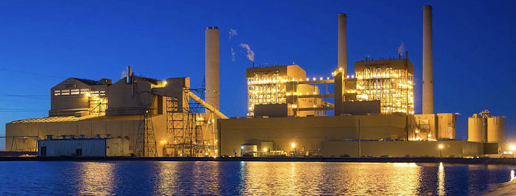
The most common way to improve the performance of an ESP, wherever it is located (Figure 1), is to boost its corona power. The relationship between specific corona power (watts/1,000 acfm of gas flow) and collection efficiency is well understood and is a common upgrade. Other ESP efficiency improvements are possible, such as reconfiguring compartment geometry, increasing plate area, or adding additional fields, although each upgrade usually requires replacing or upgrading existing power supplies. The best option is to select a power supply that can efficiently boost corona power output and maintain high operating reliability. This article describes the development process and testing of a low-frequency, three-phase power supply that may allow operators to upgrade their ESPs to meet the increased particulate removal efficiency required by MATS.
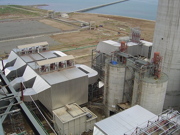 |
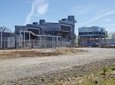
| 1. Performance matters. At this southeast Asia plant, a dry electrostatic precipitator (ESP) is installed on a 660-MW boiler. Globally, the most common way to improve ESP performance is to boost corona power. Source: Babcock and Wilcox Power Generation Group Inc. |
History Lesson
Single-phase power supplies have been a power industry norm for ESPs for more than 60 years. Analog automatic voltage control and silicon-controlled rectifiers were the single-phase design standard for years, although many systems now use microprocessors running proprietary control algorithms to provide more precise control of the power applied to the ESP. However, the single-phase power supply still produces a voltage waveform that contains a significant amount of ripple. Ripple is residual variation from the desired smooth waveform when converting from alternating to direct current in the power supply.
The amount of ripple produced by the power supply determines the amount of power that can be supplied to the ESP. There is a practical limit to how much voltage can be applied to an ESP field due to sparking, and sparking occurs at the peak of the secondary voltage waveform. The practical result is the average voltage produced by the power supply usable by the ESP is always lower than the peak voltage, usually by about 20%. Reducing the undesirable ripple allows the average voltage to be closer to the peak voltage, which allows more power to be applied to the ESP fields, thus increasing particulate removal. Many novel approaches to reduce ripple have been tried by manufacturers, including placing a filter on the output of the single-phase power supply, but with limited success.
Other low-ripple power supply options are available today. Each removes the ripple from the secondary voltage waveform and provides a low peak-to-average-voltage ratio. One relatively new option is the high-frequency switch mode power supply (SMPS) that was designed to provide increased power to the ESP field with better reliability. In actual practice, however, reliability has been less than with the standard single-phase power supply design. In addition, there have been grounding and shielding issues coupled with high input and output harmonic distortion. Also, some high-frequency designs have a turndown limitation (typically 10%), which has been problematic for units that experience large load swings or that cycle often.
Best Alternative Designs
The single-phase power supply design has limited upgrade potential to meet MATS, so Babcock & Wilcox (B&W) began the process of identifying better power supply options. The selection process proceeded down a very logical design path to determine the best ESP upgrade technology: computer modeling, followed by laboratory testing, followed by field testing.
B&W conducted a comprehensive study using computer models of alternative power supply designs to identify the best power supply upgrade options available to improve ESP particulate removal performance and system reliability. Without going deeply into the seven design alternatives considered, technically, the superior option was a low-frequency, three-phase power supply design capable of producing low-ripple voltage waveforms, a design that is popular with European utilities. This design also has the advantage of being derived from the low-frequency, single-phase design that has been in use for more than half a century. The increasingly popular high-frequency SMPS also made the final list. The base case used for comparison was the low-frequency single-phase design.
Next, laboratory testing of ESP power supply options was conducted to confirm results of the computer models and identify additional power supply characteristics that would be encountered in actual operation. For laboratory testing, a test ESP was constructed that considered the entire mechanical configuration of the ESP. For example, different discharge electrodes were configured at various plate spacing, and ESP problems such as close clearances and tracking insulators were studied.
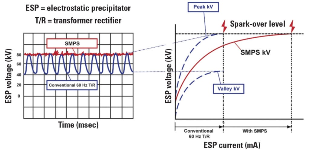
One example of the results of laboratory testing compares the benefits of a low-ripple power supply (Figure 2). In each test, the power supply was operated from zero power to the point where sparking occurred in the ESP, and then a typical average voltage-current (VI) curve was plotted. The selected discharge electrode and the physical configuration of the ESP determined the shape of the VI curve and, as expected, the three power supplies track along the same curve.
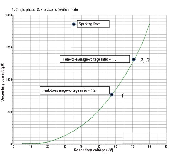 |
| 2. Performance comparison. The VI curve for the single-phase base case and two low-ripple power supplies are compared. The two low-ripple options produce 20% higher voltage, thus producing higher ESP particulate removal rates. Source: Babcock and Wilcox Power Generation Group Inc. |
In all three cases, ESP sparking occurred at 71 kV, which limited the power supply from producing higher voltage. The high ripple on the output voltage of the single-phase power supply (shown as “1” in Figure 1) is clear. The peak voltage was 71 kV with an average 57 kV, which produces a peak-to-average-voltage ratio of about 1.2. For the low ripple three-phase and high-frequency SMPS (points 2 and 3, respectively) also operated with a peak 71 kV voltage and an average 71 kV, the peak-to-average-voltage ratio is ~1.0. A reduction in the peak-to-average-voltage ratio from 1.2 to 1.0 results in a 20% increase in voltage. The net result is up to ~35% more average current and ~50% more corona power available to the ESP, which should result in additional ESP particulate removal efficiency.
More Performance Issues
There are other power supply performance issues that have significant impact on ESP performance, such as spark and quench, harmonics, site application, cost, and reliability. A slate of four power supply sizes (24 kW, 32 kW, 72 kW, and 120 kW) were compared. Commercially available, roof-mounted ESP low-frequency single-phase and high-frequency SMPS power supplies were compared with the low-frequency, three-phase power supply for each of the four design sizes.
Spark and Quench. When a spark occurs, it dissipates all of the energy stored in the ESP field and then the spark is extinguished. In response to the spark, the power supply quenches or turns off for a period of time and then reapplies power to recharge the ESP field.
However, the power supply does not turn off the instant the spark occurs. There is a delay based on the type of power supply, and during this delay, energy continues to be delivered to the spark from the power supply. Each of the power supplies considered delivers less than 0.1% of the total spark energy. The majority of energy (>99.9%) dissipated by the spark comes from the energy stored in the capacitance of the ESP field and not the power supply.
Care should always be exercised with large ESP fields (which increase capacitance) and wide plate spacing (which increases voltage), as spark energy is directly proportional to the capacitance and the square of the voltage.
Total Harmonic Distortion. ESP power supplies connect to the power line and draw power at the fundamental frequency and at harmonic frequencies, which are whole number multiples of the fundamental frequency. This nonlinear load causes distortion of the input waveform and can cause many problems in the electrical distribution system, including heating of conductors, nuisance breaker trips, and interference with other plant equipment. Therefore, it is important to have a measurement of how much distortion exists for each power supply type.
One widely accepted measurement is total harmonic distortion (THD), which is a summation of all of the harmonics present in the system. The modeling results found that the low-frequency design options exhibit the lowest input THD and can therefore be expected to provide significantly fewer installation and maintenance harmonics problems.
ESP power supplies also produce harmonics at the output. The DC waveform is made up of many frequencies, including a fundamental frequency and its harmonics. This is particularly troubling in ESP power supplies because its ground is a current-carrying power lead and is energized with harmonic frequencies. Since all of the plant equipment and the neighboring facility plant equipment are connected through ground, the potential exists to cause interference with other plant equipment, including other ESP power supplies. This is particularly true as radiated radio frequency (RF) emissions increase with frequency. Manufacturers provide detailed bonding and grounding specifications in high-frequency designs, which must be meticulously followed. Low-frequency designs exhibit the lowest output THD and normally experience fewer harmonics problems.
The physical internal electrical connections inside the ESP are also important. Historically, the ESP was constructed for low-frequency operation with bolted or friction fit connections. Both connection types may be inadequate for high-frequency operation, which may lead to voltage drop at the connections, both in the high-voltage distribution system and the ground system. Also, voltage drop in the internal ground connection causes crosstalk and interference between ESP power supplies, which is very difficult to detect, particularly with the connection points located inside the ESP. In general, industry experience is that connection point problems are more difficult to detect and resolve for high-frequency power supplies.
Specific Site Application. High-frequency power supplies are integrated units, unlike low-frequency designs, where the transformer and other components are separate and must be connected together on site. High-frequency power supply designs are also physically smaller and lighter. This can become very important when trying to fit equipment on a crowded ESP roof that has a limited allowable roof load.
However, an integrated unit often means the sensitive electronics are located in a harsh environment and the location makes maintenance more difficult. In addition, high-frequency units require active cooling (air conditioning) of their components, with their additional power demand. Replacement parts are often proprietary.
Low-frequency power supply designs have separate control cabinets and use standard electrical wiring to interconnect. The separate control cabinet allows the high-voltage transformer to be located on the roof while the control electronics can be located remotely, often in an environmentally controlled room located at ground level. This configuration has been successfully used for many years. Also, low-frequency power supply designs are physically larger and heavier, although the power supply can be located off the main ESP structure and then connected by high-voltage cable. Low-frequency systems can use passive cooling for the transformer (air cooling). Lastly, separating the controls and transformer allows each component to be sourced from multiple suppliers.
System Cost. Capital cost is also a significant consideration in the selection process of ESP power supplies, and the differences are significant. For example, if the single-phase power supply cost is 1.0, then the relative cost for a like-sized high-frequency SMPS ranges from 1.49 to 2.31. A like-size low-frequency three-phase power supply’s relative cost is only 1.12 to 1.17.
Also, because the high-frequency power supply designs are fully integrated, there is less field wiring, so installation costs are less than for the low-frequency option. Balancing those installation cost benefits for the SMPS are the increased capital costs for active cooling, environmental protection of the equipment, and higher overall maintenance cost.
System Reliability. The predicted reliability of a power supply is difficult to quantify. The reliability track record of the single-phase ESP power supply is excellent, and many installations have been in service for over 40 years. This is a reliability benchmark that low-ripple power supply designs must match. Anecdotal evidence finds that high-frequency power supplies have experienced a poor reliability record; although it has improved in recent years, it remains lower than for single-phase designs.
Successful Field Testing
The result of laboratory testing was the finding that the low-frequency three-phase power supply option had the greatest potential for improving ESP performance and reliability. The final stage of the development program was to field test the design in order to evaluate its reliability against the familiar single-phase option.
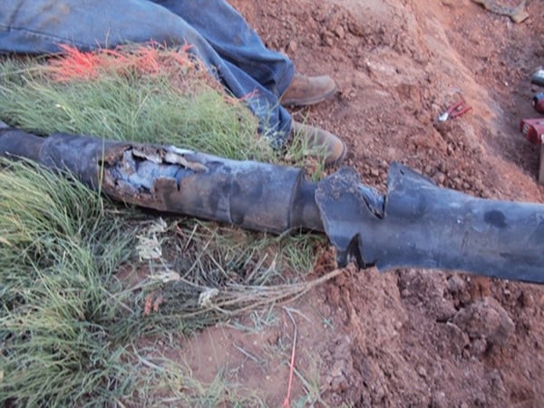
Field-testing of the low-frequency three-phase power supply was conducted on an ESP at an active utility power plant. The unit consists of a tangentially fired boiler burning coal with sulfur content of 1.9 lb/MMBtu with no selective catalytic reduction system or flue gas desulfurization system. The test was conducted during a consecutive six-month period.
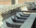
The ESP consists of two boxes with rigid discharge electrodes and 16-inch-wide gas passage. There are four fields (each 12 feet by 50 feet), and eight transformer-rectifier (TR) sets per box (2 x 4 matrices). Fields 1 and 2 have 70 kV, 750 mA conventional TR sets; fields 3 and 4 have 70 kV, 1,000 mA sets. All TR sets are controlled by B&W PGG SQ-300 automatic voltage controls. On the “A” box, the inlet field 1A-1 TR set was replaced with a 480 V, 109 A, 90 kV, 900 mA, three-phase TR set for the purpose of testing. The field test results obtained when operating the test low-frequency, three-phase power supply in a compartment adjacent to a conventional low-frequency single-phase power supply are shown in Figure 3.
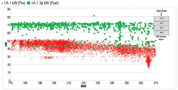 |
| 3. Performance testing. The ESP used as the test bed consists of two boxes, each with four fields and two power supplies per field. The low-frequency, three-phase power supply was tested in one of the ESP fields. The field test showed the three-phase power supply produced an average 50% higher power in the ESP compared to the single-phase precipitator power supply. This suggests that the low-frequency three-phase power supply can produce higher ESP collection efficiencies. Source: Babcock and Wilcox Power Group Inc. |
Field test results confirmed the laboratory test results that the three-phase power supply typically produced 50% more corona power delivered to the ESP than from a conventional power supply (average three-phase power/average single-phase power) with low total harmonic distortion. The installation costs were on par with a standard single-phase power supply. There were no failures of the three-phase power supply during the six-month test run. ■
— David F. Johnston (dfjohnston@babcock.com) is operations manager, precipitator electrical, and John A. Knapik (jaknapik@babcock.com) is senior application engineer for Babcock & Wilcox Power Generation Group Inc. John Walker (John.Walker@duke-energy.com) is electrical engineer for Duke Energy, Wabash River Station. This article is based on a paper presented at the 2014 Power Plant Pollutant Control “MEGA” Symposium.