In March 2007, Datang Huayin Jinzhushan Thermoelectric Power Generation Co., Ltd. placed an order with BWBC for the supply of a 600-MW supercritical steam generator as part of a planned expansion for its power plant located near the city of Leng Shuijiang in Hunan Province of the People’s Republic of China. To efficiently utilize the plant’s low-volatile anthracite coal, a downshot pulverized coal (PC)–fired combustion system was required for the project. This was the first downshot boiler designed to take advantage of the higher plant efficiency of a supercritical pressure steam cycle. Modern supercritical boilers have typically used high mass flux spiral tube furnace designs that are inherently resilient to furnace gas-side heat flux upsets. However, the complex geometry of the lower furnace burner zone makes it very difficult to adapt a spiral tube design to a downshot boiler arrangement.
BWBC is a joint venture company with equal shares owned by Beijing Jingcheng Machinery Electric Holding Co., Ltd. and Babcock & Wilcox Power Generation Group Inc. (B&W PGG). BWBC licenses a full range of B&W PGG utility boiler products and technologies focusing primarily on the China market and is a key partner supporting B&W PGG as a primary detail engineering and fabrication shop for utility and industrial products sold worldwide. When Jinzhushan 3 required supercritical boiler technology for a downshot arrangement, B&W PGG worked closely with BWBC to develop a solution that utilized low mass flux, vertical tube Benson boiler technology originally pioneered by Siemens AG. B&W PGG licenses this technology from Siemens and has further developed it into a commercial product, the B&W PGG VTUP boiler.
The low mass flux technology offers advantages of natural circulation flow characteristics in the furnace tubes, which can help self-compensate for inherent upsets in heat absorption rates in the furnace. The vertical orientation of the tubes in the VTUP boiler furnace panels was also much easier to adapt to the lower furnace arrangement of the downshot boiler. Other advantages include a lower furnace water/steam pressure drop, resulting in significant savings in power consumption of the feedwater pump as well as a simpler mechanical support system for the furnace and less complexity for shop and field construction and fit-up.
In July 2009, Jinzhushan Unit 3 successfully completed its 168-hour test run and in September 2009 passed its performance test, proving the successful application of the world’s first supercritical, PC-fired low mass flux vertical tube boiler. This successful demonstration establishes B&W PGG’s VTUP low mass flux supercritical boiler technology as a viable alternative supercritical steam generation technology for the electric utility generation industry, whether for a downshot or wall-fired pulverized coal application.
Jinzhushan 3 Boiler Description
The Jinzhushan 3 boiler is designed to supply main steam to a 660-MW supercritical steam turbine generator set at a rate of 1,900 tons/hr (4,189.5 klb/h) at 3,683 psi (25.4 MPa) and 1,060F (571C) with reheated steam at 1,056F (569C). A heater above reheat point steam cycle is used, providing feedwater to the boiler at 552F.
The B&W VTUP downshot boiler arrangement is illustrated in Figure 1. The unit is a two-pass once-through supercritical boiler with a vertical tube membrane water wall furnace with a parallel downpass. Reheat steam temperature is controlled by biasing flue gas between the reheater and primary superheater paths in the downpass. Major dimensions are shown in Table 1.
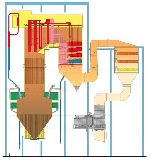
1. Jinzhushan 3 VTUP downshot boiler. Courtesy: B&W PGG
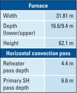
Table 1. Jinzhushan Unit 3 boiler dimensions. Source: B&W PGG
Fuel Analysis
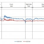
The coal is delivered from a mine near the plant. The design coal is unique, and its characteristics significantly influenced the boiler design. The ash is primarily silica and alumina, which exhibits a very high ash fusion temperature, minimizing slagging concerns. However, because silica and alumina are very erosive in nature and the total content of the ash is very high, gas velocities through the convection heating surface were designed to be very low, approximately 7.5 meters per second.
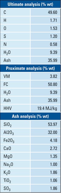
Table 2. Jinzhushan Unit 3 fuel analysis. Source: B&W PGG
Low-volatile anthracite requires a hotter furnace to sustain combustion compared to more common, higher-volatile, lower-rank coals. The downshot furnace with refractory-lined burner zone provides an effective combination of long residence time and high temperature. The burners fire downward into the refractory-lined zone of the furnace. The combustion products then turn upward to leave the burner zone, as shown in Figure 2. As the flame turns up to exit the lower furnace, the char reactions return heat to the ignition area, increasing the effectiveness of the combustion process. The enlarged lower furnace also provides extended residence time of the fuel particles, allowing the slower-burning char to burn out more completely.
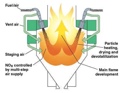
2. The downshot furnace. Source: B&W PGG
B&W PGG and BWBC have designed and supplied many downshot furnaces for subcritical boilers. However, there is a special challenge when designing the downshot furnace for a supercritical application. The spiral furnace geometry traditionally used on variable pressure supercritical boilers is very difficult to adapt to the complex arrangement of the downshot furnace geometry. A vertical tube configuration is needed to adapt to the lower arch or burner shelf of the downshot furnace. To ensure that all the furnace tubes are exposed to nearly even heat distribution through the refractory-covered combustion zone, the corners of the lower furnace are mitered, as shown in Figure 3. Subcritical downshot furnace designs have typically used square corners.
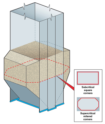
3. Downshot furnace configuration. Source: B&W PGG
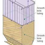
The furnace walls are constructed of vertically oriented membrane tube panels. The lower section of the furnace uses optimized multi-lead ribbed tubes and extends up to a set of transition headers at an elevation approximately midway up the furnace shaft. The transition headers interconnect through mixing bottles, which equalize the enthalpy entering the upper furnace panels. The upper furnace panels use smooth tubing. Riser tubes extend from the upper furnace enclosure headers to a manifold header, where the fluid is mixed and routed to two vertical steam separators.
The steam passes from the vertical steam separators through the furnace roof and then to the horizontal convection pass (HCP) enclosure walls and the rear pendant convection pass enclosure panels. The steam from the rear roof header flows down the rear HCP wall and up the HCP side and front walls. The flow is then routed to the upper baffle wall header and down the baffle wall to the primary superheater inlet. The steam then flows through the primary superheater, the platen superheater in the furnace, and finally the secondary superheater. Spraywater attemperators are located at the platen and secondary superheater inlets.
Reheat steam is first heated in the front section of the horizontal convection pass and then passes through the final reheater sections in the pendant convection pass. The reheater is arranged with double-end inlet and outlet steam connections at the headers. Reheat steam temperature is controlled during steady-state conditions by biasing gas between the front and rear parallel gas passes in the horizontal convection pass using dampers located at the boiler outlet. Attemperation at the reheater inlet provides reheat steam temperature control during load transients.
Combustion System
To supply pulverized coal to the burners, the boiler uses a direct firing system that includes 12 gravimetric coal feeders, six ball mill-type pulverizers, and 24 B&W PGG half primary air exchange burners. Twelve burners are arranged on each front and rear wall burner shelf. Combustion air is supplied by two axial flow primary air fans and two axial flow forced draft fans. Two trisector-type air heaters are used to preheat the combustion air. A selective catalytic reduction system with two initially installed layers and space for one future layer of catalyst is located above the air heater. The balance of the flue gas and emissions control system includes an electrostatic precipitator and two axial flow induced draft fans per unit.
Boiler Startup System
A schematic of the boiler water/steam and startup system arrangement is shown in Figure 4. The startup system equipment consists of two steam water separators, a water collection tank, a boiler circulating pump, and the associated piping and control valves to return the fluid from the water collection tank to the economizer inlet.
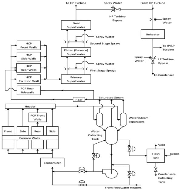
4. Steam/water circuitry and startup system. Courtesy: B&W PGG
During startup, the unit is operated much like a drum boiler, where water is recirculated to maintain a minimum flow through the furnace equivalent to 30% of full load flow. The system is similar to a pumped circulation drum boiler with the steam water separators and the water collection tank functioning like the steam drum. The water flowing through the furnace is a combination of water from the water collection tank and boiler feedwater. The boiler feed pump controls the total flow through the furnace so the minimum required mass flow is maintained.
Steam generated through the furnace circuits is separated from the water in the vertical separator, routed to the superheater, and then to either the steam turbine or the turbine bypass system. The water from the vertical separator is returned to the water collection tank and then to the circulating pump. The 381 valve, located at the discharge of the circulating pump, controls the flow proportionally to tank level to maintain the water inventory in the collection tank. Water is also recirculated from the pump discharge to the collecting tank to ensure that minimum flow required through the pump is maintained.
Above the minimum boiler load (or Benson load) the unit switches to once-through operation. The circulating pump is taken out of service but is kept pressurized. A small flow of feedwater from the economizer outlet is routed to the circulating pump inlet and back to the separator to maintain the components in the ready state for use during shutdown.
Part 2 of this report will examine the design details of this unique boiler. Part 3 will present boiler performance and Jinzhushan Unit 3 performance test results.
—A.J. Bennett, M.J. Albrecht, and C.S. Jones work for Babcock & Wilcox Power Generation Group Inc., Barberton, Ohio. Q. Zhang works for Babcock & Wilcox Beijing Co., Ltd., Beijing, People’s Republic of China. Y. Chen works for Datang Huayin Jinzhushan Thermoelectricity Power Generation Co., Ltd., Hunan Province, People’s Republic of China.