Six times during the previous year the local utility supplying power to a large soap manufacturing plant in the Midwest suffered power outages, shutting down the plant’s production lines. Each time the lines went quiet, product hardened requiring the process to be flushed, cleaned, and reset. Even momentary outages caused downtime that could last hours. Productivity halted, costing time and money. Something had to be done about power reliability at the plant.
Previously, in pursuit of increased efficiency, management had installed an engine-generator in a combined heat and power (CHP) application. This unit provided supplementary electricity and waste heat to the process.
To address the reliability issues, management investigated the possibility of expanding the generator’s role from an electricity supplement to an earnest backup power supply for critical loads. This distributed generation intended to improve efficiency came with a possibility of improving reliability as well, a win-win.
The project came with a catch, however. The maximum output of the generator is 4.4 MW, but the peak plant load is 6.2 MW. How could the plant run on lower power supply without disrupting manufacturing?
Automation in the form of a microgrid control system is one way. This system decouples the plant’s power system from the utility, switches the generator’s control mode to islanded operation, and deenergizes the non-essential loads to ensure the essential loads remain online. All this must occur reliably and within a very tight timeframe, which necessitates careful planning and engineering.
Microgrid Control System Design
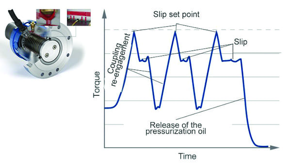
Due to the proliferation of communication networks and microprocessor-based devices in the industrial environment, automation systems have a vast range of capabilities. Microgrid control systems are no different. These systems can perform functions such as automatic grid decoupling and recoupling, load shedding (Figure 1) and adding, power system control during islanded configurations, and many other protection, metering, and diagnostic functions.

In This Issue
Full issue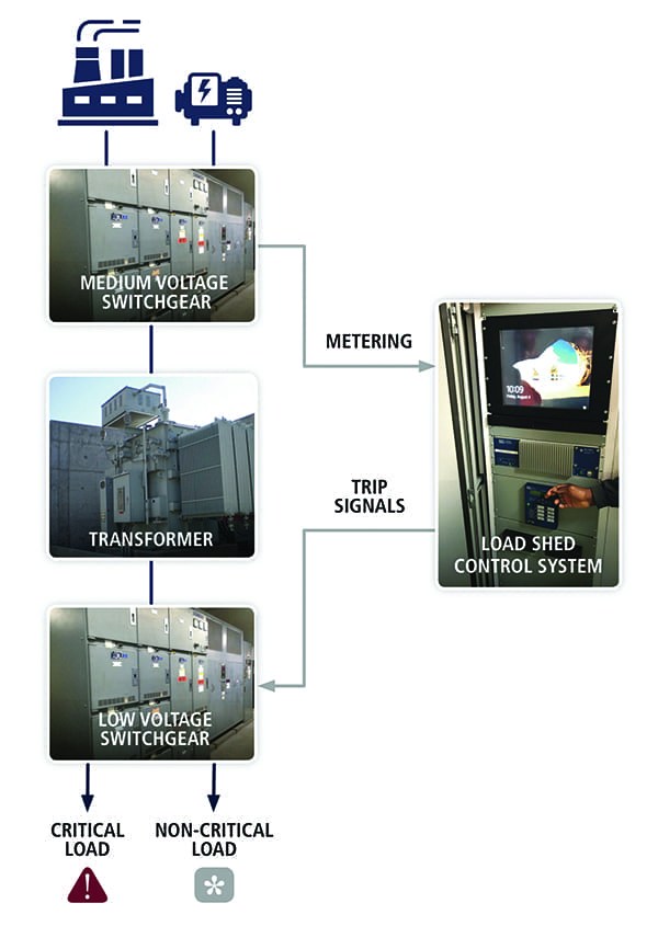 |
|
1. This graphic shows the power and signal flow for a load-shed control scheme. Courtesy: Stanley Consultants |
Commensurate with this range of capability, these systems also come with a wide range of cost. A study was performed to strike an appropriate balance between capital investment and system capability.
First, it was determined that automatic grid decoupling was required. When a disturbance occurs on the utility’s system, the plant must be disconnected in milliseconds to ensure it maintains dynamic stability. The plant must be isolated from the problem before electrical parameters such as voltage and frequency drift outside of acceptable tolerances. Because this must occur so quickly, in practice, this cannot be done via manual intervention—automation is required.
Next, the capacity of the engine-generator was originally selected based on space constraints and economic optimization, not based on total plant load. The chosen capacity of the generator was 4.4 MW, but the plant load was greater than 5 MW more than 60% of the time. Therefore, some form of load shedding was required to automatically disconnect less-critical loads when the plant’s power system was decoupled from the utility. This could be accomplished in the microgrid control system.
The controls had to be programmed to shed non-critical loads immediately, allowing loads critical to the factory’s primary processes to remain operational. Non-critical loads include building support systems, such as HVAC and shop air compressors. Critical loads directly support the manufacturing process. The team studied metering data to determine how often critical load levels were less than the generator’s capacity. It was found that this was always the case.
Automatic load shedding takes many forms. First, one must determine where the loads will be disconnected. This can be done at the medium-voltage level, where disconnecting breakers removes large sections of the distribution system. Alternatively, it can be done at the low-voltage part of the system, allowing for a more discerning system.
In a retrofit application, such as this, the benefit of performing the operations higher up in the system, at the medium-voltage level, is that electrical breaker control is standard. This means that the switching devices can be opened and closed by a remote-control system. The disadvantage of this location is that only coarse control can be achieved. This increases the risk of over- or under-shedding.
Over-Shedding, Under-Shedding Issues and Solutions
Over-shedding occurs when too many loads are disconnected from their power source. At a minimum, this problem disables more equipment in the factory than required. Worse, if the amount of load shed exceeds the load step-change capability of the generator, the entire system can become unstable. This is a greater problem for spark-ignited gas engines than for diesel engines, which can be more tolerant to load step changes.
Under-shedding occurs when not enough load is removed from the system, which will cause the generator to trip due to a number of reasons, including overload or under-speed. These risks can be mitigated by shedding power lower in the system, at the low-voltage level. At that level, the system has finer control. The issue here is that the switching devices may have manual-only control, requiring modification to afford them remote control. Additionally, interconnection wiring and conduit is required to add remote operation. This adds cost.
 |
|
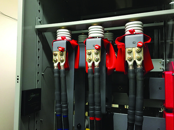
2. This graphic illustrates the magnitude of non-critical and critical load versus generator capacity. Courtesy: Stanley Consultants |
Once it’s determined where the load will be shed (Figure 2), it must be determined how this shedding will take place. There is a wide range of sophistication that can be implemented. In the most advanced cases, the control system can continuously monitor load levels on individual loads and sources. Some systems can even continuously update an estimated system inertia value.
Advanced systems can execute predictive contingency-based algorithms that use data to continuously update the list of actions that the system will perform in the event of a disturbance. The less advanced systems retroactively shed predefined loads.
One Solution
In the case of this factory, the following solution was implemented. To determine how much load needed to be shed, the control system continually metered the power flowing into the facility and out of the generator. This was done with communication connections to the main breaker and generator breaker’s protective relaying. The difference between these two values was the target amount of load to be shed in the case of a decoupling.
In the interest of balancing cost and load-shed accuracy, individual low-voltage switchgear feeder breakers were used for the load-shed location. Some of these breakers already had remote control capability; where they didn’t, the breakers were retrofitted with shunt-trip devices.
Next, individual loads did not have devices capable of providing metering information to the network. Instead of adding this capability, which would increase cost, typical load values for each feeder capable of shedding were hard-coded into the system. Also, these loads were assigned priority levels that told the system which loads were most critical.
Finally, the system was programmed with a curve that told it how much of a step change the generator could tolerate under varying output levels. All this information was used in a contingency scheme that decided which loads would be quickly shed if the protective relaying decoupled the plant from the grid.
Once the control system placed the plant into an islanded configuration, it communicated with the engine control system to switch the generation mode to one appropriate for the islanding situation. Again, to minimize capital cost, the owner chose to return to the utility-connected state manually, rather than automating this function.
With careful planning and engineering, this facility was able to leverage existing assets to increase reliability, executing only modest capital investment. As distributed generation becomes more prolific, so does the opportunity to magnify installed equipment utility via modern controls.
—Joe Thornam is a principal electrical engineer with Stanley Consultants Inc. in Denver, Colorado.