As early as the first century A.D., wind energy was harnessed for practical purposes. Since then, turbine designs have come a long way from the archetypal post-mounted four-bladed devices. Today’s ubiquitous three-bladed designs will soon be evolving in many unexpected directions.
The first wind turbine used to convert wind energy into power—unlike windmills, which are used to pump water or grind grain—was built by Professor James Blyth of Anderson’s College, Glasgow (now Strathclyde University) in 1887. Blyth’s experiments with three different turbine designs resulted in a 10-meter-high (33-foot-high), cloth-sailed wind turbine, which was installed in the garden of his holiday cottage at Marykirk in Kincardineshire. It is said to have operated for 25 years.
Blyth’s invention marked the dawn of wind turbine development. Close on its heels was a turbine built by American inventor Charles Brush in 1888. That 12-kW turbine featured 144 blades made of cedar, each with a rotating diameter of 17 meters (Figure 1).
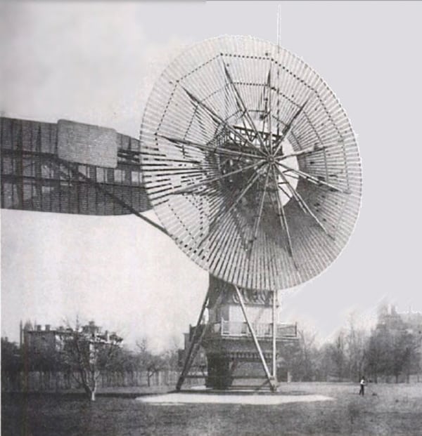 |
| 1. The Brush. American inventor Charles Brush in 1888 built one of the first wind power turbines. Source: Wikimedia Commons |
Then came the work of Danish scientist Poul la Cour in the 1890s, which spawned about 2,500 turbines in Denmark by 1900, with an estimated combined peak power capacity of 30 MW. La Cour’s wind turbines produced hydrogen as well as power.
Wind-powered turbines were installed by the millions around the world thereafter, particularly in the American Midwest, where they were used to power irrigation pumps. By 1931 the first forerunner of the modern horizontal-axis wind generators was put into service at Yalta, in Russia. It was a 100-kW generator on a 30-meter-high tower that featured a load factor of 32%. And in 1941 the world’s first 1.25-MW turbine was grid-connected on Grandpa’s Knob in Castleton, Vt.
The first modern wind turbine was built in Denmark around the mid-1950s. According to the Danish Wind Industry Association (DWIA), the 200-kW Gedser wind turbine (Figure 2) was built in 1956 by engineer Johannes Juul for electricity company SEAS on the Gedser coast in southern Denmark. The concept—a three-bladed upwind turbine with electromechanical yawing and asynchronous generator—was a “pioneering design for modern wind turbines, although its rotor with guy wires looks a bit old fashioned today,” says the organization. The turbine was stall-controlled; Juul invented the emergency aerodynamic tip brakes, which were released by the centrifugal force in case of overspeed. “Basically, the same system is used today on modern stall-controlled turbines,” the organization says, noting that Juul’s turbine ran for 11 years “without maintenance.”
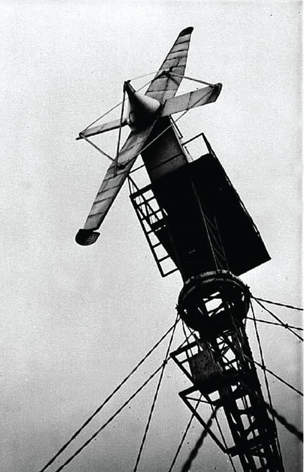 |
| 2. The Gedser. The first modern wind turbine made its appearance in the mid-1950s and was built by Danish engineer Johannes Juul. Courtesy: Danish Wind Industry Association |
Wind power caught new wind after the first oil crisis in 1973 as Denmark, Germany, Sweden, the UK, and the U.S., among other countries, scrambled to design larger turbines. In 1979, Danish developers succeeded in building two 630-kW wind turbines, a pitch-controlled and a stall-controlled model. “In many ways they suffered the same fate as their even larger colleagues abroad,” says the DWIA. “The turbines became extremely expensive, and the high energy price subsequently became a key argument against wind energy.”
In addition to the design developments discussed below, which aim to increase efficiency and lower costs, other developments in the energy delivery infrastructure will have an effect on the use of wind power. The development of a smarter grid will enable smoother integration and dispatch of large- and small-scale wind generation (see p. 46, “The Smart Grid and Distributed Generation: Better Together”), and an important component of any grid in the future will be more widely available energy storage (see p. 30, “Energy Storage: Just-in-Time Generation”).
Horizontal- and Vertical-Axis Turbines
Today, most modern wind turbine designs continue to be classified according to the configuration of the rotating axis of their rotor blades. Two categories dominate: horizontal-axis wind turbines (HAWTs) and vertical-axis wind turbines (VAWTs). More than 90% of wind turbines in use today are thought to be of HAWT design. According to Dr. Rigoberto Chincilla, an associate professor of applied engineering and technology at Eastern Illinois University, a primary reason modern HAWTs dominate the market is that the arrangement of their blades allows them to always fully interact with the wind, which critically improves the power coefficient of modern HAWT turbines.
But HAWTs also have several disadvantages, he says. A common one is that they are noisy. Broadband noise, mainly originating from aerodynamic phenomena (like airflow around the blades, hub, and tower), and tonal noise, caused by the vibration of mechanical components, can range in sound pressure levels ranging from 58 dBA (just above ambient noise) to 108 dBA (the sound of a Boeing 707 or DC-8 aircraft at one nautical mile before landing). Another objection is that HAWTs are seen as “eyesores.”
HAWTs are also technically limited in three critical ways. As Chinchilla points out in a January 2011 article published in the Journal of Industrial Technology, as well as being unable to withstand turbulent winds found in urban environments, HAWTs cannot operate in high winds because large turbines must yaw (or turn) their blades out of the wind and apply a brake when wind speeds reach about 55 miles per hour (mph).
Chinchilla and the article’s coauthors, Dr. Sam Guccione and Joseph Tillman, also suggest that HAWT design size is reaching its capacity limit. Though mammoth structures—much larger than the 5-MW HAWTs with 400-foot-long blades currently operating—are in the development pipeline, the end is in sight, they say. “It is doubtful that reliable 10-MW HAWTs will ever be built.”
All these factors contribute to the renewed interest in VAWTs, assert Chinchilla, Guccione, and Tillman, even though VAWTs, too, have many disadvantages—foremost among them that they aren’t as efficient as HAWTs.
On the X-Axis: Unconventional HAWTs
Just too many novel—and sometimes plain wacky—designs are out there, Angelika Pullen, the Global Wind Energy Council’s communication director, told POWER in February. How far the classical HAWT turbine has come is particularly worth noting, she pointed out. “It is taken too much for granted that the ‘classical’ horizontal axis wind turbines on the scale of 5, 6, 7 MW exist, but these machines are really high tech, can almost behave as classical power plants (delivering both energy and grid support services), and are capable [of operating] unmanned for 20 years and more in the most harsh conditions both onshore and offshore,” she said. “They are the largest rotating structures on earth, and the blades are the largest single-piece components ever made on Earth.”
Perhaps the most promising classical HAWT spinoff is the floating wind turbine. In June 2009, Siemens Wind Power towed the 2.3-MW Hywind facility—the world’s first large-scale floating wind turbine—to a North Sea location with a water depth of about 220 meters. (For more on this POWER Top Plant winner, see our December 2009 issue or “Hywind Floating Wind Turbine, North Sea, Norway” in our online archive at https://www.powermag.com.) Several companies have since been scrambling to develop similar technologies, the latest, a consortium that includes Portuguese firm Energias de Portugal (EDP), Seattle-based Principle Power, and Denmark’s Vestas. Those companies in February agreed to deploy a full-scale 2-MW turbine on WindFloat (Figure 3), a floating offshore wind foundation outfitted with a Vestas V80 2-MW wind turbine.
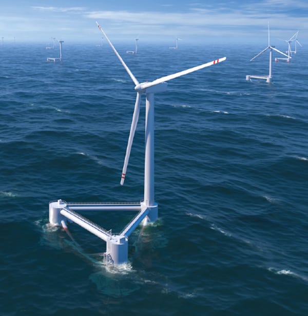 |
| 3. WindFloat. Danish wind turbine maker Vestas in February teamed with U.S.-based Principle Power and Portugal’s EDP to test a 2-MW floating wind turbine off the Portuguese coast, beginning this fall. The WindFloat reportedly decreases wave- and turbine-induced motion and can harness wind energy in waters more than 50 meters deep. Courtesy: Principle Power |
Japanese scientists, meanwhile, are touting another variation—the Wind Lens, a shrouded six-bladed HAWT 112 meters in diameter, which would be arranged in a honeycomb-like pattern (Figure 4). The concept has received much acclaim because it is thought capable of producing four to five times more power than conventional offshore turbines—though its designer, Kyushu University Professor Yuji Ohya, who unveiled the turbine at the Yokohama Renewable Energy International Exhibition in 2010, admitted he was uncertain whether the Wind Lens would ever actually be commercially produced, especially outside Japan.
 |
| 4. The Wind Lens. The shrouded horizontal-axis wind turbine for offshore use was developed by Kyushu University Professor Yuji Ohya in Japan. Courtesy: SCF Committee/ Kyushu University |
Shrouded, or ducted rotor, turbines are more than a century old, but they are being reinvented every 20 years or so mainly because of their power potential. The shroud (or static diffuser) creates a pressure drop behind the rotor blades, causing increased flow through the propeller, even though efficiency is reduced because the airstream breaks up as it passes through the diffuser.
The latest reincarnation of this unconventional HAWT—also called a diffuser augmented wind turbine—is FloDesign Wind Turbine Corp.’s “jet engine” prototype (Figure 5). Integrating aerospace technology known as a mixer ejector, the prototype is much smaller than earlier designs, making it easier to align blades to the direction of the wind, says the firm’s founding CEO, Stanley Kowalski. A number of investors are watching the prototype’s development. The U.S. Department of Energy has jumped in, too, awarding the company $8.3 million through its Advanced Research Projects Agency–Energy in October 2009.
 |
| 5. The jet engine prototype. Massachusetts-based aerospace technology company FloDesign is developing a shrouded turbine that, based on jet engine technology, directs air into patterns to create a rapid-mixing vortex. A fin directs the turbine to face the direction of the wind. Courtesy: FloDesign Wind Turbine Corp. |
On the Y-Axis: The Darrieus and the Savonius
Generally, VAWTs derive from one of two principle designs: the lift-based VAWT patented by Georges Darrieus in 1931, which uses two or three curved or straight blades joined together at the top and bottom and bowed outward in the middle in a troposkein (Figure 6), and the drag-based VAWT, created by Finnish engineer S.J. Savonius in 1922, which uses two S-shaped blades for the rotor.
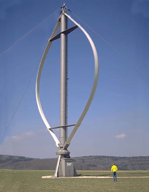 |
| 6. The Darrieus. French engineer Georges Darrieus’ 1931 vertical-axis wind turbine design—shaped like an eggbeater—has resurfaced in modern times. Courtesy: German Wind Energy Association |
Darrieus’ design languished for several years after it was patented until it was revived by the Canadian National Research Council in the early 1970s. Theoretically, the Darrieus VAWT is as efficient as a HAWT if wind speed is constant—but this is rarely the case.
Nevertheless, armed with a €3 million grant from the European Union, researchers from Denmark’s national laboratory for renewable energy, Risø DTU, last October set out with 11 other international partners to launch a four-year-long project to float eggbeater-shaped wind turbines. The project, dubbed “DeepWind,” seeks to develop more cost-effective megawatt-scale wind turbines through “dedicated technology rather than advancing existing concepts that are based on onshore technology being transported to the sea environment,” as Project Manager Uwe Schmidt Paulsen said. The effort would not be without challenges, he admitted, especially because of the long subsea support structure needed. If the project pans out, after a 1-kW demonstration in the open waters of Roskilde Fjord in Denmark, the consortium will design a 5-MW concept; it plans to eventually build a 20-MW turbine.
Another popular variation of the Darrieus design, the H-rotor design or Giromill, is also being tested offshore. Technip—a French firm that worked with Siemens and Statoil to launch the Hywind floating turbines in Norway—in late January launched the Vertiwind project to test a pre-industrial prototype along with French partners Nénuphar, Converteam, and EDF Energies Nouvelles (Figure 7). This turbine replaces the long “eggbeater” blades of the common Darrieus design with two or more straight vertical blade sections attached to the central tower by a horizontal arm. Technip said that the VAWT design was ideal because it freed the turbine of constraints related to foundations of fixed wind turbines, and it doesn’t have a yaw or pitch system, a gearbox, or complex blade geometry. Those features result in lower installation and operation costs.
 |
| 7. Vertiwind. French company Technip and partners Nénuphar and EDF Energies Nouvelles, among others, have launched a project that would test the Darrieus H-rotor design offshore. Courtesy: Nénuphar |
The UK’s Energy Technologies Institute (ETI) also recently blessed the use of VAWTs as a viable alternative to traditional offshore turbines. ETI vouched that they can flourish technically, economically, and environmentally, even when sized as large as the 10-MW VAWT Aerogenerator. The Aerogenerator is half the height of an equivalent HAWT, and its weight is concentrated at the base of the structure (Figure 8). “There are benefits in terms of the design of the turbines and accessibility at sea which could help reduce the cost of energy,” said ETI chief executive David Clarke, though he admitted that the prototype still had a long way to go before an actual demonstration.
 |
| 8. Aerogenerator. British turbine-maker Wind Power is developing a 10-MW floating vertical-axis wind turbine. Courtesy: Wind Power |
The same structural design benefits that make VAWTs ideal for offshore use have allowed development of magnetic levitation technology to thrive. As scholars Huachun Wu, Ziyan Wang, and Yefa Hu from China’s Wuhan University of Technology assert in an April 2010 paper, wind speeds in most urban areas—specifically in China—are much lower than 4 meters per second (m/s). “The mechanical frictional resistance of existing wind turbines is too big,” they say, but this can be remedied with the so-called “maglev” wind turbines, which rely on full-permanent magnets—not electromagnets or ball bearings—to suspend the turbine blades above ground.
The almost-floating vertical blades (Figure 9) spin with little resistance, even in light breezes (as low as 1.5 m/s). That increases power output and device lifetimes, said researchers from Guangzhou Energy Research Institute (which is under China’s Academy of Sciences) and stakeholders Guangzhou Zhongke Hengyuan Energy Science & Technology Co., Ltd. when they introduced the turbine in 2006.
 |
| 9. Maglev. When Chinese developers unveiled the magnetic levitation wind turbine at the 2006 Wind Power Asia Exhibition, it was hailed as a breakthrough in the evolution of wind technology. The technology is today used to power streetlights in Shenzhen and is available in ranges from 300 W to 1 kW. Courtesy: Shenzhen TIMAR Wind-Solar Energy Technology Co., Ltd. |
Theoretically, a large maglev wind turbine could be rated at 1 GW, decrease operational costs by 50%, and last as long as 500 years—though developers note that the large-scale machines required to do so could cost up to $50 million.
VAWTs are gaining ground in the small wind market, too. One example, a Giromill, is Windspire Energy’s 30-foot-tall, 4-foot-wide Windspire (Figure 10), which is said to generate some 2,000 kWh per year at 11 mph annual average winds. The Windspire was part of the National Renewable Energy Laboratory’s (NREL’s) independent testing project, but NREL terminated testing in January 2009, barely a year after the VAWT had been commissioned, because of “turbine component failures.” Windspire says the test model was one of its “earliest production units,” and it has since improved the turbine. Through a grant from NREL, the company plans to test and certify the new turbine according to standards promulgated by the Small Wind Certification Council—an independent body that began to accept performance and safety certification applications from small wind turbine makers just last year.
 |
| 10. Windspire. Nevada-based Windspire’s Giromill generates power when the wind blows against the vertical airfoils, causing them to spin. Courtesy: Windspire |
The second type of VAWT—the Savonius—uses a rotor, formed by cutting a cylinder into two halves along the central plane and then moving the two semi-cylindrical surfaces sideways along the cutting plane so that the cross-section resembles the letter “S.” One much-cited modern-day example of a Savonius turbine is the Helix system from Helix Wind (Figure 11). The company says that as the wind blows (at speeds as low as 10 mph), the long helical blades catch wind from all directions, forcing it through the turbine. The turbine and generator assembly are currently being tested for UL listing, with which the turbine would be eligible for rebates under all state renewable energy programs.
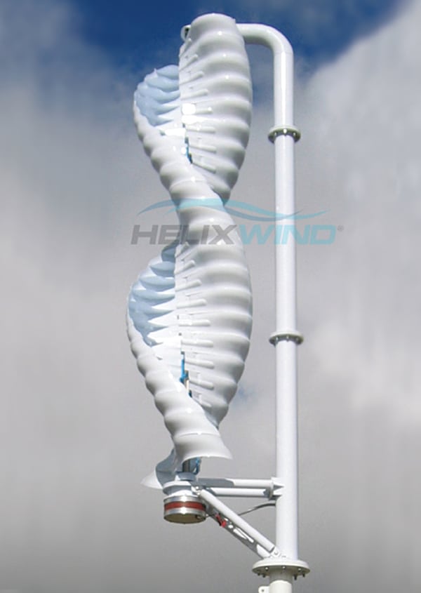 |
| 11. The Helix. California firm Helix Wind’s system is a Savonius, drag-based vertical-axis wind turbine. Courtesy: Helix Wind |
To gain traction in the competitive market, other VAWT makers have chosen to address HAWT shortcomings. UK firm quietrevolution claims its qr5, a helical VAWT designed to increase demand for wind turbines in environments close to people and buildings, is said to virtually eliminate noise and vibration while generating 7,500 kWh per year (Figure 12). So far, more than 100 turbines have reportedly been installed across the UK, Austria, and Germany.
 |
| 12. The quietrevolution. London-based quietrevolution’s qr5 VAWT is designed to eliminate noise and vibration. Courtesy: quietrevolution |
Airborne Turbines
Meanwhile, wind turbine design is also taking off in an entirely new direction—skyward. Prompted by suggestions that there is an estimated 870 TW of power potential in high-altitude tropospheric winds, and that the four-decades-old idea is finally technically feasible, several developers around world (including research labs and private industry) are testing prototypes that use kite-like attributes to harness wind energy. The concept is so close to reality that the Federal Aviation Administration has administered limits restricting airborne turbines to flight at altitudes below 600 meters.
One prominent example is the KiteGen power plant (Figure 13), which comprises several “Kite Steering Units” that pilot an array of “power kites” over a predefined flight path. KiteGen is typically arranged in a “carousel” or “stem” configuration. Modular approaches could allow developers to build plants up to 100 MW with costs of energy produced lower than €0.03/kWh, KiteGen says.
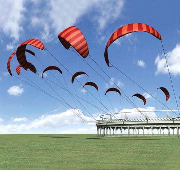 |
| 13. KiteGen. Arranged in a “carousel” or “stem” configuration, Italian company KiteGen’s power kites are tethered to a power plant and flown over a predefined flight path. Courtesy: KiteGen |
Joby Energy takes another approach. It is testing a 30-kW system (Figure 14) that looks like a multiwinged kite supporting an array of turbines. Thrust for the kite’s vertical takeoff is supplied by motor generators connected to the turbines, and the orientation is controlled by a computer system that differentially adjusts rotor speeds to keep it flying in a circular path.
 |
| 14. The Joby. California firm Joby Energy is evaluating a 30-kW multiwinged kite, while simultaneously designing and building 100- and 300-kW systems. Plans are to fly initial commercial systems between 500 and 2,000 feet high and to begin manufacturing commercial systems in 2012. Courtesy: Joby Energy |
In Germany, Festo (maker of pneumatic and electrical automation technology) is exploring the Aerois Enerkite system, which is an autonomously controlled kite wing of up to 24 square meters.
In the Netherlands, a system prototype of the Ampyx Power Plane, a glider plane that unwinds a winch during flight to propel a generator on the ground, has actually met its rating of 10 kW. The system is a spinoff of the TU Delft University’s Laddermill project. Peak power reached during a test of the Laddermill system in April 2010 was 20 kW.
In Switzerland, a coalition of academic researchers (including the University of Applied Sciences Northwestern Switzerland, the Swiss Federal Institute of Technology Zurich, and the Swiss Federal Laboratories for Materials Testing and Research) is evaluating high-altitude wind power.
Even China is stepping in, establishing a high-altitude wind energy research center in Guangdong Province, where plans are in place to build a 1-MW airborne wind power system in Foshan City.
Designs aren’t limited to kites and airplanes, however. A California company, Magenn Power, has developed an airborne wind energy system, MARS (Figure 15), consisting of a helium-filled tethered wind turbine that rotates on a horizontal axis at altitudes of 600 to 1,000 feet. MARS rotation also generates the “Magnus effect,” which provides additional lift, keeping the MARS stabilized.
 |
| 15. MARS. Magenn Power’s MARS helium-filled wind turbine can be deflated and redeployed. It is capable of operating in wind speeds from 4 mph to more than 50 mph. Courtesy: Magenn Power |
Other Turbines
An assortment of other turbines, typically a hybrid of HAWT and VAWT systems, exist—and are thriving. On the market, for example, is the Loopwind Wind Turbine, a high-torque, six-bladed turbine that captures wind with both front and rear blades. Japanese developers say that the design allows the Loopwing to be free of torque-imbalance suffered by VAWTs while being less affected by centrifugal force as compared with the propeller type. They also claim not only that the turbine rotates at wind speeds as low as 1.6 m/s but that it has a power coefficient of more than 40% in wind tunnel tests (with wind speeds of 8 m/s).
Among the “wackier” concepts are the larger, more ambitious architectural wind turbines. Several proposals have been made to integrate wind turbines into skyscrapers. The 600-meter-tall Anara tower in Dubai, for example, was designed to look like a massive wind turbine. Those plans were cancelled in 2009, but others are becoming reality. Last year, London saw completion of the £113.5 million Strata Tower (Figure 16), which generates a tenth of the power used by the building (a total of 50 MWh annually) via three five-bladed built-in turbines.
 |
| 16. Tower of London. The Strata Tower in London’s Elephant and Castle neighborhood is a 43-story, 147-meter-high building that features three five-bladed built-in wind turbines. Courtesy: Brookfield Asset Management |
Other concepts involve “biological” exteriors for buildings. Agustin Otegui, inventor of the “NanoVentSkin,” would incorporate tiny, biological self-repairing wind turbines into the outer layer of a building (Figure 17). “The outer skin of the structure absorbs sunlight through an organic photovoltaic skin and transfers it to the nano-fibers inside the nano-wires which then is sent to storage units at the end of each panel,” he says. “Each turbine on the panel generates energy by chemical reactions on each end where it makes contact with the structure. Polarized organisms are responsible for this process on every turbine’s turn.”
 |
| 17. Turbine skin. The NanoVent Skin concept from designer Agustin Otegui features miniscule bio-turbines that could clad buildings to generate power. Courtesy: Agustin Otegui |
Paradigm Shift or Yard Art?
Unconventional wind turbine designs have several things in common, small wind expert Mick Sagrillo told attendees at a small wind conference in 2009. Among these are roof-mounted or short towers, unconventional rotor configuration, “eye candy” photos, and a multitude of claims—which could range from “small and lightweight” and “only $0.25/watt” to “maintenance free” and they “generate even in low speeds.” What’s missing, he said, is that few developers want to talk about at which speeds the device can generate power, how it deals with turbulence, what its annual energy output or performance is, and if there is any field data that could point to how much power the device could produce per hour.
The hoards of claims made by self-styled inventors—“bozos and shysters,” as Sagrillo calls them—can be tested by considering simple parameters, he said. For example, swept area is inherently limited on rooftops, and rooftops and short towers experience increased ground drag and turbulence. Another factor to consider is that when the wind is down, cost is up. “What are we demonstrating?” he asked, “A ‘paradigm shift’ or yard art?” One way to resolve this is simple: eliminate what he calls “wet finger monitoring,” and get designs certified.
— Sonal Patel is POWER’s senior writer.