“Because droplet trajectories and deposition patterns cannot be modeled simultaneously with the liquid-film motion, physical-flow models cannot be used to accurately determine the collection efficiency of the final recommended liquid-collection system,” says the Electric Power Research Institute’s Revised Wet Stack Design Guide. This article offers a comparison of droplet deposition and entrainment in full-scale wet stack systems versus subscale flow models.
Modeling wet stacks started in the 1970s to help power plants prepare their existing dry stacks for wet operation, spurred by changes in environmental regulations on sulfur dioxide emissions. Three key Electric Power Research Institute (EPRI) reports were developed to educate the industry on what it means to operate a wet stack and how to properly design a liquid management system for it. They are:
- Entrainment in Wet Stacks (1982)
- Wet Stacks Design Guide (1997)
- Revised Wet Stack Design Guide (2012)
Two fundamental components of a wet stack study are the condensation calculations and the physical wet stack model. These components are used to analytically calculate the amount of liquid condensation and mist eliminator carryover that can be expected within the wet duct and stack system, and to perform scaled physical cold-flow analysis to aid in the design of a liquid collection system to collect and remove liquid from the system. These two components together allow one to make engineering decisions on liner material and ductwork insulation, design of liquid collection devices in the ductwork and liner, and sizing of system drainage.
A common misconception is that the models can be used to provide the liquid collection efficiency of the field installation. Simply put, this is not possible because there is no way to simultaneously simulate both the airborne droplets and the liquid films in a scaled model because we cannot scale gravity. Furthering the issue is the fact that a cold-flow model does not simulate the formation of condensation on internal surfaces.
The main objective of this paper is to demonstrate that it is not possible to model droplet trajectories and droplet re-entrainment simultaneously in a scaled physical-flow model, thus proving that the liquid collector efficiency results obtained from a scaled model have no correlation to the liquid collector efficiency of the field installation. A liquid collector efficiency value obtained from a scaled model is only a measurement of the collection efficiency of the model and does not represent the real-world stack performance.
The different sets of physics associated with droplet deposition and re-entrainment will be presented. A comparison will be made of the differences between the physics for droplets and liquid film layers in the full-scale field unit versus a scaled flow model. The implications with regard to liquid collector collection efficiency will be discussed.
Model Constraints
People sometimes ask for the liquid collection efficiency of the recommended liquid collection system for their wet stack application, where the collection efficiency would be defined as the ratio of the amount of collected liquid divided by the amount of incoming liquid. However, due to the constraints of physics when using a scaled cold-flow model, this is simply not possible.
Scaled cold-flow models are used to design the recommended liquid collection system for a wet stack installation. The flow models typically begin at the discharge face of the absorber mist eliminators and continue through the ducting to a point approximately four liner diameters above the top of the stack breaching duct. The model ducting typically includes at least two 90-degree turns (absorber outlet and stack inlet) along with other changes in flow direction such as bends and transition sections where the duct shape is changing.
Single-phase air-only flow modeling is a well-established practice that has been proven to provide accurate representations of the field gas flow patterns, velocity flow profiles, and pressure losses. Very different sets of physics are involved during two-phase gas and liquid flow modeling. There are several additional forces that must be accounted for in two-phase modeling such as the drag and acceleration forces on entrained droplets, gravitational forces, and the shearing forces on the liquid-film layers on the duct and liner surfaces. The interactions of these forces create different physical limitations in a two-phase flow model, thus requiring the model to be evaluated at completely different sets of flow conditions to properly model the liquid deposition in the ducts and re-entrainment processes in the stack liner.
For these reasons, it is physically impossible to obtain meaningful liquid collection efficiencies from a scaled physical flow model. The following sections will present the scientific evidence as to why it is not possible to use a scaled physical flow model to provide an efficiency of the field liquid collection systems that are recommended for wet stack applications.
Droplet Deposition and Liquid Motion in the Ducts
Liquid droplets are entrained in the gas flow throughout the absorber outlet ducting through various sources, mainly consisting of mist eliminator carryover and re-entrainment. Liquid films form on the duct and liner surfaces due to the deposition of the droplets and condensation. The entrained liquid droplets deposit throughout the ductwork due to gravitational forces and centrifugal forces along the curved streamlines of the gas flow through changes in flow direction.
Thermal condensation occurs when the saturated flue gas comes into contact with surfaces that are at or below the dew point temperature of the liquid. Thermal condensation is typically composed of a thin liquid film and is typically the dominant form of condensation throughout the ducting. This is especially true when the ducting is not insulated.
In order to correctly simulate the trajectory of droplets through the model, it is necessary to properly simulate the field acceleration forces on the droplets. The ratio of the gravitational and centrifugal forces must be the same in the model as in the field.
 |
|
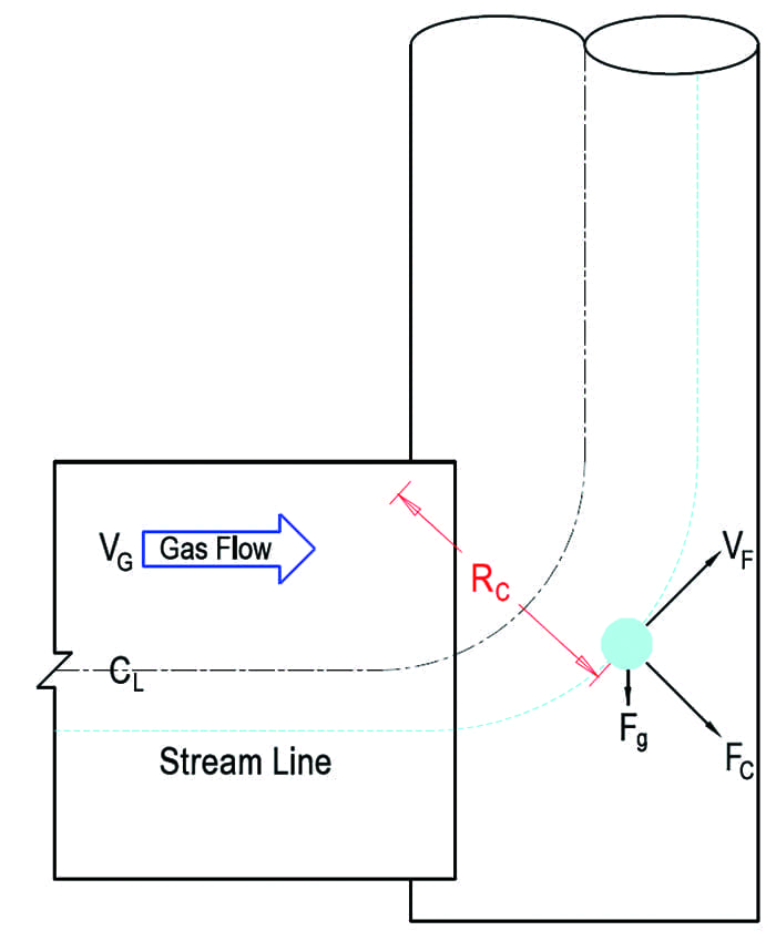
1. Forces on a suspended droplet, where CL is centerline of the duct, VG is gas velocity, Rc is curvature radius, Fg is gravitational force, FC is centrifugal force, and VF is field velocity. Courtesy: Alden Research Laboratory |
Figure 1 shows that the centrifugal force (Fcentrifugal) on a suspended droplet as it flows through a radius of streamline curvature (Rc) is equal to its centrifugal acceleration, or the velocity (V) squared divided by the radius of curvature. The equation for this relationship is:
Fcentrifugal = V2 / Rc
The trajectory of a droplet is properly simulated when the centrifugal acceleration of the field unit matches that of the model. This is depicted in the following equation in which the subscripts M and F are the model and field properties, respectively.
VM2 / RM = VF2 / RF
Rearranging the above equation to solve for the model velocity, results in:
VM = VF √(RM / RF) = VF / SF0.5
where SF is the scale factor of the test model.
 |
| Table 1. Comparison of important forces on a droplet through a turn. Source: Alden Research Laboratory |
In Table 1, typical field and model conditions were selected for illustrative purposes to compare the forces on a liquid droplet through a turn. A curvature radius of 24 feet and a liner velocity of 60 ft/sec have been assumed for the field unit and a model SF of 1:12 has been used in the calculations. As shown in the table, the gravitational forces and velocities are the same in the field and scale model; however, the centrifugal forces on a droplet are an order of magnitude higher in the model when the model velocity matches the field velocity. In order to properly simulate the trajectory of a droplet entrained in the gas flow, the model velocity would need to be set to 17.3 ft/sec for the given example.
Gas and Liquid Flow in the Liner
The saturated gas and entrained liquid droplets enter the vertical liner through the stack breach. The following thermodynamic and flow processes occur within the liner:
- ■ Thermal condensation along the full height of the liner.
- ■ Deposition of entrained droplets in the lower liner.
- ■ Pressure drop along the height of the liner.
- ■ Adiabatic condensation due to the pressure drop.
- ■ Turbulent deposition of condensation droplets along the full height of the liner.
- ■ Liquid film flowing down the liner due to gravitational forces.
- ■ Gas flow shear up on the liquid film along the full height of the liner.
- ■ Liquid re-entrainment from the surface of the liquid film by the gas shear.
- ■ Liquid re-entrainment at liner surface discontinuities.
- ■ Shear force up on the liquid film by the surface of the liner.
Most of the above forces are influenced by the behavior of the liquid film, which is strongly dependent on the wetting nature of the liner surface and the surface tension between the liquid and liner.
Droplet Deposition in the Liner and Re-entrainment from the Liquid Layer
Liquid films are formed on the full height of the liner surface by the turbulent deposition of entrained droplets and by condensation. The liquid film layer is controlled by the following forces: gravitational force, surface tension between the liquid surface and the gas, shear forces between the liner surface and the liquid film, and the gas shear forces on the liquid film. The significant forces are shown in Figure 2. At stack liner velocities above those recommended in EPRI’s Revised Wet Stack Design Guide, the resulting high gas shear or drag forces acting on the surface of the downward flowing liquid film are a major source of droplet re-entrainment and problematic stack liquid discharge.
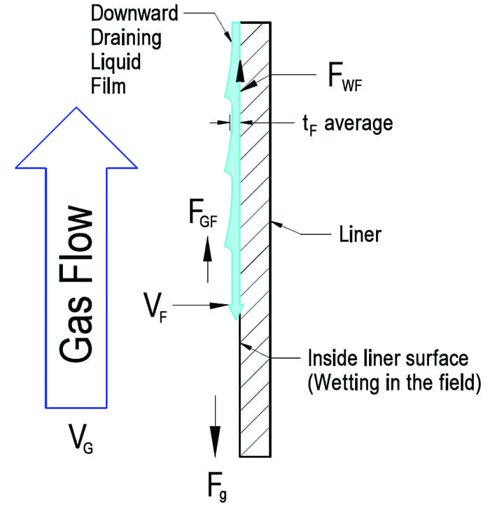 |
| 2. Significant forces on falling liquid film on the inside surface of a liner are shown here, where Fg is the gravitational force on the liquid film, FWF is the wall shear force on the liquid film, FGF is the gas shear force on the liquid film, VG is the gas velocity (up), VF is the liquid film velocity (down), and tF is the average liquid film thickness. Courtesy: Alden Research Laboratory |
To properly simulate the gas shear forces on the liquid film in the physical flow model, the model must be run at conditions that match the field gas shear forces. When the gas velocity heads (Pv) of the flow model and the field unit are equal, then the shear forces of the gas on the liquid in the model match the shear forces in the field. The velocity head is defined as:
Pv = (ρg x Vg2) / (2 x g0)
where Pv is the gas velocity head, ρg is the gas density, Vg is the gas velocity, and g0 is the gravitational constant.
In the equation below, the model velocity head (subscript M) has been set to match the field velocity head (subscript F).
(ρM x VM2) / (2 x g0) = (ρF x VF2) / (2 x g0)
Rearranging and solving for model velocity gives the following:
VM = VF x √(ρF / ρM)
Assuming a field liner velocity of 60 ft/sec, a field gas density of 0.066 lb/ft3, and a model air density of 0.075 lb/ft3, returns a model velocity of 56.3 ft/sec in order to properly simulate the field gas shear force in the liner of the flow model.
Implications and Conclusions
It has been previously shown by the examples given in this paper that the model velocity that is required to properly simulate the trajectory of a droplet entrained in the gas stream inside of the ducts is significantly different than the model velocity that is required to properly simulate the shearing forces of the flue gas on the liquid film layer in the stack. Therefore, it is physically impossible to simulate both effects simultaneously in a scaled physical flow model. When the model is set to match the droplet trajectories in the ducts, then the shear forces are not being matched inside the liner. Similarly, when the model is set to match the shearing forces, then the droplet trajectories are not correct.
The trajectory of entrained droplets and the re-entrainment of droplets from the liquid film layer are two very important aspects that must be evaluated in the flow model. However, the model needs to be evaluated at two widely different conditions in order to investigate these phenomena, so they cannot be modeled simultaneously. When the model is being used to evaluate re-entrainment from the liquid film layer, it must be run at conditions that match the field gas shear forces. This means that any re-entrained droplets will not have the proper trajectory and deposition patterns as would occur in the field, thus invalidating any reported liquid collection efficiency rates from the model.
Therefore, it has been shown that the modeling of droplet trajectories and the motion of the resulting liquid films cannot be modeled simultaneously in a scaled physical flow model. Because of this it is not possible to use a physical flow model to obtain the collection efficiency of a liquid collection system in an operating wet stack.
Research engineers at Alden Research Laboratory have done the work to identify the physical limits of wet stack modeling and developed a robust wet stack design program to provide clients with the essential engineering details needed to design an optimized wet stack system. The group developed a system to design wet stacks using analytics, scaled cold-flow physical models, and computational fluid dynamic analysis. The team’s work has been documented in numerous EPRI and self-published formats to educate the industry on what it means to operate a wet stack, and how to properly design a liquid management system for it.
Alden’s approach works within the bounds of physics to ensure responsible, accurate, and realistic results that are representative of the final field design. Simply put, the measurement of liquid collection efficiency in a scaled cold-flow physical model does not, and cannot, represent the field stack installation—it is literally just the performance of the laboratory model, with no correlation to the real-world application. ■
—Lewis A. Maroti is co-author of the EPRI Wet Stacks Design Guide. He has more than 45 years of consulting, and research and development (R&D) experience in the electrical utility industry, where he has been at the forefront of new developments and problem-solving in the area of air pollution control systems. David K. Anderson is a senior vice president with Alden Research Laboratory. He is the primary author of EPRI’s Revised Wet Stack Design Guide. He has more than 40 years of research and product development experience associated with power generation and environmental control systems, with a particular focus on physical and numerical modeling. James M. Daniel is a senior engineer at Alden Research Laboratory. He has more than 18 years of consulting, and R&D experience in the electric utility industry. His particular expertise is in the area of physical flow modeling related to utility and industrial emissions, and process equipment.