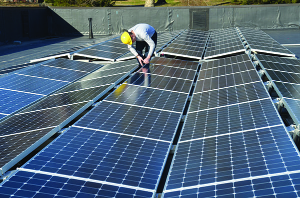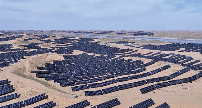

Utility-scale solar farms are essential players in the energy transition. But with growth comes more exposure, and large solar arrays are particularly vulnerable to natural disasters, especially hailstorms.
As extreme weather events become more frequent and severe, utility executives, plant managers, engineers, and energy policymakers need proven, scalable methods for assessing and repairing solar farm damage quickly and effectively.
Best practices in solar farm damage evaluation are evolving, shaped by real-world forensic engineering experience and the rise of new inspection technologies. By understanding the strengths and limitations of available tools and testing strategies, plant owners and insurers can make smarter decisions, reducing downtime, controlling repair costs, and safely restoring renewable power generation.
Realities of Large-Scale Solar Damage
Evaluating storm damage at a large solar site isn’t as simple as sending out a team of inspectors. These sites often span hundreds of acres, contain hundreds of thousands of photovoltaic (PV) modules, and access can be limited. Historical baseline data about module performance or layout may be missing.
This article is part of POWER’s annual special edition published in partnership with the RE+ trade show. This year’s event is scheduled for Sept. 8-11, 2025, in Las Vegas, Nevada. Click here to read the entire special issue, and if you’re attending RE+, be sure to connect with the POWER team at our booth on Venetian Level 1—V3046.
Furthermore, differing terrain or vegetation growth can complicate navigation, requiring teams to use specialized vehicles or even handheld equipment to reach remote zones. Add to this the fact that most site operators, contractors, and adjusters have limited experience navigating large-scale solar damage, and the risks of misdiagnosis or delayed resolution become clear. What’s more, site owners may be managing multiple layers of stakeholders, including insurers, equipment manufacturers, and investors, which can slow decision-making when time is of the essence.
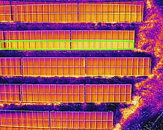
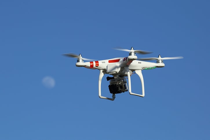
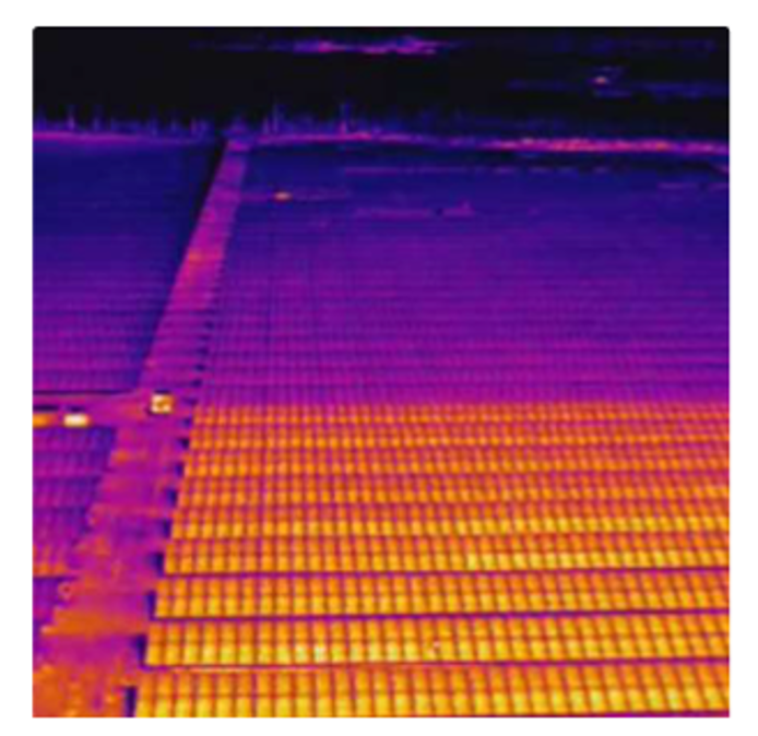
Drone-based thermography has gained popularity as a non-contact, aerial method for assessing damage. This infrared (IR) technique uses cameras mounted on drones to detect anomalies in temperature, such as hotspots, defective strings, or inverter failure. Advanced software, sometimes powered by artificial intelligence (AI), then interprets these images to identify potential problem areas across the site.
However, while drone-based thermography (Figure 1) can be helpful, it should not be seen as a standalone diagnostic tool. The method is highly weather-dependent; wind, cloud cover, precipitation, and frost can all distort results. Camera angles and drone altitude also affect image accuracy, and without pre-damage thermal scans for comparison, it’s difficult to assess degradation conclusively. Some damage types, such as microcracks in module glass, don’t show up in IR scans at all.
Many drone-based thermography scans are analyzed by AI algorithms to identify defects. These algorithms are often not trained to spot unique and abnormal failures. Lightning strikes and hailstorms are two common weather events that create unique damage patterns that AI-based thermography detection struggles to identify.
Moreover, thermographic data often lacks the resolution needed to differentiate between a functional defect and surface dirt or shading issues. Misinterpreting these anomalies can lead to unnecessary repairs or missed problem areas. In short: drone imagery is a valuable supplement, but not a substitute, for ground-based diagnostics and methodical testing protocols.
Building a Smarter Testing Plan
Rather than defaulting to costly, comprehensive testing across an entire solar site, engineers should approach diagnostics strategically, combining inspection methods that deliver actionable data efficiently. Below are several key testing strategies and how they fit into the damage evaluation and repair process.
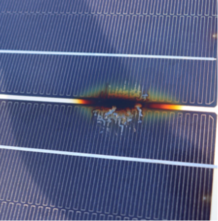
Visual Inspection: This remains one of the most effective tools, particularly when integrated into a structured walk-through with trained personnel capturing labeled images and damage tallies per combiner box or block. Damage can be noted directly on as-built drawings to support streamlined remediation. Photos (Figure 2) should include metadata such as timestamp and geolocation to verify findings and support insurance claims.
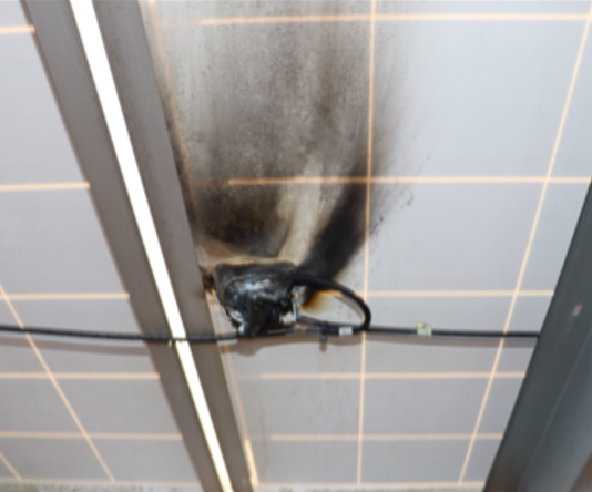
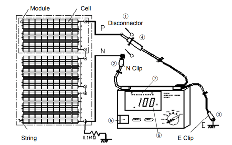
Insulation Resistance (IR) Testing: This test (Figure 3) checks the integrity of wiring insulation and detects ground faults. It’s not weather dependent, is inexpensive to perform (equipment under $1,000), and applicable at multiple points: modules, strings, or combiners. It is particularly effective for identifying latent faults in string wiring that could pose fire risks or safety hazards if left unresolved.
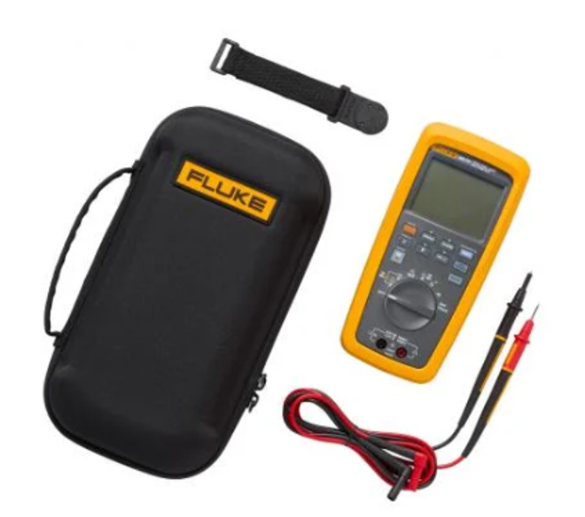
Voltage Open Circuit (Voc) Testing: A solar module’s open-circuit voltage is not as dependent on the irradiance levels as the current. Therefore, Voc testing (Figure 4) helps confirm whether modules or strings are producing expected voltage under open-circuit conditions. It’s a quick “go/no-go” check that can be done during daylight, with minimal weather influence. It is often used to validate visual damage observations or highlight discrepancies in string-level performance.
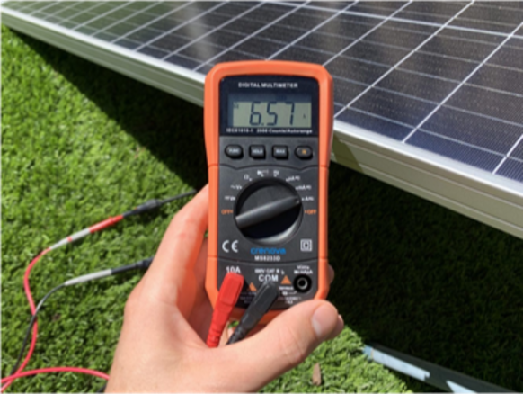
Short Circuit Current (Isc) Testing: Used less frequently in the field due to its complexity, Isc testing (Figure 5) assesses current capacity under short-circuit conditions. It’s typically employed at the module level and requires an understanding of circuit topography. Its diagnostic value increases when paired with IV curve tracing, providing a fuller picture of electrical performance degradation.
IV Curve Tracing: This test (Figure 6) plots current versus voltage at various loads, offering a detailed view of module performance. It’s effective during repair commissioning but requires sunlight and can be cost-prohibitive at small scale, as equipment costs range from $5,000 to $20,000 depending on system voltage.
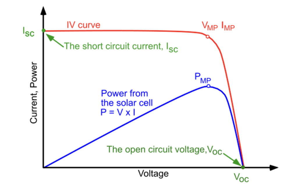
Nonetheless, for high-priority areas, such as central arrays or locations with repeated failures, this test can prevent unnecessary replacements and verify long-term reliability.
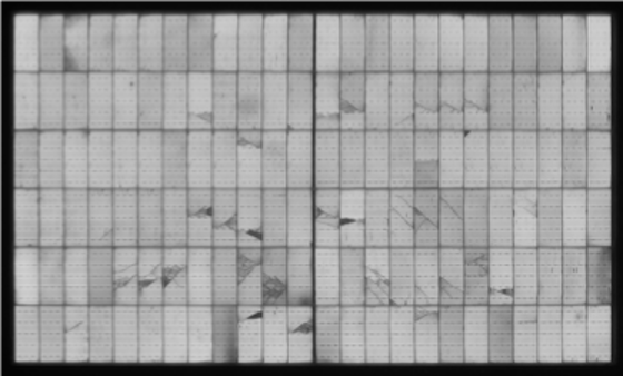
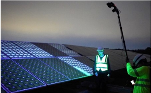
Electroluminescence (EL) and ultraviolet fluorescence (UVF) scanning: Both EL and UVF (Figure 7) can detect microcracks and degradation at the cell level. However, they are expensive, labor-intensive, and not always suitable for large-scale application. EL scanning must be performed at night or indoors. UVF only works with certain module types and is also light-sensitive.
The bottom line: Effective damage evaluation means choosing the minimum effective combination of tests, not the most tests. As one seasoned forensic engineer put it, “If voltages are good and output is strong, a follow-up drone scan might not even be necessary.”
Developing a Thoughtful Repair Plan
Once damage is documented, having a clear, phased repair plan is crucial. A solid repair strategy doesn’t just improve efficiency, but it also helps reduce business interruption losses and supports clear communication with insurers.
Collaboration among forensic engineers, repair crews, and third-party consultants during the planning stage can prevent rework and redundant site visits. Some best practices include:
- Clarify repair methods early: Agree on testing approaches and scope with all stakeholders upfront to avoid mid-project confusion.
- Prioritize critical areas: Focus repairs on sections that pose the greatest risk to output or safety. Phased work allows partial power restoration sooner.
- Incorporate fixes during evaluation: Technicians should carry tools and replacement connectors during damage walks. Reconnecting or replacing elements on the spot, when feasible, saves time and money.
- Avoid commissioning overkill: In many cases, if voltage and power output check out post-repair, additional testing can be limited.
A useful tracking system, often just a detailed spreadsheet, can monitor damaged module counts, repair status, and test results. This documentation not only helps with immediate repairs but serves as a reference point for future storms or claims.
Tailoring Repair Oversight to Site Complexity
Monitoring repair progress is important, but over-monitoring adds unnecessary cost. The level of oversight should be matched to project size, contractor experience, and communication flow.
Clear checklists, daily progress reports, and milestone reviews can help maintain accountability without bloating the project budget. By aligning monitoring strategy to site needs, stakeholders can control costs without sacrificing quality or safety.
Cost estimation in solar farm repairs follows the same principles as other large-scale construction work. The key difference is repetition. Damage typically affects many identical units, panels, wires, connectors, which simplifies unit pricing but amplifies error margins if miscalculated.
Misjudging even a single unit cost by $10 across 10,000 modules can result in six-figure discrepancies.
A repair cost model should include:
- Labor (hours and rates per task).
- Materials (replacement panels, connectors, wiring).
- Equipment and subcontractor fees (e.g., drone services, testers).
- Mobilization and general conditions.
- Project management and testing overhead.
Accurate unit pricing ensures insurance reserves are set appropriately and helps avoid disputes down the line.
Lessons from the Field: Avoid Common Pitfalls
In real-world solar damage investigations, we’ve seen several recurring challenges:
- Data gaps due to missing baseline imagery or incomplete as-built records.
- Test overkill that doesn’t contribute meaningful information.
- Unqualified contractors who misinterpret test data or fail to meet DC wiring workmanship standards.
- Poor communication between stakeholders, slowing repair timelines and inflating costs.
These issues highlight the importance of bringing in experienced forensic engineers early, especially those familiar with both electrical systems and utility-scale solar. Pre-storm preparation, including updated as-builts and operational benchmarks, can also improve post-event diagnostics.
Conclusion
As solar continues its rapid expansion, the industry must evolve its approach to damage assessment and repair. That means combining high-tech solutions like drone-based thermography with proven, practical methods like visual inspection and strategic testing. It means empowering contractors to perform real-time fixes during evaluation and tailoring oversight to project scale. And it means prioritizing data-driven decisions: avoiding unnecessary delays, costs, or commissioning redundancies. In the end, the goal is simple: Get clean power back online, safely and quickly.
—Britton C. Hager, P.E., is a forensic engineer with Engineering Design & Testing Corp.