In cooling water chemistry for power plants, it is not enough to control one or two of the major chemistry issues. Successful treatment requires simultaneous control of corrosion, scale, and microbiological fouling. These three are so strongly tied to each other that if one is allowed to go out of control, the other two soon will be.
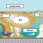
There is a synergistic relationship among the three major cooling water treatment issues: corrosion, scale or deposit formation, and microbiological fouling. In order to control one, you need to control all three (Figure 1). And, to make things harder, sometimes the treatment strategies used to fight one side of this triangle can actually wind up enhancing another side.
 |
| 1. Scaling, biofouling, or corrosion? Answer: Yes. Courtesy: M&M Engineering Associates Inc. |
Take, for example, the common use of bleach as an oxidizing biocide. At the proper cooling water pH, bleach can be an excellent biocide. Its cost and availability certainly make it the most commonly used. However, bleach is inherently corrosive. It is a nondiscriminating oxidizer. It will oxidize carbon steel as quickly as it will oxidize biofilms. Then, the roughened up surfaces of the corroded carbon steel have many more nooks and crannies and crevices available for microbiological colonies to be established in places where they can hide from the bleach. Bleach may also oxidize treatment chemicals used to minimize scaling or corrosion.
Then there’s the relationship between scaling and biocide effectiveness. Scaling deposits in condenser tubes and in the cooling tower provide excellent surfaces for biofilms to attach and microbiological colonies to develop. The biofilms consist primarily of exo-polysaccharides, which are “sticky” and will collect deposits and debris to use as a food source and to create a shelter to protect themselves from the elements and, in particular, biocides such as bleach. Some research has even shown that the biofilm structure itself creates surface conditions that promote incipient crystal formation and accelerate growth.
Of course, the fact that microbiological species accelerate corrosion is well documented. It even has its own name— microbiologically influenced corrosion (MIC)—and it is ubiquitous. Biofilms cause can cause general oxygen pitting by establishing a concentration gradient between the fully oxygenated cooling water and low-oxygen or even fully anaerobic conditions under the biofilm. The anaerobic conditions found at the base of the well-established biofilm promote the growth of anaerobic bacteria such as sulfate reducing bacteria. These bacteria convert sulfate in the cooling water to sulfide and produce an acidic hydrogen sulfide molecule that is very corrosive to a variety of steel alloys, including stainless steel and even copper alloys, which are generally more immune to attack from the aerobic bacteria. Other bacteria that grow in biofilms metabolize metals directly for energy or use metallic corrosion products.
Now that we see how these three factors work together to cause trouble in cooling systems, let’s attack each individually and review aspects of a good cooling water program that achieves control of all three.
How to Control Biofilms in a Cooling System
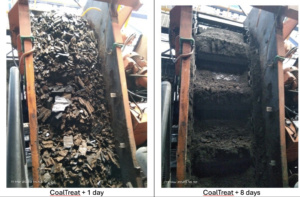
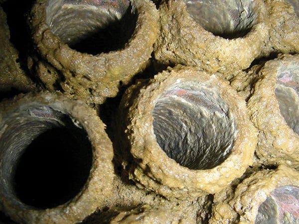
Besides the specter of MIC chewing on the metallic parts of your cooling system (Figure 2), accumulations of biofilms also inhibit heat transfer in the condenser tubes and can accumulate on cooling tower fill to the point where it can collapse the fill support and cause significant damage to a cooling tower.
 |
| 2. When being green is bad. Control of microbiological fouling is critical. Courtesy: M&M Engineering Associates Inc. |
The key to maintaining control over microbiological populations in power plant cooling water is to provide a consistent level of treatment throughout the year (see sidebar). That is, the treatment needs to be consistently effective. The actual concentrations of biocide required to provide this level of treatment may change significantly, depending on cooling water conditions and the environment.
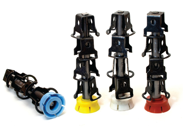
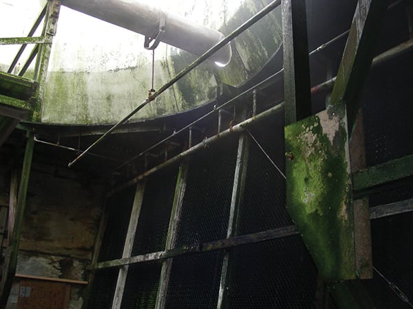
Cleaning or Maintaining? I’m indebted to one expert in this field for a statement I’ve used many times in discussing cooling water treatment with clients. George Licina of Structural Integrity taught me: “It’s just like your mother told you—it’s easier to keep your room clean than to get your room clean.” The same goes for your cooling water system: Consistent application of the right amount of biocide or biocides for the conditions in your cooling water will keep your “room clean” and help control scaling and corrosion (Figure 3).
|
Some power plants find that they can shock treat the cooling water system for an hour a day during most of the year and cut back to once or twice a week during the winter while still properly controlling biofouling in their system. Other power plants not only require daily or even continuous feed of bleach but also need to add additional nonoxidizing biocides during the summer months.
The most common (though still imperfect) method for determining that you are adding sufficient oxidizing biocide to control microbiological fouling is still the free chlorine test (DPD test). This is a minimum and should be performed during each chlorination cycle, or daily for those that continuously chlorinate. As conditions change (seasons and temperatures) the amount of bleach required to produce the desired free available chlorine residual will change, and the plant should respond by increasing or decreasing the biocide feed rate accordingly. Note that oxidation reduction potential (ORP) is not a good indication of microbiological control in cooling water. ORP is no substitute for testing free available chlorine.
Getting the Full Benefit from Chlorine. A full discussion of the various types of biocides (both oxidizing and non-oxidizing) and optimizing strategies for their use is beyond the scope of this article. But it would be good to say a few words about the most common biocide used in power plants: chlorine.
Previously, the most common source of chlorine was chlorine gas shipped to power plants as a condensed liquid in 1-ton cylinders. It was evaporated and swept into the cooling water lines as a gas. When chlorine gas dissolved in water, it formed hydrochloric acid and hypochlorous acid. The hydrochloric acid lowered the cooling water pH slightly, which enhanced the effect of hypochlorous acid as a biocide. Obvious concerns about safety were the primary reason that power plants moved away from the use of 1-ton chlorine cylinders to liquid (sodium hypochlorite) commercial bleach delivery.
Commercial bleach is typically supplied at 12.5% or 10% chlorine. One pound of chlorine gas makes 0.74 pounds of hypochlorous acid, whereas 1 gallon of 12.5% bleach has the potential to generate 0.875 pounds of hypochlorous acid, if there is sufficient hydrogen ion (low enough pH) in the cooling water to form the acid.
Commercial bleach is generated by bubbling chlorine gas into a caustic solution. Some extra caustic purposefully remains in the bleach to attempt to slow the decomposition of hypochlorite to chlorates. The typical pH of commercial bleach is between 11.5 and 13.5. Bleach solutions that have a pH of 11 or less decompose very rapidly.
Therefore, in strong contrast to the use of chlorine gas, the use of bleach has the potential to increase the pH of the cooling water. It is been mentioned numerous times that hypochlorous acid (HOCl) is much more effective as a biocide than the hypochlorite ion (OCl-); therefore, bleach in particular loses its activity as a biocide in high-pH cooling waters.
Sodium hypochlorite solutions start decomposing the minute they are manufactured. They decompose primarily along two chemical pathways: by the formation of chlorate (ClO3-) and by the release of oxygen (ClO- to Cl- + O2). In a good quality hypochlorite solution, the formation of chlorate is the primary decomposition pathway. A variety of factors can accelerate the decomposition of bleach. The most critical are time, temperature, exposure to ultraviolet (UV) radiation, and concentration:
■ Time. All bleach decomposes over time (Figure 4). One source calculated that at a 90F storage temperature, a 10% bleach solution loses half its effective hypochlorite concentration in 95 days. Although you may use up a tank of bleach in a few weeks, you may want to ask your supplier how long your bleach has been in storage prior to its arrival at your facility.
■ Temperature. In 60 days at 68F storage temperature, bleach will have lost about 17% of its hypochlorite, whereas at 90F it will have lost about 55%. The ambient temperature should be a consideration in the placement of a hypochlorite storage tank.
■ UV radiation. The UV rays in sunlight are very effective at decomposing bleach solutions. All bleach tanks should be made of UV-impervious materials or coated in such a way to exclude UV light. Better yet, put them inside.
■ Concentration. The more concentrated the bleach solution, the faster it decomposes. If your site is not large user bleach, it may be best to stick with the 10% bleach solution instead of the higher concentration.
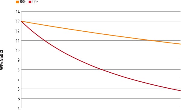 |
| 4. Bleach degradation rate versus time. Source: Bernard Bubnis, “Understanding Bleach Degradation,” NovaCem Laboratories Inc., Oxford, Ohio |
Other factors that can have an effect on the degradation rate include the concentration of salts (chlorides) and transition metals (Ni, Cu, Co) that may get into the bleach from the caustic used in its manufacture or in tank and piping materials where the bleach is stored. The level of nickel in the bleach should be less than 0.1 mg/l and copper should be less than 1 mg/l.
Testing Bulk Chemicals Is Essential. It behooves the chemistry personnel at the plant to check the concentration of hypochlorite in each shipment of bleach before it is offloaded into their tank. One plant questioned why it was suddenly not achieving a free available chlorine residual in its cooling water, as it had in the past. A check of the bleach bulk tank found that the concentration in the tank was only 2.5% bleach. Evidently, the previous bleach delivery was not the 10% bleach the supplier claimed it was. Simple hypochlorite test kits are available for this purpose.
Bromine Is Not a Biocide. Sometimes I hear people referring to their cooling water chemistry as “bromine” chemistry. Bromine is a reddish-brown gas and highly toxic (like its neighbor in the periodic table—chlorine gas). Is not something that should ever be generated at a power plant. The use of sodium bromide to enhance the biocidal properties of bleach at higher cooling water pH values, however, is very common. We discussed the proper application and blending of these two chemicals to produce the maximum amount of hypobromous acid in “Biofouling Control Options for Cooling Systems” in the September 2007 issue (available in the Water Treatment Guidebook, available in the Store at powermag.com.)
Is important to remember, however, that sodium bromide is not a biocide; it is a simple salt, with no biocidal properties. It is only when it is properly reacted with hypochlorous acid (not bleach—which is predominantly hypochlorite ion) that it will form hypobromous acid, which is the desired biocide.
Stabilized hypobromous acid is available a number of chemical vendors. This eliminates the need to properly mix the bleach and sodium bromide on site. However, it is more expensive to buy the stabilized hypobromous acid than to generate it.
Scale Prevention for Power Plant Cooling Water
By far the most common cooling water scale is calcium carbonate, though other scales can often be just as detrimental and far more difficult to remove. These include calcium sulfate, calcium phosphate, and various forms of silica deposits.
The Calcium and Conductivity Connection. The inverse solubility of calcium compounds such as these cause scaling in condenser tubes, which can severely affect heat transfer across the condenser, increase the unit back pressure, and restrict the unit’s generation. In recirculating systems (cooling towers) the cooling tower blowdown is often controlled by the conductivity of the cooling water. It is important to remember that conductivity is only a proxy for the real control parameter–calcium. Conductivity can be easily and continuously monitored and therefore has a much better chance at controlling the cooling water calcium than any other parameter.
However, there are cases where this proxy breaks down. If your cooling tower makeup water comes from multiple sources, or if the chemistry of these sources has changed over time, then the assumptions for the cooling water chemistry control parameters (including the conductivity control limits and chemical feed rates) will also have changed.
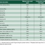
Besides conductivity and pH, there should always be a specified limit on total hardness and calcium hardness in your cooling water program. The lab should test the cooling water regularly for these parameters, and these limits should always override the conductivity limit. One zero-liquid discharge (ZLD) plant occasionally fed water from the ZLD clarifier/softener effluent back to the cooling tower when it could not be used in the downstream portion of the ZLD. This water was high in conductivity but very low in calcium, which dramatically skewed the conductivity control of the cooling tower and the amount of anti-scalant being added.
Ensuring Consistent pH. The pH of cooling water is the other critical factor for preventing scaling. If pH control with sulfuric acid is part of your cooling water chemistry program, it should be understood that it is a critical part.
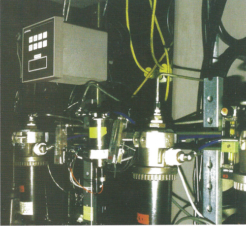
A sulfuric acid pump malfunction or problem with the pH controller for the pump can cause serious scaling or corrosion issues in the cooling tower. Both the acid pump systems and pH control elements on the cooling water should be redundant. There should either be two separate cooling water pH probes at different locations, or the pH of the cooling water should be checked frequently by the lab or operations and compared to the pH of the online analyzer. Both the lab and operations should be aware of the potential damage that can be caused when they are not operating properly and know what actions to take if problems arise.
Anti-Scalant Best Practices. Anti-scalant chemicals are a tremendous benefit to maintain and clean a condenser. It goes without saying that these chemical pumps are also critical.
Anti-scalants can be grouped into two broad categories: phosphonates and polymers. There are polymers that have anti-scaling properties and other polymers that act as a general dispersant to keep silt from depositing on the condenser tubes. Often, a cooling water treatment will contain both an anti-scalant and a polymeric dispersant.
Is important to remember that the critical area for precipitation is in the condenser tubes (see sidebar, next page). This is where elevated temperatures will cause the precipitation. In some cases, overtreatment of these chemicals is not only expensive but also detrimental to other plant processes. In cooling lakes, precipitation of calcium carbonate in the shallow areas of the lake is something to be encouraged, as it reduces the soluble calcium levels in the water. Overtreatment has prevented this “self-softening” mechanism, resulting in a sudden massive scaling when the anti-scalant could hold no more.
| Anti-Scalant: Not Too Much; Not Too Little; Just RightThere are a variety of scaling indices (Ryzner, Langelier, and Practical Scale Index) and an excellent software package (www.frenchcreeksoftware.com) that can be used to predict the potential for scaling to form in the condenser tubes. These can help a plant to adjust the anti-scalant chemical feed to its “just right” level. Use of these indices requires accurate and regular testing of a number of parameters that your laboratory should be doing already. |
In ZLD plants where the cooling tower blowdown water is treated and recycled, the amount of anti-scalant used in the cooling tower can have severe consequences in the precipitation processes generally used as part of the ZLD treatment. Therefore, the amount of phosphonate or polymer treatment that is fed to the cooling water also needs to be adjusted frequently, based on a variety of chemistry and physical factors. Those chemistry factors include pH, total hardness, calcium, total alkalinity, phosphate, phosphonate (in cooling towers), and silica. Physical factors include the temperature of at the condenser outlet and the velocity of the water through the tubes.
In some power plants, velocity of the cooling water through the condenser tubes can be changed by the number of circulating water pumps in use. The use of one pump versus two, or two pumps versus three, can make a significant difference in the ability of the anti-scalant to keep the tubes free of scale for the few seconds that the water is in the hot condenser tubes.
Biofilms create a natural resistance to flow through the tube, thus slowing the velocity. Debris can also plug or partially plug tubes, reducing the velocity through the tube. Keeping the tubes clear and water boxes clean gives anti-scalants the best possible opportunity to prevent scale accumulation.
The condition of the cooling water intake screens can have a significant effect on scaling of the condenser tubes. Some cooling water systems get additional help from side-stream filtration of the cooling water. Removing particulate from the cooling water enhances the effectiveness of the chemical treatment.
Because the critical area for the anti-scalant is the condenser tubes, is important that the anti-scalant chemical is well mixed in the cooling water flow just prior to the tubesheet. Adding the chemical too close to the water box may not provide sufficient mixing; adding it far away from the water box can reduce its effectiveness by having it consumed on the walls of the cooling water pipe before it reaches the condenser.
 |
Approaches to Controlling Corrosion
Gone are the days when we could prevent corrosion in cooling water systems with an active corrosion inhibitor (remember the days of zinc chromate?) More recently, the two primary chemical methods for controlling carbon steel corrosion in the cooling system have been to raise the pH of the cooling water close to 9.0 or to add orthophosphate to the cooling water treatment to form an iron phosphate protective layer on the carbon steel.
There are issues with both of these approaches. Raising the cooling water pH to around 9.0 drastically reduces the ability of conventional bleach to control microbiological growth. Even hypobromous acid effectiveness drops off significantly at high pHs. Therefore, microbiological control of these systems can be a daunting task requiring higher treatment levels or the addition of nonoxidizing biocides. And biofilm growth leads to corrosion.
When the pH is controlled with sulfuric acid, the additional orthophosphate used in the treatment can have unwanted side effects. In cases where the calcium level in the tower becomes excessive, calcium phosphate or calcium sulfate can precipitate out on a variety of surfaces. These deposits can be tenacious and difficult to remove. In cases where orthophosphate is used as part of the treatment program, it is very important to determine the amount of orthophosphate and the amount of calcium hardness in the cooling water on a regular basis and calculate the potential for calcium phosphate saturation.
In cases where cooling tower makeup is a treated wastewater, the incoming water can have varying levels of orthophosphate, making control of the orthophosphate level in the cooling water very difficult.
Orthophosphate also acts as a “fertilizer” for a variety of microbiological species, and this may affect the amount and types of biocides used to maintain a relatively clean condenser and cooling tower. Cooling water systems operating at pH values just above 7 need to carefully monitor a variety of parameters to ensure that they are neither corroding, nor scaling, nor accumulating biofilms.
For those condensers that have copper alloy tubing, or where the cooling water also comes in contact with copper alloy tubed heat exchangers, copper corrosion is typically controlled with a type of azole. Tolytriazole (TTA) is in common use, though it is been shown to be very sensitive to bleach.
One manufacturer (Mexel USA) claims to have developed a type of filming amine capable of laying down the protective chemical layer on the surface of the circulating water piping to prevent corrosion. The company claims that this slick surface has other benefits, such as minimizing the ability of biofilms to stick to the surface. This would be a very interesting development, if it proves to be durable and cost-effective for large cooling water systems.
At the very least, it is critical that corrosion rates in the cooling water are monitored on a regular basis. Corrosion coupon racks are a minimum. But they only tell you what has happened generally over the past 30, 60, or 90 days. To determine the instantaneous corrosion rates on the circulating water system linear polarization resistance probes (for example CORRATER probes) have been shown to provide reliable information on a real-time basis.
— David Daniels (david_daniels@mmengineering.com) is a frequent contributor to POWER and senior principal scientist at M&M Engineering Associates Inc.