With natural gas serving as the fuel de jour, many utilities and merchant generators will be considering the purchase of new combustion turbines in the near future. If you are in the market for a gas turbine, here are some key design features you should discuss with turbine vendors prior to your next purchase.
The growth of the combustion turbine (CT) market over the past two decades has been facilitated by progress in three technologies:
- Metallurgical advances that have made possible high temperatures in turbine components (especially turbine blades) and combustors.
- The advancement of aerodynamic and thermodynamic knowledge (especially from aircraft and spacecraft industries).
- Advanced computer technology used in the design and simulation of turbine airfoils, combustors, and turbine blade cooling configurations.
Combined, these advances have made possible CT designs with state-of-the-art 1,600C (2,912F) turbine inlet temperatures and combined-cycle efficiency pushing the 60% thermal efficiency barrier.
The challenge for a purchaser of a new CT is what questions to ask, given that these design advances are not readily apparent. The discussion that follows is not meant to tell a manufacturer how to design a CT, nor is it comprehensive. Rather, it is intended to prompt some useful planning before a potential buyer has the first technical discussion with a potential supplier.
Turbine Configurations
CTs are usually categorized as either heavy frame industrial or aero-derivative gas turbines, although a few turbines have recently adopted features of both design types. One good example of a “hybrid” is General Electric’s LMS100; it has a Frame 6FA low-pressure compressor and a CF6-80C2 high-pressure compressor.
In general, the differences between the aero-derivative and industrial turbines are weight, size, combustor and turbine design, bearing design (antifriction bearings for aero-derivative turbines and hydrodynamic ones for industrial turbines), and the lube oil system. Industrial turbines are also field erected and maintained in place, whereas aero-derivative turbine plants are designed for a quick replacement of the entire engine when maintenance is required.
Manufacturers of aero-derivative CTs include General Electric, Rolls Royce (Figure 1), and Pratt & Whitney. Manufacturers of industrial CTs include Siemens (Figure 2), Mitsubishi (see page 54), Alstom (Figure 3), General Electric, and Solar Turbines Inc. Each manufacturer’s CT is available in 50-Hz and 60-Hz models.
 |
| 1. Rolls Royce RB211. The 44-MW engine upgrade released by Rolls Royce in mid-2010 boasts a 41.5% thermal efficiency. The high-pressure turbine and much of the triple-spool compressor is based on aero engine technology. Courtesy: Rolls Royce |
 |
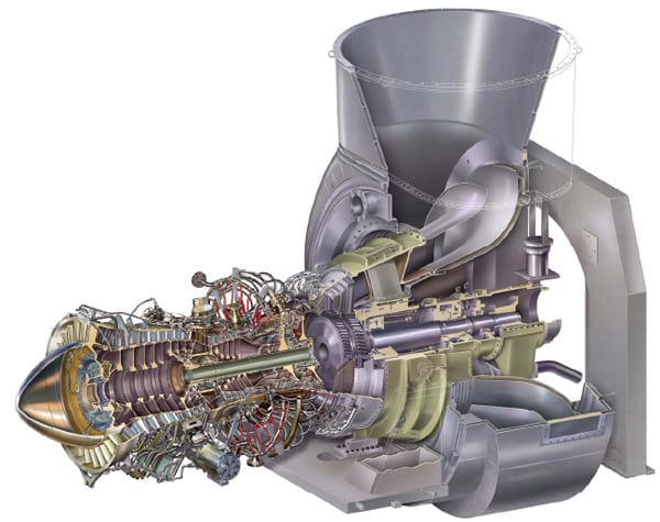
| 2. Siemens SGT6-8000H. Siemens Energy introduced the 60-Hz version of its combustion turbine in June 2010. The 274-MW turbine features a turbine inlet temperature of 1,500C. This turbine can go from standby to start in 5 minutes and can reach full power in 15 minutes. Courtesy: Siemens Energy |
 |
| 3. Alstom GT24/26. The sequential combustion system is a unique feature of the GT24/26. Compressed air is heated in the first combustion chamber (EnVironmental or EV combustor) by adding about 50% of the total fuel (at baseload). The pressure is halved after the combustion gases expand through the single-stage high-pressure turbine. The remaining fuel is added into the second combustion chamber (Sequential EnVironmental or SEV combustor), where the combustion gas is heated a second time to the maximum turbine inlet temperature. The gas then expands through a four-stage low-pressure turbine. Courtesy: Alstom |
Selection of CT type is usually made based on the nature and location of service and a long list of site-specific design and economic factors that are usually led by the projected price of natural gas. The conventional wisdom was once to place aero-derivative units in remotely located applications (including offshore) and to place heavy frame industrial units in easily accessible baseload applications. However, about 10 years ago in the U.S., the combined cycle, based on the aero-derivative turbine, became very popular given both the speed at which a plant could be constructed and its superior efficiency.
Both CT types are available in different configurations. In the hot-end-drive configuration the output shaft is at the turbine or exhaust end, where the higher temperatures can affect bearing life and make servicing of those bearings more difficult. In the cold-end-drive configuration, the output shaft extends out the front of the compressor, allowing the exhaust gas flow to be axial in some models (Figure 4). With a cold-end-drive turbine, the driven equipment is also relatively cooler and easier to service. However, the compressor inlet and ducting must be configured to accommodate the output shaft and the driven equipment. In sum, the CT configuration is usually selected, when possible, by application and site configuration.
 |
| 4. Cold-end-drive option. The typical single-shaft combustion turbine has the compressor and turbine sections on opposite ends of the shaft. The driveshaft in this figures extends from the compressor section, hence it is a cold-end-drive engine. If the driveshaft extended from the turbine end, it would be a hot-end-drive engine. Source: WorleyParsons Services Pty Ltd. |
Single-spool, integral output shaft CTs (in both hot-end and cold-end-drive configurations) are used primarily to drive electric generators. However, the high torque required to start pumps and compressors under full pressure results in high turbine temperature during the start-up cycle when internal cooling airflow is low or nonexistent. The solution has been to connect a single (or two or three) spool compressor/turbine section (also called a gas generator) that produces hot gases to a separate power or free turbine. The gas generator is not physically connected to the power turbine shaft but is coupled aerodynamically (Figure 5). Also, the power turbine can be designed to operate at the same speed as the generator, not the gas generator, and often eliminates the need for a gearbox to match speeds. (Typical gearbox losses are 2% to 4% of power.)
 |
| 5. Two-shaft option. The typical two-shaft or split-shaft combustion turbine configuration places the compressor and gas generator turbine on a common shaft. The hot exhaust gases “aerodynamically” connect the power or free turbine to produce shaft power for the generator or other driven load. The advantage of this configuration is that the output shaft speed can be controlled to that required by the generator to eliminate a gearbox. Aero-derivative configurations use multiple gas generator sections on concentric shafts to improve efficiency. Source: WorleyParsons Services Pty Ltd. |
Keep It Clean
It’s often said that the key to achieving maximum CT life is keeping the combustion air, fuel, and lubricating oil clean. There are few areas in the plant where an owner can more easily improve long-term performance, and therefore profitability, of the plant than in these three systems.
Clean Air. The inlet and exhaust systems should be selected for the minimum practical pressure drop because those losses are paid for every hour that the plant operates. The filter should remove 100% of particles in the inlet air that are 3 microns and larger and, at minimum, 99% of particles 0.5 to 3 microns. Be sure to include an entry screen to prevent debris from entering the filter house; orient the air inlet, louver, or cowling to minimize entry of driving rain, snow, or sand; also ensure that there is good access to all parts of the air filter module for maintenance and filter element replacement.
The optimum duct design will:
- Minimize the number of direction changes required before the air enters the compressor, including required turning vanes (to ensure uniform flow distribution and avoid resonance).
- Limit the inlet air velocity to between 20 meters (m)/s and 30 m/s.
- Design ducts to be sufficiently rigid to avoid vibration (plate 5 to 10 millimeters thick is generally used).
- Include plenty of man-ways for cleaning and inspection.
- Include a differential-pressure alarm for each stage of filtration.
At the end of construction, thoroughly clean the air side of the inlet filter and ductwork to eliminate any objects, no matter how small, that could come loose during operation and cause catastrophic damage to the CT.
If the CT is located close to the seacoast, sea salt ingestion will rapidly cause sulfidation or hot section corrosion, so make sure the filter system materials and level of filtration are proper for the location.
Here are a few other tips for selecting equipment:
- Don’t skimp on the materials inside the filter house and ductwork. The filter house, inlet silencer, and perforated plate elements should be fabricated from suitable grades of stainless steel.
- Make sure the silencers have a rigid structure to prevent damage due to acoustical or mechanical resonances or differential thermal expansion.
- The ducting and casing design should permit field balancing in the end planes of the rotors without requiring the removal of major casing components.
When determining the arrangement of the plant, make sure the air inlet is upstream of the exhaust stack during prevailing wind conditions to avoid recirculation of exhaust gases under any projected wind conditions. A good recommendation is to keep a minimum horizontal separation of 7.5 m. The air inlet (elevated a minimum of 5 m) and CT exhaust should also be located outside a three-dimensional fire hazardous zone and outside any classified electrical area.
Clean Oil. A good gauge of the oil cooling system design quality is to confirm that the inlet oil temperature and oil temperature rise through the bearing are less than 50C and 33C, respectively. Another good idea is to include a full-size, redundant shell and tube lube oil cooler configured with a removable tube bundle and redundant oil filters with removable elements. Also be sure to use stainless steel for all lube oil piping and valves—accept nothing less.
Each oil supply line to critical components should be individually monitored, mainly for oil pressure. We recommend that the oil reservoir retention time should be at least 8 minutes. For aero-derivative CTs (that have antifriction bearings and use synthetic lubrication oil), the turbine lubricating oil system usually should be separate from the driven equipment (such as the generator) lubricating oil system. We also strongly recommend that CTs equipped with antifriction bearings should be instrumented with metal chip detection, an online metallic debris monitoring system. Industrial CTs, which normally use hydrodynamic bearings and mineral oil–based lubricating oil, typically have a single integrated oil system for the entire driveline.
Clean Fuel. Designing a combustor is a complex task, often likened to lighting a match in a hurricane. For most CTs, there are two distinct configurations: the can-annular (a number of combustor cans arranged around the circumference of the CT) and the annular design, which includes the single-can option.
The design of the fuel supply system is critical and requires special attention. Always include a fuel strainer (a Y-type strainer with stainless steel internals) and a blowdown system (manual valve) for purging and warming up the fuel system for approximately 20 minutes prior to starting. A manual valve closed about 2 minutes after starting should be included as well as a safety shutdown valve. The plot limit valve (fail safe) for trip on gas knockout drum high liquid level (manual and automatic) preceded by a high level alarm is required in any robust fuel system design. Also consider including a fuel gas superheater designed to deliver 40C fuel gas to prevent condensate mist carryover or hydrate formation. If fuel gas compression is required, screw compressors always seem to be the optimal selection.
The fuel control system should also include a shutoff valve (separate from the fuel control valve) that stops all fuel flow to the turbine on any shutdown condition (local and remote tripping) and that cannot open until all permissive firing conditions are satisfied. Fuel shutoff valves should have a remote shutdown actuator and a partial stroke feature to permit field checking of the operability of the shutoff valve during normal operation of the CT.
Driveline Design
The rule of thumb for power generation packages is that the generator shaft diameter should be equal to or greater than the CT shaft diameter. For mechanical drive, shafts should have approximately the same diameter. When torsional vibration problems appear, the primary cause is the lack of a comprehensive torsional analysis, improper coupling selection (mainly flexible couplings), and lack of proper operation and maintenance.
Most original equipment manufacturer (OEM) designs make certain that the blade natural frequencies do not coincide with any source of excitation from 10% below minimum governed speed to 10% above maximum continuous speed. For the entire driveline, there is the potential for torsional, lateral, or blade resonance to cause fatigue failure. The coupling between the turbine and gearbox or gearbox to generator, for example, is the best option for tuning the torsional character of the driveline. There are a couple of coupling options: high torsional stiffness (preferably dry flexible diaphragm type)—or direct forged flanged rigid connection (which is optimum, if allowed by torsional analysis), and a flexible coupling with more elasticity, damping, and more maintenance.
The coupling torque is usually chosen on the basis of average requirements for full load, but it also must have a sufficient service factor to handle likely overload (such as electrical faults). A pulsation of generator load caused by current pulsation is an important concern, especially for a CT or a plant electrical network that is connected to a relatively weak electric system. Our comparative analysis showed a >25% error in shaft stiffness and inertia between detailed finite element analysis and simplified calculation methods. Rotor torsional data coming from simplified methods may lead to missing (or shift of) torsional critical speed(s) and torsional problems. Make sure the OEM supplies a stress and vibration analysis of your turbine configuration rather than just a “typical” report.
Take special care with the starting device selection and rating. The preferred starting device is electro-hydraulic (an electric motor drives a hydraulic pump, which in turn transmits hydraulic power to start the gas turbine) and rated to supply, at a minimum, 110% of the starting and acceleration torque in worst-case conditions. The typical criterion for selection is that the starting system should be capable of an immediate hot start anytime after a unit trips for three consecutive start attempts. Cold-start and hot-start restrictions are also very important and greatly affect the starting reliability and, perhaps, the forced outage rate of the plant.
Manage Performance Degradation
Turbine stage degradation cannot be avoided but can be slowed. It also has a cumulative effect. A degraded stage (a single wheel with blades along the periphery) will create different exit conditions, causing each subsequent stage to operate further away from its design point.
The main causes of blade degradation are increased tip clearances, changes in airfoil geometry, and changes in surface quality. The cause of degradation is blade fouling, caused by particles that stick to blade airfoils and annulus surfaces, or hot corrosion, the loss or deterioration of material by chemical reactions from components exposed to hot gas. The corrosion is caused by both the hot gas and contaminants.
Erosion also occurs in the same regions as hot corrosion. Erosion is the abrasive removal of material from the flow path by hard or incompressible particles impinging on flow surfaces. Abrasion is caused by foreign objects in the gas that strike the flow path components and when a rotating surface, such as the tip of a blade, rubs on a stationary surface.
Good inlet air and fuel filtration will help defeat foreign object–caused damage, although sodium in the inlet air and sulfur in the fuel will always cause some fouling and corrosion in the hot gas path.
Include Condition Monitoring
Condition monitoring is particularly cost-effective when malfunctions are identified before a severe failure occurs. The best tool available is vibration monitoring. We recommend casing vibration monitoring (a minimum of two sets for compressor and turbine casings) with both velocity measurements for low-speed vibrations up to 2 kHz and accelerometers for high-speed vibrations and for hot sections. Noncontacting probes should be used for axial and radial vibration monitoring. These measurements include journal bearings, noncontacting X-Y probes mounted at a 45-degree angle from the vertical centerline, and a velocity seismic transducer for bearing housings and dual probes axial position for thrust bearings.
Temperature monitoring is also an important element of a robust condition-monitoring system. We recommend temperature monitoring of oil, including the lubricating oil drain thermocouples for alarm and emergency shutdown and hydrodynamic thrust and radial bearings with replaceable resistance temperature detectors (RTDs). We also recommend temperature monitoring of the hot air path flow.
Over-temperature protection should be independent of the CT combustion control system to add another level of operating redundancy. Six thermocouples placed around the turbine exhaust gas frame to measure exhaust gas temperatures for alarm and trip are usually sufficient.
Our normal design approach is to include triple-redundancy instruments to the electronic governor. That means that there are three input sensors, with two out of three voting logic. This approach will prevent, for example, CT speed increases beyond the overspeed limit in the case of a loss of rated load or a coupling failure. For multiple-shaft CTs, each shaft should have its own overspeed protection system with online testing capability; the overspeed trip system is independent of the governor system. Our standard design monitors overspeed, low fuel supply, combustor flame out, low lube oil pressure, and radial and axial shaft vibration, in addition to the measured parameters of the driven equipment as the source of shutdown signals.
Always Operate Safely
Our design approach for a system gas purge is to replace a minimum of six times the exhaust system volume (including turbine, exhaust duct, waste recovery device, exhaust stack, and so on) before firing the unit. The ignition temperature of the gas must always be higher than the surface temperature of the gas turbine. A HAZOP (hazardous operations) review (action and response) should be conducted with consideration of all possible malfunction scenarios, including failure of individual instruments and components. As part of this review, consider cases of possible reverse flow, higher flow, all scenarios of tube rupture or component damage, and all potential cases of gas to atmosphere that may form flammable gas clouds.
The design of the enclosure ventilation system must produce a negative pressure within the enclosure (when located within a safe area) or a positive pressure (when located within a hazardous area). We recommended at least two 100%-sized ventilation fans with automatic start controls.
O&M Intervals
A well-built CT should have the design life of its principal components—including rotors, casings, bearing housings, supports, and base-frame. At a minimum of 160,000 operating hours, that would be about 20 years, when the time between starts is about 80 to 100 hours. With many combined-cycle plants now cycling daily, that design life will be reduced. How much the design life will be shortened is project-specific and requires much analysis by the OEM. However, under normal operation, expect the planned time between major overhauls to be 40,000 fired-hours (five years), 16,000 fired-hours (two years) for hot gas path inspection, and 8,000 fired-hours (one year) for borescope inspection. These intervals will need to be shortened, sometimes significantly, when turbines are cycled daily or weekly. â–
— Amin Almasi (amin.almasi@ worleyparsons.com) is a lead rotating equipment engineer for WorleyParsons Services Pty Ltd., Brisbane, Australia.