Every coal pulverizer is designed with a particular fuel grinding capacity or throughput at a certain Hardgrove grindability index (HGI), based on a defined raw coal size, moisture content, and desired fineness level. These factors are significant and must all be taken into account when discussions of pulverizer capacity become serious. A well-performing pulverizer also requires optimum airflows and good fuel fineness, among other performance characteristics, to achieve optimum combustion for your boiler. Part I of this series focuses on a discussion of pulverizer capacity and the maintenance and repair procedures used to return a pulverizer to service after a fire or after being out of service for a long period of time.
Let’s use an MPS-89 pulverizer as an example. Most MPS-89 pulverizers are rated for about 125,000 pounds of coal per hour, often referred to as the mill capacity (Figure 1). We prefer to discuss coal throughput as one of the three major components of capacity; HGI and fineness are the other two. A typical correction curve for this pulverizer is shown in Figure 2 for an HGI of roughly 50 and 70% passing a 200 mesh sieve (Figure 2, green line). The design "capacity" of that same pulverizer is 135,000 pounds per hour with fuel that is 55 HGI, 3/4-inch raw coal maximum size, and 7% moisture. The pulverizer will then have the capability to produce pulverized coal that is 70% passing 200 mesh fineness (Figure 2, red line). This is commonly expected performance for this model pulverizer.
Now suppose this same pulverizer must grind sufficient coal flow to produce full load on the boiler with fuel that is 40 HGI, still 3/4-inch maximum size with 7% moisture, but with an increased fineness requirement of 80% passing a 200 mesh sieve. Check the correction curve now and you will see that the rated "capacity," which we prefer to call throughput, drops to 83,000 pounds per hour (Figure 2, blue line). In essence, the performance of a pulverizer is a delicate balancing act between the HGI, fuel fineness, and throughput.
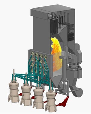
1. A typical MPS-89 pulverizer found in many coal-fired power plants. Courtesy: Storm Technologies Inc.
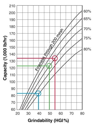
2. Typical expected performance for an MPS-89 pulverizer is based on the coal HGI and fineness. Source: Storm Technologies Inc.
Pulverizer Recovery
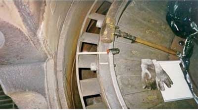
What is your first step after experiencing a burner fire, mill fire, mill puff, or a mill explosion? After the damage is repaired, how can the mill and burner system be safely and confidently returned to service? In our experience, the following steps have been found to be a safe and prudent course of action. Only after the mill is thoroughly checked out should it be released for operation (Figure 3).

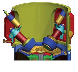
3. Typical locations within a mill that should be inspected after a fire or other operating anomaly. These are the locations of what we consider to be the most critical measurements and tolerances in the MPS pulverizer designs. On the left is a typical Alstom Power mill, on the right an MPS-89 of similar capacity. These two mill types represent perhaps 70% of the pulverizers used in modern pulverized coal plants. Courtesy: Storm Technologies Inc.
After a pulverizer incident, perform these steps prior to putting the mill back in service:
- Measure and record internal clearances, tolerances, and spring preloads.
- Check and calibrate the coal feeders.
- Functionally check the full movement and position indication of all dampers.
- Review primary airflow curves to ensure safe operation throughout the operating range, ensuring adequate minimum airflow as well as proper air-to-fuel ratios when operating above minimum airflow.
- After thoroughly checking mechanical tolerances and clearances, close the mill and start primary airflows. Warm the mill to normal operating temperature of 150F mill outlet temperature (bituminous coal) and airflow at minimum (normal minimum primary air [PA] flow).
- Conduct a PA airflow measurement traverse by manual pitot tube to verify that the indicated PA is correct across the boiler operating range.
- Conduct "clean air" 24-point traverses of all of the fuel lines to measure and compare the balanced airflows through each pipe. All coal pipes (and flows to all of the burners from each respective pulverizer) should be balanced and within ±2% of the mean flow.
- Perform a seal air check.
- Begin the normal pulverizer start sequence.
- Once normal coal flow is applied to the mill, a full mill test should be conducted. This test should include isokinetic coal sampling and dirty airflow measurements through each fuel line to determine air/fuel balance and coal fineness. Primary airflow "Hot-K" calibrations of the primary airflow measuring element should also be conducted.
A Four-Step Plan
Blueprinting a pulverizer isn’t rocket science, but it does require close attention to the details. Here is our four-step plan to restore and improve performance of your pulverizer, regardless of its age.
Step 1. Ensure that the grinding elements are in good condition. Make sure that the grinding surface profiles are optimum. That means using the original design grinding profiles for your mill. The majority of coal pulverizers sized around 120,000 pph use three grinding elements, referred to as journals, rolls, or tires. For best results, all three grinding elements should be replaced in matched sets. The concentricity, physical dimensions, and contours must be exactly the same. This is especially important when maximum preload pressure is required to produce maximum capacity with improved coal fineness and/or with lower-than-original design HGI. We have seen mills assembled with unmatched sets of three grinding journals using maximum spring pressure. The result of such setups: The main shafts break because of the unbalanced load. Matched sets of grinding elements and exactly the same size rolls with exactly the same contour are important for maximum reliability.
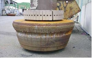
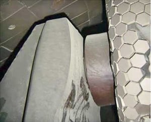
The grinding surfaces also must be in good condition and parallel (Figure 4). Don’t expect optimum performance if the grinding elements are well-worn or the tires are "flat" (Figure 5). Unusual wear patterns are often the result of uneven spring frame tolerances, alignment issues, pressure variations, geometry, and/or eccentricity issues.
4. Walk the line. The profile of the roll should be parallel with the grinding ring profile. Courtesy: Storm Technologies Inc.


5. In an MPS mill, the tire and table profiles must match, and the tires should not have flat spots. Courtesy: Storm Technologies Inc.
Step 2. Set the correct grinding pressure. Check your mill to confirm that the grinding roll or spring frame preload pressure is set correctly. Our experience with both RP and MPS pulverizers has been that mills designed for a throughput of about 120,000 pounds of coal per hour, an HGI of about 45 to 50, and coal fineness exceeding 75% passing 200 mesh will require about the same force on the grinding elements. It is reasonable to expect that grinding coal will take about the same amount of grinding element pressure regardless of the type of medium-speed, vertical-spindle pulverizers you use.
In our experience, the spring frame of an MPS mill tuned for maximum true capacity will be set at about 20 tons minimum force on the grinding tires. A bowl mill spring or hydraulic preload for this size of mill will also be about 20 tons of pressure. Lower-HGI fuel and fineness of greater than 75% passing of 200 mesh requires the maximum pressure of the grinding elements. Keep in mind that in operation there is no metal-to-metal contact, and all coal grinding results from the pressure applied coal particle-to-coal particle on a bed of coal squeezed between the grinding elements.
Internal clearances are also very important. For example, a bowl mill spring canister can be set to the needed preload, but if it is not adjusted for the "button" to roll with assembly minimum clearance, then the preloading does not come into play until the roll rides up on a deeper bed of coal (Figure 6). Ensuring sufficient grinding pressure is absolutely essential, and it begins with setting this critical tolerance.
For a spring frame mill, the hydraulic preload must be balanced across the mill and the grinding elements perfectly centered in the assembly (Figure 7).
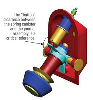
6. The "button" clearance between the spring canister and the journal assembly is a critical tolerance. Courtesy: Storm Technologies Inc.
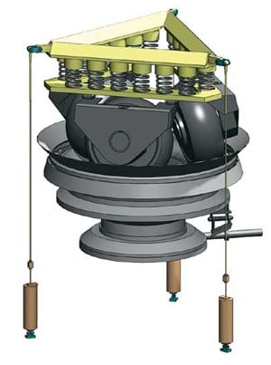
7. The MPS spring frame hydraulic preload must be carefully balanced and the spring frame centered for optimum mill performance. Courtesy: Storm Technologies Inc.
Step 3. Set the correct pulverizer throat clearance. An oversized pulverizer throat will require more than optimum primary airflow to minimize coal rejects. The pulverizer "free annular jet" of vertically flowing airflow, in our experience, must be adjusted for a minimum of 7,000 fpm under normal operation. Throats that are oversized will result in either excessive coal rejects (not tramp metal or pyrites, but raw coal).
Compounding the problem, high primary airflow is the main cause, in our experience, for poor fuel fineness, poor fuel distribution, and reduced furnace performance. Right-sizing the flow area of the pulverizer throats and matching them for compatibility with the coal pipes and burner nozzle sizes is essential for the best furnace performance. Furthermore, remember that there will be minor variation in mill capacity, fuel quality, and mill inlet airflow rates that must be considered when sizing the pulverizer throat flow area.
The vertically flowing air must be of sufficient velocity to suspend the granular coal bed in the grinding zone. Some designs use mechanical means to keep the coal above the under-bowl pyrite section, while others use airflow. Reducing coal rejects by mechanical means entails increasing the height of the "bull ring" extension ring or the extension of flat surfaces above the rotating throat to trap or dam coal particles mechanically so that they remain above the throat.
We prefer the optimum throat area fluidic solution to suspend the coal bed and reduce the potential for fires beneath the bowl or grinding table. Keep in mind that if the fuel is above 17% moisture and the air/fuel ratio is about 1.8, then the under-bowl primary air temperature will be above 450F. Any coal that falls through the throat opening will combust unless it is removed, in mere minutes. Combustion of coal particles beneath the grinding zone is not a serious problem, as long as the mill is in operation. But if a mill trips or a boiler has a main fuel trip, then fires in the pyrites zone (beneath the grinding zone) are the most common cause of pulverizer "puffs," in our experience. A fire beneath the grinding zone provides the ignition temperature to initiate a mill "puff" when restarting a mill after a trip or restarting it after a main fuel trip when coal remains in the bed.
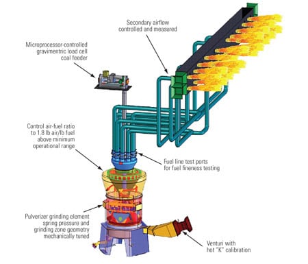
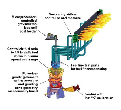
For safety as well as for performance reasons, properly sizing the mill throats is extremely important (Figure 8). The optimum throat area is determined by calculating the free annular jet area when the desired air/fuel ratio (usually 1.8 lb air/lb fuel) is known. The throat area also must be properly designed to be compatible with the flow areas of the burner coal pipes and coal nozzles (Figure 9). Only with the best possible pulverizer performance, proper fuel distribution, and optimum air/fuel ratio is optimum furnace performance possible.
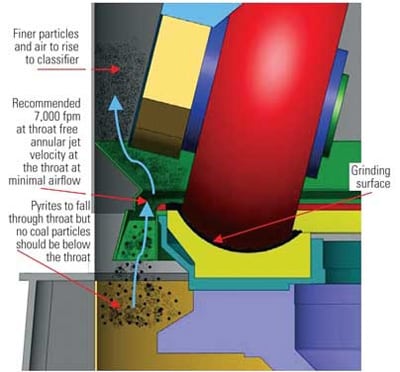
8. Ensure optimum arrangement of the mill throat and the coal flow path to improve mill performance. Courtesy: Storm Technologies Inc.
9. Pulverized coal mills with throats that are too wide will have corresponding low throat velocity in the mill grinding zone that contributes to excessive coal rejects and fires. This is an example of an oversized mill throat. Courtesy: Storm Technologies Inc.
Step 4. Properly maintain the classifier. Once the grinding zone is blueprinted and put in first-class condition, the next component to examine is the classifier. The best furnace combustion performance is governed by uniform coal combustion by the burners and satisfactory coal fineness. Adequate fineness for both western and eastern fuels (Powder River Basin or bituminous) is a minimum of 75% to 80% passing 200 mesh and zero to 0.1% remaining on a 50 mesh screen (Figure 10). To achieve this fineness, the pressurized mill classifier must perform two functions:
- It separates particles small enough to be supplied to the burners (mean particle size about 40 to 55 microns) from larger coal particles that need return to the grinding zone for regrinding.
- It contributes to the fuel balance to each coal pipe. This is important for the best furnace performance.

10. A classifier recirculates coarse coal in the grinding zone and balances the flow of coal to each burner line to the furnace. Couresty: Storm Technologies Inc.
The flow of coal particles through a classifier is several times the amount of coal flowing to the burners because of the large amount of coal recirculated within a pulverizer. For example, if a pulverizer is operating at 100,000 lb/hr coal feed to the burners, as much as 300,000 lb/hr or more may be flowing through the classifier for regrinding. For this reason the surface smoothness and inverted cone clearances or discharge doors of the MPS original design mills are extremely important for acceptable pulverizer performance and of course, optimum furnace performance.
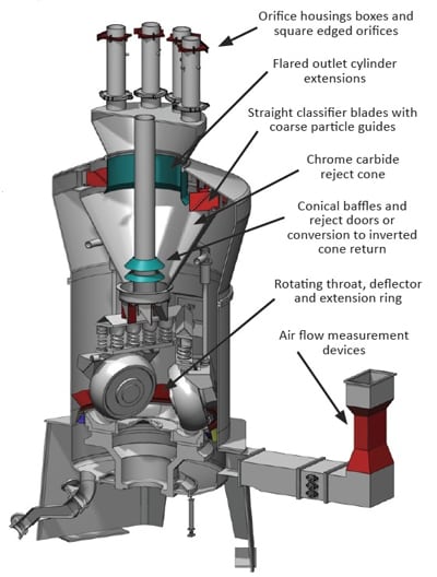
Our experience over the years has helped us develop a number of proven minor enhancements for achieving best classifier performance. The critical dimensions indicated in Figure 11 include:
- Surface smoothness of the classifier cone.
- Synchronized classifier blade angles and lengths.
- Inverted cone to classifier clearances.
- Classifier outlet cylinder length and flared opening.
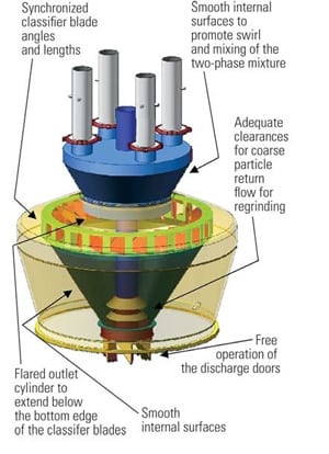
11. Areas of the classifier where performance can be improved. Courtesy: Storm Technologies Inc.
Other improvements that should be considered when overhauling a classifier include these:
- Smooth surfaces in the upper turret section for good fuel spinning and uniform distribution (no surface discontinuities, such as "pad eyes").
- Ensure the free movement and closure of the discharge doors (trickle valves).
- Confirm the sound and good condition of the classifier cone assembly (no holes should be worn through).
- Ensure the good mechanical condition of the classifier blades.
More to Come
In Part II we’ll examine how to measure pulverizer performance. In Part III, we’ll look at why precise measurement and control of primary air is important.
—Richard F. (Dick) Storm, PE is senior consultant for Storm Technologies Inc.