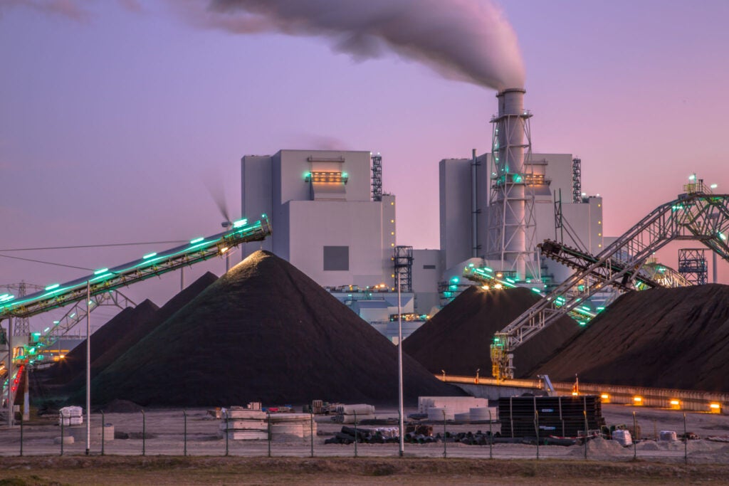
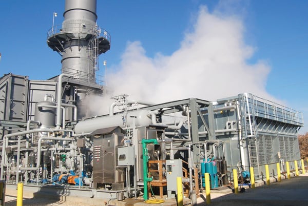
MeeFog’s very first installation of inlet air fogging was done at Harbor Cogen in Southern California in 1991 on a GE 7EA turbine where it continues to be used for power augmentation to this day (Figure 1). When it was installed, the fogging arrays were placed upstream of the air filters.

Since that time, more than 1,000 fogging projects have been carried out by Mee Industries at sites throughout North America and worldwide. The vast majority have fog nozzles installed downstream of the air filters. Some plants also install fog right before the compressor bell mouth for what is known as wet compression, which consists of spraying fog into the compressor where it evaporates and gives an intercooling effect.
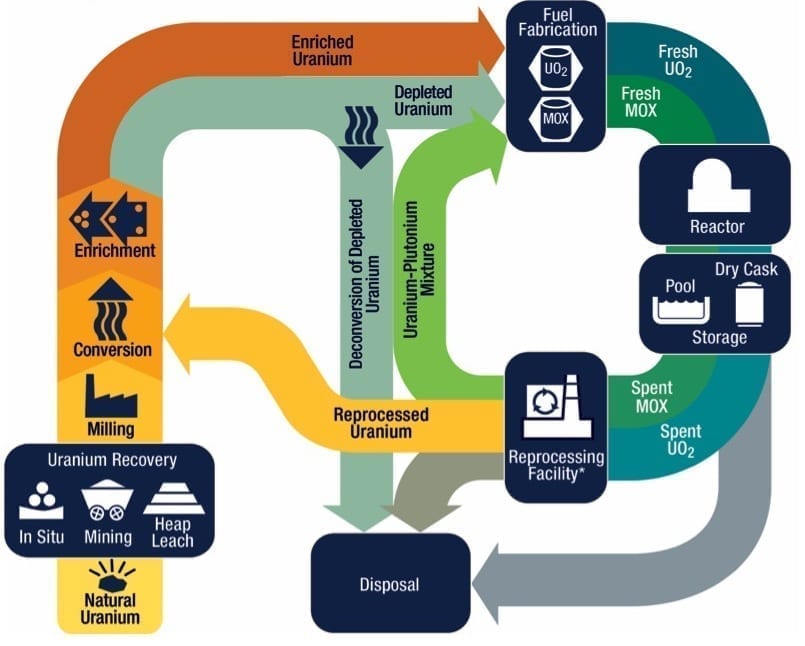
But more recently, there has been a revival in interest in placing the fogging arrays upstream of the air filters. Let’s compare these various configurations (Figure 2), explain why the upstream configuration is gaining more advocates, and provide examples of plants implementing this configuration.

Fogging Configurations
A combustion turbine’s output is dependent on the mass of the air being moved through its compressor. Lowering the air temperature increases the density of the air, which increases the mass flow and the power output. Cooler air also requires less work to compress, thereby lowering the parasitic load of the compressor and improving fuel efficiency.

In This Issue
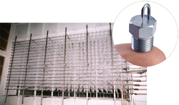
Full issueFog-based inlet air cooling cools the inlet air courtesy of a fog spray evaporating airflow before it flows to the gas turbine compressor. The fogging process involves demineralized water pressurized to 2,000 psi (138 bar) via a pump skid. The water is fed to MeeFog nozzles, which inject pure water fog into the inlet airflow. There are three basic positions for fogging arrays.
A. Downstream of the Air Filters. The fog spray evaporates in the inlet duct and cools the air as it flows to the gas turbine compressor inlet. This might be regarded as the standard configuration.
“About 90% of our installations have nozzles located downstream of the filters,” said Thomas Mee III, CEO of Mee Industries. “The advantages are that few changes need to be made to the filter house. About 98% of the water evaporates in the duct, the rest is drained away. By slightly over-spraying, humidity at the compressor inlet can approach 100%.”
Some drains need to be installed on the duct floor. The drain on the inlet plenum floor near the bell mouth should be converted to always be open by adding a one-way valve and/or a p-trap. Further, as the fogging array is positioned inside the inlet air duct, the turbine will have to be offline for a couple of days while the work is done. Nozzle arrays can be installed in a small turbine in less than 24 hours. For a large turbine, the installation typically takes three days, but it can also be done in 24 hours, if needed.
B. Wet Compression. In this configuration, the nozzle lines are placed just upstream of the compressor to enable the fog spray to enter the compressor. Wet compression is generally deployed along with regular inlet air fogging to avoid having large temperature differences at the compressor inlet. Unlike evaporative cooling, the power boost from wet compression does not depend on ambient conditions.
“Wet compression can add MW regardless of ambient conditions, so long as it is warm enough to avoid ice formation at the inlet (usually over 50F),” said Mee. “It adds only a few percent to the inlet air mass flow. Most of the power boost comes from intercooling, which reduces the power consumed by the compressor, so more work is available at the output shaft.”
Like configuration A above, wet compression requires taking the turbine offline to install the fogging arrays within the duct. It also requires a p-trap and one-way valve to ensure the drain on the inlet plenum floor is always open.
“Wet compression has been in greater demand in the last few years,” said Mee. “Operators of older turbines find wet compression helps them meet increased peaking power output in support of renewables.”
C. Upstream of the Air Filters. Placing fogging upstream of the inlet air filters requires the installation of droplet eliminators if they don’t already exist. When MeeFog was installed on two Siemens Energy SGT5-8000H turbines in Thailand, the existing droplet eliminators were sufficient to remove the fog droplets. This fogging configuration has also been installed on numerous LM6000 turbines, which are designed with coalescer filters upstream of the air filters. In a few other cases, though, MeeFog droplet eliminators have been installed upstream of the filters. Mee noted that fogging systems with droplet eliminators have been used for decades in heating, ventilation, and air conditioning (HVAC) air handlers to manage building humidification.
To approach 100% humidity in this configuration, it is necessary to spray more water than is required to fully cool and humidify the air. Unevaporated fog droplets are captured on a droplet filter and drained away. The amount of excess flow depends on the length of time the fog droplets are in the airflow, which in turn depends on the distance from the fog nozzles to the droplet eliminator and the velocity of the airflow. Droplet eliminators usually add little to overall costs. Upstream fogging offers a significant power boost despite being a little more expensive than configuration A, and it works well even in very humid environments, including in Bangkok.
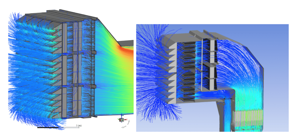
“It takes more than two seconds to fully evaporate even the very small MeeFog droplets. If less time is available, it is still possible to reach 100% humidity by spraying more water,” said Mee. “If only one second of evaporation time is available, spraying 15% more water will ensure that the air is cooled close to 100% relative humidity [Figure 3].”

One advantage of configuration C is that the fog spray captures dust in the air stream, which is carried away with the drain water. This improves air filter life. Drained water can be filtered, pumped back to the plant’s raw water tank and reused.
Another advantage is that downstream fogging and wet compression fogging both require demineralized water; whereas, upstream fogging can be done with untreated water. However, that water should be soft enough not to cause buildup of calcium carbonate on the fog nozzles and droplet eliminators, and should be treated with a biocide to prevent biological growth that could plug the fog nozzles.
“Softened city water would be sufficient quality for most installations, and upstream fogging can be used on any type of turbine,” said Mee.
For filter house designs that have existing droplet eliminators, it is sometimes possible to install fog nozzle lines at the inlet to the weather hoods without any other modification to the filter house. GE LM6000s, for example, often have coalescing prefilters, which make good droplet eliminators and many F- and H-class turbines have existing droplet eliminators that are sufficient for fogging.
Upstream Old, Upstream New
Depending on the turbine, its age, and any relevant contractual obligations, there can sometimes be restrictions due to warranties or long-term service agreements (LTSAs). As a result, some sites have recently requested their fogging nozzles be positioned immediately ahead of the inlet air filters to navigate original equipment manufacturer (OEM) objections.
Recent MeeFog upstream fogging installations on two 453-MW SGT5-8000H turbines in Bangkok, Thailand, produced 13 MW of additional power per gas turbine. The company will also install upstream fogging systems on several GE machines in the Middle East this year.
The fog systems for the SGT5-8000H machines were designed to provide only 9F (5C) of cooling but it would be possible to do as much as 15F (8C) on a hot and humid tropical day in Bangkok. In a more temperate climate, an upstream fog system could cool 30F (16C) and even more cooling is possible at locations with a hot and dry climate, said Mee.
Further, there are many upstream installations from the 1990s. In addition to Harbor Cogen, five 7EAs in Channel, Texas, had fogging installed upstream, as well as a GE 7F in Gilroy, California, and another 7EA in the Midwest.
“Fogging downstream of the filters became popular in the mid-nineties once it was demonstrated conclusively that fog droplets did not cause compressor blade erosion,” said Mee. “But upstream fogging is becoming popular again as some OEMs have recently disallowed downstream fogging and even wet compression systems on turbines covered by LTSAs.”
Upstream Fogging Case Study
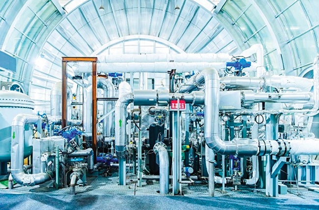
In 1996, Mee Industries installed a fogging system upstream of air filters on an LM6000 at Las Vegas Cogen (Figure 4), which remains in use to this day as part of the expanded Las Vegas Generation Station facility. “If time is limited to install a fogging system, place it outside of the filter house since you can install the headers at any time,” said Dan Unten, plant operator at Las Vegas Generating Station.

Las Vegas Cogen is a GE LM6000-based peaking plant operating in a climate with extended hot and dry summers. As a result, this facility initially employed a chiller system to maximize output. However, plant operators found that they couldn’t cool the inlet air to dewpoint during periods of high ambient temperature. That led management to order a MeeFog system to provide additional cooling.
It was positioned upstream of the inlet air filters and chiller coil to act as a pre-cooler. Normally this configuration would not work well because the evaporative cooling would be countered by the latent heat of condensation when the evaporated water was condensed onto the cooling coil. But for an undersized chiller in the hot and dry Nevada desert, evaporative precooling worked well.
“The misting banks were placed outside of the filter house to eliminate the downtime required to install the system,” said Unten. “We installed the system since we could not maintain our contracted output of 45 MW during hot summer days. With the fogging system installed, we could maintain our required plant output of 45 MWs.”
As it took time for the chillers to come online, high-pressure inlet fogging was used to quickly achieve maximum power. Fog alone is used when it’s below 70F outside. Above that, the steam absorption chiller was brought online with both running together. The fog system consists of 240 nozzles installed in three stages. The first cooling stage achieves 7F of cooling, two stages deliver 12F, and all three provide 15F. The overall result of fogging is an additional 5 MW of power output. Operating pressure is 2,000 psi.
The pressure drop associated with the fog nozzle manifold is nominal, added Unten. The existing heating coil and pad-type prefilters are used as fog droplet filters to remove any unevaporated fog. Although this prevented wetting of the primary air filters, water collects on the cooling coil and prefilter, and is drained off, slightly reducing the amount of cooling accomplished by the fog system. “Even though our fog system is upstream of the filters, the final barrier filters remain dry, and the filters stay cleaner due to the scrubbing effects of the fog,” Unten said.
For nearly three decades, this system has continued to operate. Pump, belt, motor, nozzles, and nozzle filter replacements have been needed as would be expected as part of routine maintenance.
“MeeFog has built a quality product, which has required minimal maintenance and has performed well above expectations,” said Unten. He reports that the original absorption chillers ceased to function about a year ago. Since then, fogging has been used as the only source of cooling.
“Since that time, they have lost minimal output from the plant even with no inlet chilling,” said Unten. “Running the fogging system during cooler days allows us to not use extraction steam, thus increasing the steam turbine output.”
—Drew Robb (drewrobb@sbcglobal.net) has been a full-time freelance writer for more than 25 years specializing in engineering and technology.